EP2196048B1 - Endgeräte-trace-aktivierung in einem drahtlosen kommunikationsnetz - Google Patents
Endgeräte-trace-aktivierung in einem drahtlosen kommunikationsnetz Download PDFInfo
- Publication number
- EP2196048B1 EP2196048B1 EP07852279.4A EP07852279A EP2196048B1 EP 2196048 B1 EP2196048 B1 EP 2196048B1 EP 07852279 A EP07852279 A EP 07852279A EP 2196048 B1 EP2196048 B1 EP 2196048B1
- Authority
- EP
- European Patent Office
- Prior art keywords
- terminal
- enode
- node
- trace
- traced
- Prior art date
- Legal status (The legal status is an assumption and is not a legal conclusion. Google has not performed a legal analysis and makes no representation as to the accuracy of the status listed.)
- Active
Links
Images


Classifications
-
- H—ELECTRICITY
- H04—ELECTRIC COMMUNICATION TECHNIQUE
- H04L—TRANSMISSION OF DIGITAL INFORMATION, e.g. TELEGRAPHIC COMMUNICATION
- H04L43/00—Arrangements for monitoring or testing data switching networks
-
- H—ELECTRICITY
- H04—ELECTRIC COMMUNICATION TECHNIQUE
- H04L—TRANSMISSION OF DIGITAL INFORMATION, e.g. TELEGRAPHIC COMMUNICATION
- H04L41/00—Arrangements for maintenance, administration or management of data switching networks, e.g. of packet switching networks
- H04L41/34—Signalling channels for network management communication
- H04L41/344—Out-of-band transfers
-
- H—ELECTRICITY
- H04—ELECTRIC COMMUNICATION TECHNIQUE
- H04W—WIRELESS COMMUNICATION NETWORKS
- H04W12/00—Security arrangements; Authentication; Protecting privacy or anonymity
- H04W12/02—Protecting privacy or anonymity, e.g. protecting personally identifiable information [PII]
Definitions
- the present invention relates to methods and arrangements in a mobile telecommunications network, and in particular to a signaling based activation of terminal trace via an evolved Node B (eNode B) from a Radio access network domain manager (RAN DM) in a radio access network comprising a plurality of eNode Bs connected directly to the core network (CN).
- eNode B evolved Node B
- RAN DM Radio access network domain manager
- UTRAN Universal terrestrial radio access network
- UMTS Universal Mobile Telecommunication System
- the UTRAN consists of Radio Network Controllers (RNCs) and Node Bs (i.e. radio base stations).
- RNCs Radio Network Controllers
- Node Bs communicates wirelessly with mobile terminals and the RNCs control the Node Bs.
- the RNCs are further connected to the Core Network (CN).
- Evolved UTRAN eUTRAN
- eUTRAN is an evolution of the UTRAN towards a high-data rate, low-latency and packet-optimised radio access network.
- eUTRAN does only consist of eNode Bs (evolved Node Bs), and the eNode Bs are interconnected and further connected to the CN.
- eUTRAN is also being referred to as Long Term Evolution (LTE).
- operation and maintenance functionality of the radio access network requires information regarding a specific terminal. Hence it may be desired to trace a sequence of events of this specific terminal in relation to the access network. In order to be able to receive this information, the operation and maintenance functionality must be able to trace the terminal.
- the operation and maintenance functionality is aware of in which Radio Access Network (RAN) it is desired to activate traces upon entry of the terminal that is desired to trace. Further it is also known which radio network controllers (RNC) belong to this RAN. Thus, the operation and maintenance functionality sends a request for a trace to the relevant RNCs, and makes the RNCs responsible for the trace.
- the RNC is aware of IMSI (International Mobile Subscriber Identity) and can therefore take care of all trace requests where the terminal is identified by the IMSI.
- IMSI International Mobile Subscriber Identity
- the operation and maintenance functionality may use the IMEI(SV) (International Mobile Equipment Identity) to identify the terminals but the RNCs are not aware of the IMEI(SV).
- the IMEI identifies the mobile terminal and the IMEI(SV) also includes information on the origin, model, and serial number of the mobile terminal. Therefore, each RNC of the RAN has to communicate with the core network (CN) that is aware of the IMEI(SV) when the IMEI or IMEI(SV) is used for identifying the terminal.
- the RNCs When the RNCs have received information from the CN of the IMEI or the IMEI such that it can identify the terminal to be traced, the RNC activate the trace locally on the RNC.
- the trace mechanisms of prior art do not allow for spreading of the trace to any other nodes. The prior art trace mechanism is further described in the 3GPP TS 32.422. In TS 32.422 the term Element Manager (EM) is used for the entity which in this specification is denoted DM (Domain Manager).
- EM Element Manager
- LTE Long Term Evolution
- 3GPP TS 32.421/2/3 documents for Release 8 of the 3GPP specifications describe an interface between the RAN DM and the Core Network DM which is a P2P (peer-to-peer) connection which is in the initial stages of standardization.
- P2P peer-to-peer
- the RAN DM provides a package of operator functions for management of a set of closely related types of network elements.
- the RAN DM In LTE, there exists no RNC, and the operation and maintenance functionality, referred to as RAN DM, has no knowledge where in the network the terminal to be traced is located. It only knows in which CN it is desired to activate traces. As in the UTRAN, the RAN DM identifies the terminals by the IMSI and the eNodeB (i.e. an RBS in a LTE network) are not aware of the IMSI identity.
- the subscriber or terminal trace must be activated via signaling based activation from the CN. Further, the CN needs to be triggered to start the trace of a subscriber or terminal.
- the UTRAN prior art makes it necessary to contact every RNC within a RAN to enable the trace on that RAN. This is acceptable for UTRAN that may include up to 10 RNCs. However in LTE where there exist no RNCs there may be up to 5000 Node Bs. That would cause very heavy load on the system if it is required to contact each Node B every time a terminal trace needs to be initiated.
- the UTRAN prior art has a geographical area for the activation of a terminal trace. This geographical area is based on the RNCs which no longer exist in the LTE system.
- the solution according to the UTRAN prior art is designed for a radio network comprising RNCs, and not for a radio network with only eNodeBs. Also, the solution of the UTRAN prior art does not handle the case when there is no permanent identity for the UE. In UTRAN it is assumed that the IMSI is available in the RNC but in the eUTRAN the IMSI is not allowed to be available in the eNode B due to security reasons.
- the object of the present invention is to provide an efficient mechanism for activating a terminal trace in a mobile communications network, comprising a plurality of radio base stations (e.g. eNode Bs) directly connected to a core network, such as the eUTRAN.
- a radio base station e.g. eNode Bs
- core network such as the eUTRAN
- the basic idea of the present invention is to allow for the activation of a terminal trace which needs to be activated in the Core Network from a RAN DM through a first eNodeB that is selected independently of the location of the terminal to be traced.
- the first eNode B forwards the trace request to the CN and the CN stores information relating to the trace request in a global manner such that the trace request may be sent to any eNode B that is being controlled by said CN node. Since the CN stores the trace information in the global manner the trace may be activated on any eNode B that is connected to said CN, which implies that the trace request can be sent to any of the eNode Bs of the CN.
- a RAN DM comprises means for selecting a first eNode B independently of the location of the terminal to be traced and means for sending a request comprising the first terminal identity for the terminal to be traced to the first eNodeB.
- the terminal trace request is then forwarded to a CN node, which CN node is arranged to store information relating to the trace request in a global manner and to control the first eNode B and a second eNode B that is controlling the terminal to be traced.
- a CN node comprises means for receiving a terminal trace request for the terminal to be traced from a RAN DM via a first eNodeB that is selected independently of the location of the terminal to be traced. It further comprises a trace information storage configured to globally store terminal trace related information such that a trace can be activated on any eNode B that is connected to said CN node, means for receiving an identity of a second eNode B that is controlling the terminal to be traced, and means for sending the terminal trace request to the second eNodeB, such that the second eNode B can perform the terminal trace.
- methods comprising the steps of sending a request for the terminal to be traced from the RAN DM to a first eNodeB that is selected independently of the location of the terminal to be traced, forwarding the request from the first eNodeB to a CN node, receiving in the CN node a terminal trace request for the terminal to be traced from a RAN DM via a first eNodeB that is selected independently of the location of the terminal to be traced, storing terminal trace related information globally such that a trace can be activated on any eNode B that is connected to said CN node, receiving an identity of a second eNode B that is controlling the terminal to be traced, and sending the terminal trace request to the second eNodeB, such that the second eNode B can perform the terminal trace.
- An advantage with the present invention is that it allows for activation of a terminal trace on all eNode Bs which are connected to a single CN by signaling only one eNode B. This is in contrast to the prior art where signaling to every eNodeB would be required, which would cause much load in the network as there may be thousands of eNodeBs connected to one CN node.
- a further advantage with the present invention is that it allows for the terminal trace to be easily activated by a single signal on a very large geographical area.
- the RNC usually controls around 500 Node Bs.
- the area covered by 500 Node Bs is a limited area to initiate a terminal trace in a city or commuter belt around a city where people travel large distances in a short time and with Node Bs that are located closely together.
- the present invention allows the activation of the trace on a very large area which is covered by a full CN node.
- a full CN node may cover an entire city in itself and may contain several thousand eNode Bs.
- a further advantage with the present invention is that the trace files are stored and managed in one DM. This gives the operator a very easy and intuitive way to use the terminal trace.
- a further advantage is that the eUTRAN activation of the terminal trace is made possible without the use of P2P (Peer-to-peer) connection between the Core Network DM and the RAN DM.
- P2P Peer-to-peer
- a yet further advantage is that the present invention allows for easy invocation of a terminal trace from a RAN in a multi-vendor environment.
- the present invention relates to mechanisms for activation of a terminal trace in a radio access network comprising radio base stations 100 directly connected to a CN 110 which is illustrated in figure 1 .
- the terminal 120 to be traced communicates wirelessly with one or more of the radio base stations 100.
- the radio access network may be an LTE (i.e. eUTRAN) based radio access network.
- the terminal trace is activated by means of a RAN DM 130 which is an interface for operators towards the radio access network nodes of the LTE network. I.e. the operators use the RAN DM to manage the network including asking for a specific terminal to be traced.
- the RAN DM may also be referred to as an eUTRAN DM.
- the basic idea of the present invention is to allow for activation of a terminal trace which needs to be activated in the CN from a RAN DM through a first eNodeB that is selected independently of the location of the terminal to be traced. This selection may be performed during a pre-configuration.
- the operator initiates a terminal trace via the RAN DM and the RAN DM signals a terminal trace request message to the first eNodeB to initiate the terminal trace with the subscriber's (i.e. the subscriber of the terminal to be traced) permanent identity (e.g. the IMSI).
- This permanent identity is also referred to as a first terminal identity.
- the first eNodeB is configured to act as a router and transparently forwards the terminal trace request message to a CN node, e.g. the Mobility Management Entity (MME) via a control plane signaling (e.g. via the S1 interface).
- MME Mobility Management Entity
- the CN node comprises means for receiving the terminal trace request and for storing the trace information associated with the trace request.
- the trace information is stored globally in the CN node which implies that the trace request can be activated on any eNode B that is connected to the CN.
- the CN node can identify the eNode B that is controlling the terminal to be traced referred to as the second eNode B. Since the trace information is stored globally within the CN node, this trace information can be used for any eNode B connected to the CN node according to the present invention. I.e. when the CN node has received a call setup message from the UE such as an initial UE context message it responds to the UE via the second eNode B and piggybacking the response message with trace information comprising a second terminal identity that can be used by the eNode B.
- the second terminal identity e.g.
- the CN node comprises trace information storage, means for identifying the eNode B that is controlling the terminal to be traced and means for sending the trace request to the identified second eNode B. It should be noted that the CN node can send the trace request to any eNode B that is being controlled by the CN node thanks to the global storage of the trace information in the CN node.
- FIG 2 showing a flowchart of a method according to an embodiment of the present invention.
- Step 200 Operator inputs trace configuration parameters i.e. UE/subscriber identity, level of tracing to be configured etc. It may be an option for the operator to manually enter the second identity if not the RAN DM creates second identity. This second identity may hence be included in the trace configuration parameters which are sent to the first eNode B.
- trace configuration parameters i.e. UE/subscriber identity, level of tracing to be configured etc. It may be an option for the operator to manually enter the second identity if not the RAN DM creates second identity. This second identity may hence be included in the trace configuration parameters which are sent to the first eNode B.
- the RAN DM selects a first eNodeB that is connected to the Core Network(CN) node(s) that the terminal trace should be initiated on.
- One or more MMEs may be selected to turn on a UE/Subscriber trace, which implies that a plurality of first eNode Bs may be selected if the plurality of first eNode Bs belong to different CNs).
- the selected first eNodeB has to be connected to the same CN(s) as the terminal to be traced but the selection is made independently of the location of said terminal. (It should be noted that the first eNode B may be connected to more than one CNs.)
- the RAN DM may perform this selection in many ways. E.g. by manually entering one or more eNodeBs per CN node or by dynamically scanning all eNodeBs and select one at random for each CN node or one eNode B for several MMEs etc.
- Step 202 The RAN DM sends a request for terminal trace to the selected first eNodeB with the trace information necessary for the activation of the signaling based terminal trace in the Core Network, comprising the first terminal identity or the first and the second identity.
- Step 203 The first eNodeB receives the request for the terminal tracing from the RAN DM.
- the protocol over which this message is sent is not relevant to this invention but it may be a standardized 3GPP protocol or a proprietary protocol. Which ever protocol is selected will have a termination point which will receive the message and decode the information. This termination point will decode the message and forward it to a part of the first eNodeB which can build an S1 message.
- Step 204 The first eNodeB will then build the S1 message which will convey the trace information, i.e. the first terminal identity or the first and second identity (and other parameters), that it has received from the RAN DM.
- This message may be a message similar to the RANAP "Uplink Information Exchange Request" message or any similar message which can carry the information on the interface to the CN nodes to which it is connected. It should be noted that trace information is also being referred to as trace configuration parameters.
- Step 205 The first eNodeB will then send the message similar to the RANAP "Uplink Information Exchange Request" message to all attached CN nodes over an interface (S1 in the case of LTE). This message will contain the trace information which was received from the RAN DM as described above.
- Step 206 The CN node receives the message containing the trace information.
- the trace information comprises either the first terminal identity or the first terminal identity and the second identity. If the trace information only comprises the first terminal identity, the second identity is created in the CN.
- the CN node may respond with an acknowledgement for reception of the request. (Not shown.)
- Step 207 The CN node then stores the trace information globally in a trace information storage, which implies that a terminal trace may be activated on any eNode B connected to said CN node. I.e. a terminal trace may be performed for a terminal independently on which eNode B that it is covered by. This may be done by storing the trace parameters in the User Equipment (UE) context register within the CN node.
- UE User Equipment
- the CN node is preferably a MME and the terminal trace can hence be activated on the entire MME.
- Step 208 The terminal to be traced performs a call setup via the eNodeB which currently is controlling said terminal.
- This eNode B is referred to as a second eNode B.
- Step 209 The CN node receives the initial UE context message. From this message the CN node identifies the second eNode B that is controlling the terminal to be traced.
- Step 210 The CN node checks the trace information storage area to see if the terminal has a trace initiated. When it finds the answer to be yes, the trace is activated by sending the second identity and other trace configuration data from the CN node to the second eNodeB by piggy backing the trace configuration data on an initial message which is sent to the terminal during the call setup e.g. on SAE BEARER SETUP or INITIAL UE CONTEXT REQUEST. (I.e. the trace is now like a normal Signaling Based Activation UE or Subscriber Trace).
- the second eNode B receives the trace configuration data and starts the subscriber or equipment trace as per the prior art.
- the eNode B may spread the trace configuration data to other eNode Bs if the terminal is mobile and is handed over to another eNode B.
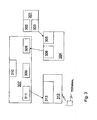
- the RAN DM 301 comprises means for selecting 302 a first eNode B independently of the location of the terminal to be traced and means for sending 303 a request, comprising at least the first terminal identity for the terminal to be traced, to the first eNodeB.
- the first eNode B 304 comprises means for receiving 305 the terminal trace request and means for forwarding 306 said request.
- the CN node 307 comprises means for receiving 308 a request for the terminal to be traced from the RAN DM via the first eNodeB that is selected independently of the location of the terminal to be traced. It further comprises means for receiving 309 an identity of a second eNode B that is controlling the terminal to be traced and a trace information storage 310 configured to globally store trace information such that a trace may be activated on any eNode B connected to the CN.
- the CN node comprises means for sending 311 the terminal trace request comprising a second terminal identity to the second eNodeB, such that the second eNode B can perform the terminal trace, wherein the second eNode B may be any eNode B that is controlled by the CN node.
- the first terminal identity is unknown by the eNode Bs whereas the second terminal identity can be used by the eNodeBs.
- the second identity of the terminal to be traced may either be obtained from the RAN DM or created in the CN.
- the second eNode B 312 that is controlling the terminal to be traced comprises means for receiving 313 the terminal trace.
- the present invention is applicable to all radio base stations having a similar functionality as the eNode Bs in the eUTRAN.
- the present invention is not limited to eUTRAN but can be used in any radio access network having a similar architecture as the eUTRAN.
Landscapes
- Engineering & Computer Science (AREA)
- Computer Networks & Wireless Communication (AREA)
- Signal Processing (AREA)
- Mobile Radio Communication Systems (AREA)
Claims (20)
- Funkzugangsnetz-Domänenmanager (130), RAN DM, für ein Mobil-Telekommunikationsnetzwerk, das eine Vielzahl von mit CN-Knoten (110) verbundenen eNodeBs (100) umfasst, die dafür konfiguriert sind, eine Endgeräteverfolgung eines zu verfolgenden Endgeräts zu aktivieren, worin eine den eNodeBs nicht bekannte erste Endgeräteidentität verwendet wird, um das zu verfolgende Endgerät zu identifizieren, dadurch gekennzeichnet, dass der RAN DM umfasst: ein Mittel zum Auswählen (201) eines ersten eNodeB (100), unabhängig vom Standort des zu verfolgenden Endgeräts (120), und ein Mittel zum Senden (202) einer Endgeräteverfolgungsanfrage, welche die erste Endgeräteidentität für das zu verfolgende Endgerät umfasst, an den ersten eNodeB, zur Weiterleitung der Endgeräteverfolgungsanfrage zu einem CN-Knoten, wobei dieser CN-Knoten dafür eingerichtet ist, Information bezüglich der Verfolgungsanfrage auf eine globale Weise zu speichern und den ersten eNodeB und einen zweiten eNodeB, der dafür eingerichtet ist, das zu verfolgende Endgerät zu steuern, zu steuern.
- RAN DM nach Anspruch 1, worin die Anfrage eine zweite Endgeräteidentität umfasst, die durch die eNodeBs verwendet werden kann, um in einer Nachricht vom CN-Knoten an den zweiten eNodeB huckepack transportiert zu werden.
- RAN DM nach einem der vorigen Ansprüche 1 bis 2, worin die erste Endgeräteidentität eine IMSI ist.
- RAN DM nach einem der vorigen Ansprüche 2 bis 3, worin die zweite Endgeräteidentität eine Verfolgungsreferenz ist.
- RAN DM nach einem der vorigen Ansprüche 1 bis 4, worin er ein Mittel zum Vorkonfigurieren der Auswahl des ersten eNodeB umfasst.
- RAN DM nach einem der vorigen Ansprüche 1 bis 4, worin er ein Mittel zum dynamischen Scannen von eNodeBs und Auswählen des ersten eNodeB für den CN-Knoten umfasst.
- Kernnetzwerk-(CN-)Knoten (110), umfassend eine Schnittstelle zur Verbindung mit einer Vielzahl von eNodeBs in einem Mobil-Telekommunikationsnetzwerk, worin der CN-Knoten dafür konfiguriert ist, eine Endgeräteverfolgung eines zu verfolgenden Endgeräts (120) zu aktivieren, und worin das Endgerät (120) durch eine den eNodeBs nicht bekannte erste Endgeräteidentität identifiziert wird, dadurch gekennzeichnet, dass der CN-Knoten umfasst: ein Mittel zum Empfangen einer Endgeräteverfolgungsanfrage für das zu verfolgende Endgerät von einem Funkzugangsnetz-Domänenmanager, RAN DM, über einen ersten eNodeB, der unabhängig vom Standort des zu verfolgenden Endgeräts ausgewählt wird; einen Verfolgungsinformationsspeicher, der dafür konfiguriert ist, endgeräteverfolgungsbezogene Information global zu speichern, sodass eine Verfolgung auf jedem eNodeB aktiviert werden kann, der mit dem CN-Knoten verbunden ist; ein Mittel zum Empfangen einer Identität eines zweiten eNodeB, der das zu verfolgende Endgerät steuert; und ein Mittel zum Senden der Endgeräteverfolgungsanfrage an den zweiten eNodeB, sodass der zweite eNodeB die Endgeräteverfolgung durchführen kann.
- CN-Knoten nach Anspruch 7, worin der CN-Knoten eine Mobilitätsmanagementinstanz ist.
- CN-Knoten nach einem der Ansprüche 7 bis 8, worin die vom RAN DM über den ersten eNodeB empfangene Anfrage eine zweite Endgeräteidentität umfasst, die durch die eNodeBs verwendet werden kann, um in einer Nachricht vom CN-Knoten an den zweiten eNodeB huckepack transportiert zu werden.
- CN-Knoten nach Anspruch 9, worin er ein Mittel zum Erzeugen der zweiten Endgeräteidentität umfasst, die durch die eNodeBs verwendet werden kann, um in einer Nachricht vom CN-Knoten an den zweiten eNodeB huckepack transportiert zu werden.
- CN-Knoten nach einem der vorigen Ansprüche 7 bis 10, worin er ein Mittel zum Erlangen von Information über die Identität des zweiten eNodeB, wenn das zu verfolgende Endgerät einen Verbindungsaufbau durchführt, umfasst.
- Verfahren für einen Funkzugangsnetz-Domänenmanager (130), RAN DM, in einem Mobil-Telekommunikationsnetzwerk, das eine Vielzahl von mit CN-Knoten verbundenen eNodeBs (100) zum Aktivieren einer Endgeräteverfolgung eines zu verfolgenden Endgeräts umfasst, worin eine den eNodeBs nicht bekannte erste Endgeräteidentität verwendet wird, um das zu verfolgende Endgerät zu identifizieren, dadurch gekennzeichnet, dass das Verfahren die Schritte umfasst:- Auswählen (201) eines ersten eNodeB, unabhängig vom Standort des zu verfolgenden Endgeräts, und- Senden (202) einer Endgeräteverfolgungsanfrage, welche die erste Endgeräteidentität für das zu verfolgende Endgerät umfasst, an den ersten eNodeB, zur Weiterleitung der Endgeräteverfolgungsanfrage zu einem CN-Knoten, wobei dieser CN-Knoten Information bezüglich der Verfolgungsanfrage auf eine globale Weise speichert und den ersten eNodeB und einen zweiten eNodeB, der das zu verfolgende Endgerät steuert, steuert.
- Verfahren nach Anspruch 12, worin die Anfrage eine zweite Endgeräteidentität umfasst, die durch die eNodeBs verwendet werden kann, um in einer Nachricht vom CN-Knoten an den zweiten eNodeB huckepack transportiert zu werden.
- Verfahren nach einem der vorigen Ansprüche 12 bis 13, worin der Auswahlschritt den Schritt umfasst: Vorkonfigurieren der Auswahl des ersten eNodeB.
- Verfahren nach einem der vorigen Ansprüche 12 bis 14, worin der Auswahlschritt den Schritt umfasst: dynamisches Scannen von eNodeBs und Auswählen des ersten eNodeB für den CN-Knoten.
- Verfahren in einem Kernnetzwerk-(CN-)Knoten (110) eines Mobil-Telekommunikationsnetzwerks, das eine Vielzahl von mit dem CN-Knoten verbundenen eNodeBs (100) umfasst, die dafür konfiguriert sind, eine Endgeräteverfolgung eines zu verfolgenden Endgeräts (120) zu aktivieren, worin das Endgerät durch eine den eNodeBs nicht bekannte erste Endgeräteidentität identifiziert wird, dadurch gekennzeichnet, dass das Verfahren die Schritte umfasst:- Empfangen (206) einer Endgeräteverfolgungsanfrage für das zu verfolgende Endgerät von einem Funkzugangsnetz-Domänenmanager, RAN DM, über einen ersten eNodeB, der unabhängig vom Standort des zu verfolgenden Endgeräts ausgewählt wird,- globales Speichern (207) von endgeräteverfolgungsbezogener Information, sodass eine Verfolgung auf jedem eNodeB aktiviert werden kann, der mit dem CN-Knoten verbunden ist,- Empfangen (208/209) einer Identität eines zweiten eNodeB, der das zu verfolgende Endgerät steuert, und- Senden (210) der Endgeräteverfolgungsanfrage an den zweiten eNodeB, sodass der zweite eNodeB die Endgeräteverfolgung durchführen kann.
- Verfahren nach Anspruch 16, worin der CN-Knoten eine Mobilitätsmanagementinstanz ist.
- Verfahren nach einem der Ansprüche 16 bis 17, worin die vom RAN DM über den ersten eNodeB empfangene Anfrage eine zweite Endgeräteidentität umfasst, die durch die eNodeBs verwendet werden kann, um in einer Nachricht vom CN-Knoten an den zweiten eNodeB huckepack transportiert zu werden.
- Verfahren nach Anspruch 18, worin es den Schritt umfasst: Erzeugen der zweiten Endgeräteidentität, die durch die eNodeBs verwendet werden kann, um in einer Nachricht vom CN-Knoten an den zweiten eNodeB huckepack transportiert zu werden.
- Verfahren nach einem der vorigen Ansprüche 16 bis 19, worin die Identität des zweiten eNodeB empfangen wird, wenn das zu verfolgende Endgerät einen Verbindungsaufbau durchführt.
Applications Claiming Priority (2)
| Application Number | Priority Date | Filing Date | Title |
|---|---|---|---|
| US97779407P | 2007-10-05 | 2007-10-05 | |
| PCT/SE2007/051008 WO2009045138A1 (en) | 2007-10-05 | 2007-12-14 | Terminal trace activation in a wirless communications network |
Publications (3)
| Publication Number | Publication Date |
|---|---|
| EP2196048A1 EP2196048A1 (de) | 2010-06-16 |
| EP2196048A4 EP2196048A4 (de) | 2013-09-04 |
| EP2196048B1 true EP2196048B1 (de) | 2014-11-19 |
Family
ID=40526441
Family Applications (1)
| Application Number | Title | Priority Date | Filing Date |
|---|---|---|---|
| EP07852279.4A Active EP2196048B1 (de) | 2007-10-05 | 2007-12-14 | Endgeräte-trace-aktivierung in einem drahtlosen kommunikationsnetz |
Country Status (2)
| Country | Link |
|---|---|
| EP (1) | EP2196048B1 (de) |
| WO (1) | WO2009045138A1 (de) |
Families Citing this family (6)
| Publication number | Priority date | Publication date | Assignee | Title |
|---|---|---|---|---|
| CN102238506B (zh) * | 2010-05-07 | 2014-04-09 | 中兴通讯股份有限公司 | 信令跟踪方法、装置和系统 |
| CN102695181B (zh) * | 2011-03-24 | 2015-05-13 | 华为技术有限公司 | 一种信令跟踪方法、装置和系统 |
| CN102355679A (zh) * | 2011-09-08 | 2012-02-15 | 中兴通讯股份有限公司 | 一种实现网络中移动用户信息采集的方法、基站及系统 |
| WO2013159795A1 (en) * | 2012-04-27 | 2013-10-31 | Telefonaktiebolaget L M Ericsson (Publ) | Nodes and methods for monitoring of communication |
| CN106332128A (zh) * | 2015-06-30 | 2017-01-11 | 中兴通讯股份有限公司 | 一种用户数据跟踪的方法和装置 |
| EP3468239B1 (de) * | 2016-07-04 | 2020-02-05 | Huawei Technologies Co., Ltd. | Verfahren und vorrichtung zur verwaltung des imsi-zustands einer endgerätevorrichtung |
Family Cites Families (4)
| Publication number | Priority date | Publication date | Assignee | Title |
|---|---|---|---|---|
| FR2855006B1 (fr) * | 2003-05-12 | 2005-08-05 | Nortel Networks Ltd | Procede d'activation d'enregistrements d'evenements relatifs a des terminaux et equipements pour la mise en oeuvre du procede |
| US20070226701A1 (en) * | 2006-03-23 | 2007-09-27 | Nokia Corporation | Automated central trace management |
| WO2008105687A1 (en) * | 2007-02-27 | 2008-09-04 | Telefonaktiebolaget Lm Ericsson (Publ) | Ordering tracing of wireless terminal activities |
| US8190136B2 (en) * | 2007-02-27 | 2012-05-29 | Telefonaktiebolaget L M Ericsson (Publ) | Initiating tracing of wireless terminal activities |
-
2007
- 2007-12-14 EP EP07852279.4A patent/EP2196048B1/de active Active
- 2007-12-14 WO PCT/SE2007/051008 patent/WO2009045138A1/en not_active Ceased
Also Published As
| Publication number | Publication date |
|---|---|
| EP2196048A1 (de) | 2010-06-16 |
| EP2196048A4 (de) | 2013-09-04 |
| WO2009045138A1 (en) | 2009-04-09 |
Similar Documents
| Publication | Publication Date | Title |
|---|---|---|
| EP3637683B1 (de) | Sitzungsverwaltungsverfahren, funktionsgerät und system | |
| US20200205065A1 (en) | Network entity, user equipment and method for the control and use of network slices | |
| CN105554789B (zh) | 通信系统、方法和装置 | |
| JP5273406B2 (ja) | セキュリティアルゴリズムを選択するためのシステム及び方法 | |
| US20100267388A1 (en) | Auto configuration of mobility entity | |
| US20070280177A1 (en) | Managing user profile information in a mobile telecommunications network | |
| CN101272576B (zh) | 一种用户信令跟踪方法及通讯系统以及用户设备 | |
| US20130090123A1 (en) | Method and Device for a Relay Node | |
| US7383035B2 (en) | Method of furnishing illegal mobile equipment user information | |
| CN108605383A (zh) | 无线通信系统中执行用于基于网络切片的nr的小区规范过程的方法和装置 | |
| CA2410544A1 (en) | Method for supporting a handover between radio access networks | |
| EP2196048B1 (de) | Endgeräte-trace-aktivierung in einem drahtlosen kommunikationsnetz | |
| US10448286B2 (en) | Mobility in mobile communications network | |
| JP2023109930A (ja) | Amfデバイスにおいて実行される方法及びamfデバイス | |
| US20040258019A1 (en) | Forwarding a terminal identity between core network nodes | |
| US20160227597A1 (en) | Radio node communicating with terminal in communication environment supporting plurality of radio networks, and radio communication method | |
| US20180077744A1 (en) | Communication system | |
| EP3522668B1 (de) | Verfahren und vorrichtung zum herstellen einer vertrauensbeziehung | |
| US7136646B1 (en) | Method and apparatus for electing an identification confirmation information | |
| US10051513B2 (en) | Method and apparatus for obtaining authentication information | |
| CN104244247A (zh) | 非接入层、接入层安全算法处理方法及设备 | |
| US20180007534A1 (en) | Mobility management switching center, communication system, and communication control method | |
| EP3148256B1 (de) | Benutzerverwaltungsverfahren, entsprechende vorrichtung und system für gemeinsam genutztes netzwerk | |
| CN104521261B (zh) | 用于使得在电信网络中能够合法侦听的方法、用户装置和基站收发台 | |
| EP1128686A1 (de) | Sprach-fähige GPRS Stützknotenpunkte |
Legal Events
| Date | Code | Title | Description |
|---|---|---|---|
| PUAI | Public reference made under article 153(3) epc to a published international application that has entered the european phase |
Free format text: ORIGINAL CODE: 0009012 |
|
| 17P | Request for examination filed |
Effective date: 20100325 |
|
| AK | Designated contracting states |
Kind code of ref document: A1 Designated state(s): AT BE BG CH CY CZ DE DK EE ES FI FR GB GR HU IE IS IT LI LT LU LV MC MT NL PL PT RO SE SI SK TR |
|
| AX | Request for extension of the european patent |
Extension state: AL BA HR MK RS |
|
| DAX | Request for extension of the european patent (deleted) | ||
| A4 | Supplementary search report drawn up and despatched |
Effective date: 20130801 |
|
| RIC1 | Information provided on ipc code assigned before grant |
Ipc: H04W 24/00 20090101AFI20130726BHEP |
|
| GRAP | Despatch of communication of intention to grant a patent |
Free format text: ORIGINAL CODE: EPIDOSNIGR1 |
|
| INTG | Intention to grant announced |
Effective date: 20140620 |
|
| GRAS | Grant fee paid |
Free format text: ORIGINAL CODE: EPIDOSNIGR3 |
|
| GRAP | Despatch of communication of intention to grant a patent |
Free format text: ORIGINAL CODE: EPIDOSNIGR1 |
|
| GRAF | Information related to payment of grant fee modified |
Free format text: ORIGINAL CODE: EPIDOSCIGR3 |
|
| GRAA | (expected) grant |
Free format text: ORIGINAL CODE: 0009210 |
|
| INTG | Intention to grant announced |
Effective date: 20141009 |
|
| AK | Designated contracting states |
Kind code of ref document: B1 Designated state(s): AT BE BG CH CY CZ DE DK EE ES FI FR GB GR HU IE IS IT LI LT LU LV MC MT NL PL PT RO SE SI SK TR |
|
| REG | Reference to a national code |
Ref country code: GB Ref legal event code: FG4D |
|
| REG | Reference to a national code |
Ref country code: CH Ref legal event code: EP |
|
| REG | Reference to a national code |
Ref country code: AT Ref legal event code: REF Ref document number: 697610 Country of ref document: AT Kind code of ref document: T Effective date: 20141215 |
|
| REG | Reference to a national code |
Ref country code: IE Ref legal event code: FG4D |
|
| REG | Reference to a national code |
Ref country code: DE Ref legal event code: R096 Ref document number: 602007039379 Country of ref document: DE Effective date: 20141231 |
|
| REG | Reference to a national code |
Ref country code: NL Ref legal event code: VDEP Effective date: 20141119 |
|
| REG | Reference to a national code |
Ref country code: AT Ref legal event code: MK05 Ref document number: 697610 Country of ref document: AT Kind code of ref document: T Effective date: 20141119 |
|
| REG | Reference to a national code |
Ref country code: LT Ref legal event code: MG4D |
|
| PG25 | Lapsed in a contracting state [announced via postgrant information from national office to epo] |
Ref country code: IS Free format text: LAPSE BECAUSE OF FAILURE TO SUBMIT A TRANSLATION OF THE DESCRIPTION OR TO PAY THE FEE WITHIN THE PRESCRIBED TIME-LIMIT Effective date: 20150319 Ref country code: ES Free format text: LAPSE BECAUSE OF FAILURE TO SUBMIT A TRANSLATION OF THE DESCRIPTION OR TO PAY THE FEE WITHIN THE PRESCRIBED TIME-LIMIT Effective date: 20141119 Ref country code: LT Free format text: LAPSE BECAUSE OF FAILURE TO SUBMIT A TRANSLATION OF THE DESCRIPTION OR TO PAY THE FEE WITHIN THE PRESCRIBED TIME-LIMIT Effective date: 20141119 Ref country code: PT Free format text: LAPSE BECAUSE OF FAILURE TO SUBMIT A TRANSLATION OF THE DESCRIPTION OR TO PAY THE FEE WITHIN THE PRESCRIBED TIME-LIMIT Effective date: 20150319 Ref country code: FI Free format text: LAPSE BECAUSE OF FAILURE TO SUBMIT A TRANSLATION OF THE DESCRIPTION OR TO PAY THE FEE WITHIN THE PRESCRIBED TIME-LIMIT Effective date: 20141119 Ref country code: NL Free format text: LAPSE BECAUSE OF FAILURE TO SUBMIT A TRANSLATION OF THE DESCRIPTION OR TO PAY THE FEE WITHIN THE PRESCRIBED TIME-LIMIT Effective date: 20141119 |
|
| PG25 | Lapsed in a contracting state [announced via postgrant information from national office to epo] |
Ref country code: GR Free format text: LAPSE BECAUSE OF FAILURE TO SUBMIT A TRANSLATION OF THE DESCRIPTION OR TO PAY THE FEE WITHIN THE PRESCRIBED TIME-LIMIT Effective date: 20150220 Ref country code: CY Free format text: LAPSE BECAUSE OF FAILURE TO SUBMIT A TRANSLATION OF THE DESCRIPTION OR TO PAY THE FEE WITHIN THE PRESCRIBED TIME-LIMIT Effective date: 20141119 Ref country code: LV Free format text: LAPSE BECAUSE OF FAILURE TO SUBMIT A TRANSLATION OF THE DESCRIPTION OR TO PAY THE FEE WITHIN THE PRESCRIBED TIME-LIMIT Effective date: 20141119 Ref country code: AT Free format text: LAPSE BECAUSE OF FAILURE TO SUBMIT A TRANSLATION OF THE DESCRIPTION OR TO PAY THE FEE WITHIN THE PRESCRIBED TIME-LIMIT Effective date: 20141119 Ref country code: PL Free format text: LAPSE BECAUSE OF FAILURE TO SUBMIT A TRANSLATION OF THE DESCRIPTION OR TO PAY THE FEE WITHIN THE PRESCRIBED TIME-LIMIT Effective date: 20141119 Ref country code: SE Free format text: LAPSE BECAUSE OF FAILURE TO SUBMIT A TRANSLATION OF THE DESCRIPTION OR TO PAY THE FEE WITHIN THE PRESCRIBED TIME-LIMIT Effective date: 20141119 |
|
| PG25 | Lapsed in a contracting state [announced via postgrant information from national office to epo] |
Ref country code: BE Free format text: LAPSE BECAUSE OF NON-PAYMENT OF DUE FEES Effective date: 20141231 |
|
| PG25 | Lapsed in a contracting state [announced via postgrant information from national office to epo] |
Ref country code: DK Free format text: LAPSE BECAUSE OF FAILURE TO SUBMIT A TRANSLATION OF THE DESCRIPTION OR TO PAY THE FEE WITHIN THE PRESCRIBED TIME-LIMIT Effective date: 20141119 Ref country code: RO Free format text: LAPSE BECAUSE OF FAILURE TO SUBMIT A TRANSLATION OF THE DESCRIPTION OR TO PAY THE FEE WITHIN THE PRESCRIBED TIME-LIMIT Effective date: 20141119 Ref country code: CZ Free format text: LAPSE BECAUSE OF FAILURE TO SUBMIT A TRANSLATION OF THE DESCRIPTION OR TO PAY THE FEE WITHIN THE PRESCRIBED TIME-LIMIT Effective date: 20141119 Ref country code: SK Free format text: LAPSE BECAUSE OF FAILURE TO SUBMIT A TRANSLATION OF THE DESCRIPTION OR TO PAY THE FEE WITHIN THE PRESCRIBED TIME-LIMIT Effective date: 20141119 Ref country code: EE Free format text: LAPSE BECAUSE OF FAILURE TO SUBMIT A TRANSLATION OF THE DESCRIPTION OR TO PAY THE FEE WITHIN THE PRESCRIBED TIME-LIMIT Effective date: 20141119 |
|
| REG | Reference to a national code |
Ref country code: CH Ref legal event code: PL |
|
| REG | Reference to a national code |
Ref country code: DE Ref legal event code: R097 Ref document number: 602007039379 Country of ref document: DE |
|
| PG25 | Lapsed in a contracting state [announced via postgrant information from national office to epo] |
Ref country code: MC Free format text: LAPSE BECAUSE OF FAILURE TO SUBMIT A TRANSLATION OF THE DESCRIPTION OR TO PAY THE FEE WITHIN THE PRESCRIBED TIME-LIMIT Effective date: 20141119 |
|
| REG | Reference to a national code |
Ref country code: IE Ref legal event code: MM4A |
|
| PLBE | No opposition filed within time limit |
Free format text: ORIGINAL CODE: 0009261 |
|
| STAA | Information on the status of an ep patent application or granted ep patent |
Free format text: STATUS: NO OPPOSITION FILED WITHIN TIME LIMIT |
|
| 26N | No opposition filed |
Effective date: 20150820 |
|
| PG25 | Lapsed in a contracting state [announced via postgrant information from national office to epo] |
Ref country code: LI Free format text: LAPSE BECAUSE OF NON-PAYMENT OF DUE FEES Effective date: 20141231 Ref country code: IE Free format text: LAPSE BECAUSE OF NON-PAYMENT OF DUE FEES Effective date: 20141214 Ref country code: CH Free format text: LAPSE BECAUSE OF NON-PAYMENT OF DUE FEES Effective date: 20141231 |
|
| REG | Reference to a national code |
Ref country code: FR Ref legal event code: PLFP Year of fee payment: 9 |
|
| PG25 | Lapsed in a contracting state [announced via postgrant information from national office to epo] |
Ref country code: IT Free format text: LAPSE BECAUSE OF FAILURE TO SUBMIT A TRANSLATION OF THE DESCRIPTION OR TO PAY THE FEE WITHIN THE PRESCRIBED TIME-LIMIT Effective date: 20141119 |
|
| PG25 | Lapsed in a contracting state [announced via postgrant information from national office to epo] |
Ref country code: SI Free format text: LAPSE BECAUSE OF FAILURE TO SUBMIT A TRANSLATION OF THE DESCRIPTION OR TO PAY THE FEE WITHIN THE PRESCRIBED TIME-LIMIT Effective date: 20141119 |
|
| PG25 | Lapsed in a contracting state [announced via postgrant information from national office to epo] |
Ref country code: BG Free format text: LAPSE BECAUSE OF FAILURE TO SUBMIT A TRANSLATION OF THE DESCRIPTION OR TO PAY THE FEE WITHIN THE PRESCRIBED TIME-LIMIT Effective date: 20141119 |
|
| PG25 | Lapsed in a contracting state [announced via postgrant information from national office to epo] |
Ref country code: TR Free format text: LAPSE BECAUSE OF FAILURE TO SUBMIT A TRANSLATION OF THE DESCRIPTION OR TO PAY THE FEE WITHIN THE PRESCRIBED TIME-LIMIT Effective date: 20141119 Ref country code: HU Free format text: LAPSE BECAUSE OF FAILURE TO SUBMIT A TRANSLATION OF THE DESCRIPTION OR TO PAY THE FEE WITHIN THE PRESCRIBED TIME-LIMIT; INVALID AB INITIO Effective date: 20071214 Ref country code: LU Free format text: LAPSE BECAUSE OF NON-PAYMENT OF DUE FEES Effective date: 20141214 Ref country code: MT Free format text: LAPSE BECAUSE OF FAILURE TO SUBMIT A TRANSLATION OF THE DESCRIPTION OR TO PAY THE FEE WITHIN THE PRESCRIBED TIME-LIMIT Effective date: 20141119 |
|
| REG | Reference to a national code |
Ref country code: FR Ref legal event code: PLFP Year of fee payment: 10 |
|
| REG | Reference to a national code |
Ref country code: FR Ref legal event code: PLFP Year of fee payment: 11 |
|
| PGFP | Annual fee paid to national office [announced via postgrant information from national office to epo] |
Ref country code: FR Payment date: 20201227 Year of fee payment: 14 Ref country code: GB Payment date: 20201228 Year of fee payment: 14 |
|
| GBPC | Gb: european patent ceased through non-payment of renewal fee |
Effective date: 20211214 |
|
| PG25 | Lapsed in a contracting state [announced via postgrant information from national office to epo] |
Ref country code: GB Free format text: LAPSE BECAUSE OF NON-PAYMENT OF DUE FEES Effective date: 20211214 |
|
| PG25 | Lapsed in a contracting state [announced via postgrant information from national office to epo] |
Ref country code: FR Free format text: LAPSE BECAUSE OF NON-PAYMENT OF DUE FEES Effective date: 20211231 |
|
| PGFP | Annual fee paid to national office [announced via postgrant information from national office to epo] |
Ref country code: DE Payment date: 20251229 Year of fee payment: 19 |