EP2196126A1 - System mit mindestens zwei Haushaltsgeräten - Google Patents
System mit mindestens zwei Haushaltsgeräten Download PDFInfo
- Publication number
- EP2196126A1 EP2196126A1 EP08021578A EP08021578A EP2196126A1 EP 2196126 A1 EP2196126 A1 EP 2196126A1 EP 08021578 A EP08021578 A EP 08021578A EP 08021578 A EP08021578 A EP 08021578A EP 2196126 A1 EP2196126 A1 EP 2196126A1
- Authority
- EP
- European Patent Office
- Prior art keywords
- water
- reservoir
- air
- cavity
- household appliance
- Prior art date
- Legal status (The legal status is an assumption and is not a legal conclusion. Google has not performed a legal analysis and makes no representation as to the accuracy of the status listed.)
- Withdrawn
Links
- XLYOFNOQVPJJNP-UHFFFAOYSA-N water Substances O XLYOFNOQVPJJNP-UHFFFAOYSA-N 0.000 claims abstract description 101
- 239000002918 waste heat Substances 0.000 claims abstract description 25
- 238000010438 heat treatment Methods 0.000 claims abstract description 19
- 238000004851 dishwashing Methods 0.000 claims description 33
- 239000011810 insulating material Substances 0.000 claims description 9
- 238000005406 washing Methods 0.000 claims description 8
- 238000000034 method Methods 0.000 description 10
- 238000010411 cooking Methods 0.000 description 2
- 239000008236 heating water Substances 0.000 description 2
- 238000012986 modification Methods 0.000 description 2
- 230000004048 modification Effects 0.000 description 2
- 238000007664 blowing Methods 0.000 description 1
- 238000010276 construction Methods 0.000 description 1
- 238000005265 energy consumption Methods 0.000 description 1
- 238000011084 recovery Methods 0.000 description 1
Images
Classifications
-
- A—HUMAN NECESSITIES
- A47—FURNITURE; DOMESTIC ARTICLES OR APPLIANCES; COFFEE MILLS; SPICE MILLS; SUCTION CLEANERS IN GENERAL
- A47L—DOMESTIC WASHING OR CLEANING; SUCTION CLEANERS IN GENERAL
- A47L15/00—Washing or rinsing machines for crockery or tableware
- A47L15/42—Details
- A47L15/4285—Water-heater arrangements
-
- A—HUMAN NECESSITIES
- A47—FURNITURE; DOMESTIC ARTICLES OR APPLIANCES; COFFEE MILLS; SPICE MILLS; SUCTION CLEANERS IN GENERAL
- A47L—DOMESTIC WASHING OR CLEANING; SUCTION CLEANERS IN GENERAL
- A47L15/00—Washing or rinsing machines for crockery or tableware
- A47L15/0097—Combination of dishwashers with other household appliances
-
- A—HUMAN NECESSITIES
- A47—FURNITURE; DOMESTIC ARTICLES OR APPLIANCES; COFFEE MILLS; SPICE MILLS; SUCTION CLEANERS IN GENERAL
- A47L—DOMESTIC WASHING OR CLEANING; SUCTION CLEANERS IN GENERAL
- A47L15/00—Washing or rinsing machines for crockery or tableware
- A47L15/42—Details
- A47L15/4291—Recovery arrangements, e.g. for the recovery of energy or water
-
- D—TEXTILES; PAPER
- D06—TREATMENT OF TEXTILES OR THE LIKE; LAUNDERING; FLEXIBLE MATERIALS NOT OTHERWISE PROVIDED FOR
- D06F—LAUNDERING, DRYING, IRONING, PRESSING OR FOLDING TEXTILE ARTICLES
- D06F29/00—Combinations of a washing machine with other separate apparatus in a common frame or the like, e.g. with rinsing apparatus
- D06F29/005—Combinations of a washing machine with other separate apparatus in a common frame or the like, e.g. with rinsing apparatus the other separate apparatus being a drying appliance
-
- D—TEXTILES; PAPER
- D06—TREATMENT OF TEXTILES OR THE LIKE; LAUNDERING; FLEXIBLE MATERIALS NOT OTHERWISE PROVIDED FOR
- D06F—LAUNDERING, DRYING, IRONING, PRESSING OR FOLDING TEXTILE ARTICLES
- D06F39/00—Details of washing machines not specific to a single type of machines covered by groups D06F9/00 - D06F27/00
- D06F39/04—Heating arrangements
-
- D—TEXTILES; PAPER
- D06—TREATMENT OF TEXTILES OR THE LIKE; LAUNDERING; FLEXIBLE MATERIALS NOT OTHERWISE PROVIDED FOR
- D06F—LAUNDERING, DRYING, IRONING, PRESSING OR FOLDING TEXTILE ARTICLES
- D06F39/00—Details of washing machines not specific to a single type of machines covered by groups D06F9/00 - D06F27/00
- D06F39/30—Arrangements for energy recovery
-
- Y—GENERAL TAGGING OF NEW TECHNOLOGICAL DEVELOPMENTS; GENERAL TAGGING OF CROSS-SECTIONAL TECHNOLOGIES SPANNING OVER SEVERAL SECTIONS OF THE IPC; TECHNICAL SUBJECTS COVERED BY FORMER USPC CROSS-REFERENCE ART COLLECTIONS [XRACs] AND DIGESTS
- Y02—TECHNOLOGIES OR APPLICATIONS FOR MITIGATION OR ADAPTATION AGAINST CLIMATE CHANGE
- Y02B—CLIMATE CHANGE MITIGATION TECHNOLOGIES RELATED TO BUILDINGS, e.g. HOUSING, HOUSE APPLIANCES OR RELATED END-USER APPLICATIONS
- Y02B40/00—Technologies aiming at improving the efficiency of home appliances, e.g. induction cooking or efficient technologies for refrigerators, freezers or dish washers
Definitions
- the present invention relates to a system with at least two household appliances according to the preambles of claims 1 and 5.
- DE 100 45 074 A1 discloses a system with one or more household appliances and a latent heat accumulator, wherein the latent heat accumulator is supplied by thermal solar energy and/or geothermal energy. Further, the waste heat of the oven can be used for heating or pre-heating the water of the dishwashing machine.
- the system includes components with a high complexity.
- the object of the present invention is achieved by the system according to claim 1.
- the system comprises an air pipe connected to the cavity and/or to the air duct, respectively, wherein a portion of said air pipe extends within the reservoir, so that the air pipe and the reservoir form a water-to-air heat exchanger.
- the main idea of the present invention is the water-to-air heat exchanger with a minimum complexity.
- the heat exchanger can use components already present in the system. If the waste heat generating household appliance is an oven, then the air pipe is preferably connected to the cavity of said oven. If the waste heat generating household appliance is a laundry drier, then the air pipe is preferably connected to the air duct of said laundry drier. Further, a fan in the cavity and/or in the air duct can be used for blowing the hot air from the cavity and/or the air duct, respectively, through the air pipe.
- the air pipe may comprise a plurality of parallel and/or serial air pipes.
- the plurality of parallel and/or serial air pipes allows an improved heat exchange.
- both ends of the air pipe are connected to the cavity and/or to the air duct, so that the air pipe on the one hand and the cavity and/or the air duct one the other hand form a closed loop.
- the energy of the hot air in the cavity and/or in the air duct can optimally be used for heating the water in the reservoir.
- At least one air valve may be interconnected within the air pipe between the cavity and/or the air duct on the one hand and the reservoir on the other hand.
- the air valve can be opened, when the first household appliance disuses the hot air in the cavity and/or in the air duct. Then said hot air can be used for heating or pre-heating the water in the reservoir.
- At least one fan may be interconnected within the air pipe between the cavity and/or the air duct on the one hand and the reservoir on the other hand.
- the fan increases the velocity and the turbulence of the air, so that the efficiency of the heat exchanger is improved.
- the system comprises a water pipe connected to the reservoir, wherein a portion of said water pipe encloses at least partially the cavity and/or to the air duct, so that the water pipe on the one hand and the cavity and/or the air duct on the other hand form a water-to-air heat exchanger.
- the main idea of the present invention is the water-to-air heat exchanger with a minimum complexity.
- the heat exchanger can use components already present in the system. In particular, the walls of the cavity and/or the air duct, respectively, are used as a part of the water-to-air heat exchanger. If the waste heat generating household appliance is an oven, then the water pipe preferably encloses at least partially the cavity of said oven. If the waste heat generating household appliance is a laundry drier, then the water pipe preferably encloses at least partially the air duct of said laundry drier.
- the water pipe comprises a plurality of parallel and/or serial water pipes.
- the plurality of parallel and/or serial water pipes allows an improved heat exchange.
- both ends of the water pipe are connected to the reservoir, so that the water pipe and the reservoir form a closed loop.
- the energy of the hot air in the cavity and/or in the air duct can optimally be used for heating the water in the water pipe.
- at least one water pipe has a serpentine form at the cavity and/or at the air duct, respectively.
- At least one water pump may be interconnected within the water pipe between the cavity and/or the air duct on the one hand and the reservoir on the other hand.
- the heat exchange can be performed during the cavity and/or to the air duct, respectively, can be cooled down.
- At least one propeller may be interconnected within the water pipe between the cavity and/or the air duct on the one hand and the reservoir on the other hand.
- the propeller increases the water turbulence, so that the efficiency of the heat exchanger is improved.
- the system may comprise at least one casing enclosing the first household appliance, the second household appliance and the reservoir.
- the common casing allows a compact construction of the system with more household appliances.
- the first household appliance and the second household appliance may be arranged vertically or horizontally.
- the reservoir is made of at least one heat insulating material and/or is enclosed by at least one heat insulating material.
- the heat insulating material contributes substantially to the saving of energy.
- the water in the reservoir can be stored a longer time without loss of energy.
- the reservoir is arranged between the cavity and/or the air duct, respectively, of the first household appliance and the second household appliance. This arrangement contributes to the low complexity of the system.
- the first household appliance is an oven and/or the second household appliance is a dishwashing machine or a washing machine.
- the waste heat of the oven can effectively be used for heating or pre-heating the water for the dishwashing machine or washing machine, respectively.
- the first household appliance is a laundry drier and/or the second household appliance is a washing machine or a dishwashing machine.
- the waste heat of the laundry drier can effectively be used for heating or pre-heating the water for the washing machine or the dishwashing machine, respectively.
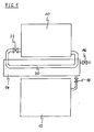
- FIG 1 illustrates a schematic side view of a system with two household appliances according to a first embodiment of the present invention.
- the system includes an oven and a dishwashing machine 12.
- an oven cavity 10 forms an upper part and the dishwashing machine 12 forms a lower part of the system.
- the system comprises at least one household appliance generating waste heat and at least one further household appliance using heated or pre-heated water.
- the system also may include a laundry drier and a washing machine. The described embodiments relate to the system with the oven and dishwashing machine 12.
- a reservoir 14 is arranged between the oven cavity 10 and the dishwashing machine 12.
- the reservoir 14 is provided for storing water for the dishwashing machine 12.
- the reservoir 14 is thermally insulated.
- the container of the reservoir 14 is made of at least one heat insulating material.
- the container of the reservoir 14 is enclosed by at least one heat insulating material.
- the reservoir 14 comprises an inlet valve 16 and an outlet valve 18.
- the inlet valve 16 is connected to an upper portion of the reservoir 14 and connectable to a water supply system.
- the outlet valve 18 is interconnected between a lower portion of the reservoir 14 and the dishwashing machine 12.
- an air pipe 20 is connected to the oven cavity 10. Both ends of said air pipe 20 are connected to the oven cavity 10, so that the air pipe 20 and the oven cavity 10 form a closed loop. A substantial portion of the air pipe 20 extends through the internal space of the reservoir 14. Between the oven cavity 10 and the reservoir 14 the air pipe 20 comprises an air valve 22. Alternatively, the integrated system comprises two or more parallel air pipes 20.
- the reservoir 14 and the air pipe 20 within the reservoir 14 form a heat exchanger, i.e. a water-to-air heat exchanger.
- Said heat exchanger is provided for heating water in the reservoir 12 by hot air in the air pipe 20.
- the hot air is produced in the oven cavity 10.
- the waste heat of the oven cavity 10 is used for heating the water in the reservoir 14.
- the waste heat of the oven cavity 10 is used after the cooking procedure in the oven cavity 10 has been finished.
- the temperature of the heat in the oven cavity 10 is about between 150°C and 200°C.
- the waste heat within an air duct can be used. Said air duct play a similar role like the oven cavity 10 described above. If the waste heat generating household appliance is a laundry drier instead of the oven, then the air duct of said laundry drier can be used in similar way as the cavity 10 of the oven.
- At least one fan which is not shown in FIG 1 , may be interconnected within the air pipe 20.
- said fan may be arranged between the cavity 10 and/or the air duct on the one hand and the reservoir 14 on the other hand. The fan increases the velocity and the turbulence of the air, so that the efficiency of the heat exchanger is improved.
- the procedure of reusing the waste heat of the oven cavity 10 is described hereinafter. Said procedure can be performed manually by the user.
- the system comprises temperature indicators for displaying the temperatures in the oven cavity 10 and in the reservoir 14. Further, said procedure can be performed automatically by a control unit.
- Said control unit comprises electric, electronic and/or mechanic elements.
- the inlet valve 16 is opened.
- water is loaded into the reservoir 14 from the water supply.
- the air valve 22 is opened, so that hot air from the oven cavity 10 flows through the air pipe 20.
- the hot air is blown by a fan of the oven cavity 10 and/or by a special fan arranged within the air pipe 20 behind the air valve 22.
- the hot air warms up the water in the reservoir 14.
- the hot air itself is cooled down.
- the oven cavity 10 is also cooled down.
- the dishwashing machine 12 can use the water in the reservoir 14 without using its own heater.
- the outlet valve 18 is opened in order to convey the water to the dishwashing machine 12.
- the water in the reservoir 14 is pre-heated, so that the heater of the dishwashing machine 12 heats up the water to its predetermined end temperature.
- the outlet valve 18 is opened at first and then the water is completely heated by the dishwashing machine 12.
- the procedure as described above can also be applied to the system with the laundry drier instead of the oven.
- the air duct has a similar function as the oven cavity 10.
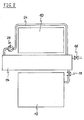
- FIG 2 illustrates a schematic side view of a system with two household appliances according to a second embodiment of the present invention.
- the system includes also the oven and the dishwashing machine 12, wherein the oven cavity 10 forms the upper part and the dishwashing machine 12 forms the lower part of the system.
- the reservoir 14 is arranged between the oven cavity 10 and the dishwashing machine 12.
- the reservoir 14 is also provided for storing water for the dishwashing machine 12.
- the reservoir 14 is thermally insulated.
- the container of the reservoir 14 is either made of at least one heat insulating material or enclosed by at least one heat insulating material.
- the reservoir 14 comprises the inlet valve 16 and the outlet valve 18.
- the inlet valve 16 is connected to the upper portion of the reservoir 14 and connectable to the water supply system.
- the outlet valve 18 is interconnected between the lower portion of the reservoir 14 and the dishwashing machine 12.
- a water pipe 24 is connected to the reservoir 14. Both ends of said water pipe 24 are connected to the reservoir 14, so that the water pipe 24 and the reservoir 14 form a closed loop.
- a water pump 26 is interconnected in the water pipe 24 near the reservoir 14.
- the water pipe 24 encloses the oven cavity 10, so that the water circulates around the oven cavity 10.
- the water pipe 24 at the oven cavity 10 has a serpentine form.
- the water pipe 24 may comprise more parallel water pipes 24 enclosing the oven cavity 10.
- the oven cavity 10 and the water pipe 24 at the oven cavity 10 form a heat exchanger, i.e. a water-to-air heat exchanger.
- Said heat exchanger is provided for heating water in the water pipe 24 by the hot air in the oven cavity 10.
- the hot air is produced in the oven cavity 10.
- the waste heat of the oven cavity 10 is used for heating the water in the water pipe 24.
- the waste heat of the oven cavity 10 is used after the cooking procedure in the oven cavity 10 has been finished.
- the temperature of the heat in the oven cavity 10 is about between 150°C and 200°C.
- the waste heat within an air duct can be used. Said air duct play a similar role like the oven cavity 10 described above. If the household appliance generating the waste heat is a laundry drier instead of the oven, then the air duct of said laundry drier can be used in similar way as the cavity 10 of the oven.
- the heat exchanger may comprise at least one propeller, which is not shown in FIG 2 , within the water pipe 24 and/or the reservoir 14 in order to increase the water turbulence. This improves the efficiency of the heat exchanger.
- the procedure of reusing the waste heat of the oven cavity 10 is described hereinafter. Said procedure can be performed manually by the user.
- the system comprises temperature indicators for displaying the temperatures in the oven cavity 10 and in the reservoir 14. Further, said procedure can be performed automatically by the control unit comprising electric, electronic and/or mechanic elements.
- the inlet valve 16 is opened, and water is loaded into the reservoir 14 from the water supply.
- the water pump 26 is switched on, and water from the reservoir 14 flows through the water pipe 24. Said water circulates through the water pipe 24 and the reservoir 14.
- the hot air in the oven cavity 10 warms up the water in the water pipe 24.
- the water in the reservoir 14 is heated. Otherwise the hot air itself is cooled down by the water.
- the oven cavity 10 is cooled down faster as without the water pipe 24.
- the dishwashing machine 12 can directly use the water in the reservoir 14 without using its own heater. Then, the outlet valve 18 is opened in order to convey the water to the dishwashing machine 12.
- the water in the reservoir 14 and water pipe 24 is only pre-heated, so that the heater of the dishwashing machine 12 heats up the water to its predetermined end temperature.
- the outlet valve 18 is opened at first and then the water is completely heated by the dishwashing machine 12.
- the above procedure can also be applied to the system with the laundry drier instead of the oven.
- the air duct has a similar function as the oven cavity 10.
- the system according to the invention comprises at least two heat generating household appliances.
- the invention is not restricted to the integrated system with the oven and the dishwashing machine 12. Instead of the oven other household appliances generating waste heat can be used. Instead of the dishwashing machine 12 each other household appliance requiring heated or pre-heated water can be used.
- the reservoir 14 has the shape of a frustum of pyramid and the outlet valve 18 is arranged in a low position of said reservoir 14.
- the reservoir 14 can be completely emptied.
- the reservoir 14 comprises at least one further outlet valve.
- the user can take heated or pre-heated water directly from the reservoir 14.
- the further outlet valve can be connected to an external household appliance requiring heated or preheated water.
- the integrated system according to the present invention allows the saving of energy, since the waste heat of the oven cavity 10 and/or the air duct is used for pre-heating the water of the dishwashing machine 12. Further, the oven cavity 10 or the air duct is cooled faster than a conventional cavity or air duct, respectively. The food cooked in the oven cavity 10 is also cooled faster as in a conventional cavity. Thus, the food can faster be served, eaten and put into refrigerator or freezer.
Landscapes
- Engineering & Computer Science (AREA)
- Textile Engineering (AREA)
- Washing And Drying Of Tableware (AREA)
- Detail Structures Of Washing Machines And Dryers (AREA)
Priority Applications (2)
| Application Number | Priority Date | Filing Date | Title |
|---|---|---|---|
| EP08021578A EP2196126A1 (de) | 2008-12-12 | 2008-12-12 | System mit mindestens zwei Haushaltsgeräten |
| EP11179298A EP2412287A1 (de) | 2008-12-12 | 2008-12-12 | System mit mindestens zwei Haushaltsgeräten und Verfahren |
Applications Claiming Priority (1)
| Application Number | Priority Date | Filing Date | Title |
|---|---|---|---|
| EP08021578A EP2196126A1 (de) | 2008-12-12 | 2008-12-12 | System mit mindestens zwei Haushaltsgeräten |
Publications (1)
| Publication Number | Publication Date |
|---|---|
| EP2196126A1 true EP2196126A1 (de) | 2010-06-16 |
Family
ID=40612172
Family Applications (2)
| Application Number | Title | Priority Date | Filing Date |
|---|---|---|---|
| EP08021578A Withdrawn EP2196126A1 (de) | 2008-12-12 | 2008-12-12 | System mit mindestens zwei Haushaltsgeräten |
| EP11179298A Withdrawn EP2412287A1 (de) | 2008-12-12 | 2008-12-12 | System mit mindestens zwei Haushaltsgeräten und Verfahren |
Family Applications After (1)
| Application Number | Title | Priority Date | Filing Date |
|---|---|---|---|
| EP11179298A Withdrawn EP2412287A1 (de) | 2008-12-12 | 2008-12-12 | System mit mindestens zwei Haushaltsgeräten und Verfahren |
Country Status (1)
| Country | Link |
|---|---|
| EP (2) | EP2196126A1 (de) |
Cited By (3)
| Publication number | Priority date | Publication date | Assignee | Title |
|---|---|---|---|---|
| EP2554740A3 (de) * | 2011-08-01 | 2013-07-31 | Samsung Electronics Co., Ltd. | Trocknungsvorrichtung und Waschmaschine damit und Steuerungsverfahren dafür |
| US20170167750A1 (en) * | 2015-12-14 | 2017-06-15 | Advanced Digital Broadcast S.A. | System and method for reducing energy consumption by a medium heating device |
| EP3865042A1 (de) | 2020-02-17 | 2021-08-18 | Renta Elektrik ev Aletleri San.ve Dis Tic.Ltd.Sti. | Wärmerückgewinnungsofen mit geschirrspüler |
Citations (6)
| Publication number | Priority date | Publication date | Assignee | Title |
|---|---|---|---|---|
| DE2161495A1 (de) * | 1971-12-10 | 1973-06-20 | Rhein Westfael Elect Werk Ag | Waermerueckgewinnungsanlage |
| FR2289658A1 (fr) * | 1974-10-25 | 1976-05-28 | Bosch Siemens Hausgeraete | Machine de lavage et de sechage comportant en combinaison une machine a laver entierement automatique et un sechoir a condensation |
| EP1029961A2 (de) | 1999-02-16 | 2000-08-23 | IAR-SILTAL S.p.A. | Kombinierte Waschmaschine |
| DE10045074A1 (de) | 2000-09-12 | 2002-03-28 | Bsh Bosch Siemens Hausgeraete | Haushaltsgeräte mit Wärmespeicher |
| EP1548173A1 (de) * | 2003-12-23 | 2005-06-29 | CANDY S.p.A. | Haushalt-Waschmaschine und Trockner, die miteinander verbunden werden können, entsprechende gemeinsame Installation und entsprechendes Verfahren zum Waschen und Trocknen |
| WO2009020309A1 (en) * | 2007-08-06 | 2009-02-12 | Lg Electronics Inc. | Washing-drying system having washer and dryer and method of controlling water supply for the same |
-
2008
- 2008-12-12 EP EP08021578A patent/EP2196126A1/de not_active Withdrawn
- 2008-12-12 EP EP11179298A patent/EP2412287A1/de not_active Withdrawn
Patent Citations (6)
| Publication number | Priority date | Publication date | Assignee | Title |
|---|---|---|---|---|
| DE2161495A1 (de) * | 1971-12-10 | 1973-06-20 | Rhein Westfael Elect Werk Ag | Waermerueckgewinnungsanlage |
| FR2289658A1 (fr) * | 1974-10-25 | 1976-05-28 | Bosch Siemens Hausgeraete | Machine de lavage et de sechage comportant en combinaison une machine a laver entierement automatique et un sechoir a condensation |
| EP1029961A2 (de) | 1999-02-16 | 2000-08-23 | IAR-SILTAL S.p.A. | Kombinierte Waschmaschine |
| DE10045074A1 (de) | 2000-09-12 | 2002-03-28 | Bsh Bosch Siemens Hausgeraete | Haushaltsgeräte mit Wärmespeicher |
| EP1548173A1 (de) * | 2003-12-23 | 2005-06-29 | CANDY S.p.A. | Haushalt-Waschmaschine und Trockner, die miteinander verbunden werden können, entsprechende gemeinsame Installation und entsprechendes Verfahren zum Waschen und Trocknen |
| WO2009020309A1 (en) * | 2007-08-06 | 2009-02-12 | Lg Electronics Inc. | Washing-drying system having washer and dryer and method of controlling water supply for the same |
Cited By (5)
| Publication number | Priority date | Publication date | Assignee | Title |
|---|---|---|---|---|
| EP2554740A3 (de) * | 2011-08-01 | 2013-07-31 | Samsung Electronics Co., Ltd. | Trocknungsvorrichtung und Waschmaschine damit und Steuerungsverfahren dafür |
| US9657432B2 (en) | 2011-08-01 | 2017-05-23 | Samsung Electronics Co., Ltd. | Drying apparatus and washing machine having the same and control method thereof |
| US20170167750A1 (en) * | 2015-12-14 | 2017-06-15 | Advanced Digital Broadcast S.A. | System and method for reducing energy consumption by a medium heating device |
| US10451308B2 (en) * | 2015-12-14 | 2019-10-22 | Advanced Digital Broadcast S.A. | System and method for reducing energy consumption by a medium heating device |
| EP3865042A1 (de) | 2020-02-17 | 2021-08-18 | Renta Elektrik ev Aletleri San.ve Dis Tic.Ltd.Sti. | Wärmerückgewinnungsofen mit geschirrspüler |
Also Published As
| Publication number | Publication date |
|---|---|
| EP2412287A1 (de) | 2012-02-01 |
Similar Documents
| Publication | Publication Date | Title |
|---|---|---|
| US8946604B2 (en) | Cooking oven with at least one convection heating device | |
| CN214510734U (zh) | 烹饪器具 | |
| EP2784401A1 (de) | Vorrichtung zur Abgabe von heißem Wasser | |
| EP2196126A1 (de) | System mit mindestens zwei Haushaltsgeräten | |
| CN112586973A (zh) | 烹饪器具及其控制方法、计算机可读存储介质及处理器 | |
| CN109199083A (zh) | 一种蒸箱及其工作控制方法 | |
| US20110179830A1 (en) | Washing appliance | |
| CN106580059B (zh) | 电烹饪器的控制方法、装置及电烹饪器 | |
| ES2806003T3 (es) | Método para controlar un aparato de cocción | |
| AU2019400039B2 (en) | Method for controlling a steam generating system for a domestic steam cooking oven and steam generating system | |
| EP3865042B1 (de) | Wärmerückgewinnungsofen mit geschirrspüler | |
| CN107997610B (zh) | 一种蒸箱过温系统及其工作控制方法 | |
| EP1690489A3 (de) | Geschirrspülmaschine | |
| WO2018202415A1 (en) | A household appliance comprising a heat pump | |
| EP2594688A1 (de) | Wäschetrockner mit Wärmepumpensystem | |
| CN207613649U (zh) | 一种蒸箱过温系统 | |
| CN207627036U (zh) | 一种蒸箱 | |
| CN217816911U (zh) | 一种集成灶 | |
| CN201929690U (zh) | 一种烹饪装置 | |
| CN214678598U (zh) | 一种快速蒸汽发生装置及蒸汽烹饪设备 | |
| CN210320603U (zh) | 一种零冷水热水系统 | |
| KR100757857B1 (ko) | 조리용 가스랜지의 폐열을 이용한 난방시스템 | |
| KR200389074Y1 (ko) | 가스레인지의 폐열을 이용한 온수장치 | |
| JP2008267616A (ja) | 家庭内熱エネルギ効率利用システム | |
| CN201492712U (zh) | 集成灶消毒柜热风内循环结构 |
Legal Events
| Date | Code | Title | Description |
|---|---|---|---|
| PUAI | Public reference made under article 153(3) epc to a published international application that has entered the european phase |
Free format text: ORIGINAL CODE: 0009012 |
|
| 17P | Request for examination filed |
Effective date: 20090814 |
|
| AK | Designated contracting states |
Kind code of ref document: A1 Designated state(s): AT BE BG CH CY CZ DE DK EE ES FI FR GB GR HR HU IE IS IT LI LT LU LV MC MT NL NO PL PT RO SE SI SK TR |
|
| AX | Request for extension of the european patent |
Extension state: AL BA MK RS |
|
| AKX | Designation fees paid |
Designated state(s): AT BE BG CH CY CZ DE DK EE ES FI FR GB GR HR HU IE IS IT LI LT LU LV MC MT NL NO PL PT RO SE SI SK TR |
|
| RAP1 | Party data changed (applicant data changed or rights of an application transferred) |
Owner name: ELECTROLUX HOME PRODUCTS CORPORATION N.V. |
|
| RAP1 | Party data changed (applicant data changed or rights of an application transferred) |
Owner name: ELECTROLUX HOME PRODUCTS CORPORATION N.V. |
|
| GRAP | Despatch of communication of intention to grant a patent |
Free format text: ORIGINAL CODE: EPIDOSNIGR1 |
|
| INTG | Intention to grant announced |
Effective date: 20161005 |
|
| STAA | Information on the status of an ep patent application or granted ep patent |
Free format text: STATUS: THE APPLICATION IS DEEMED TO BE WITHDRAWN |
|
| 18D | Application deemed to be withdrawn |
Effective date: 20170216 |