EP2196165A1 - Instrument pour le dévissage d'une vis de liaison d'un implant dentaire - Google Patents
Instrument pour le dévissage d'une vis de liaison d'un implant dentaire Download PDFInfo
- Publication number
- EP2196165A1 EP2196165A1 EP09014506A EP09014506A EP2196165A1 EP 2196165 A1 EP2196165 A1 EP 2196165A1 EP 09014506 A EP09014506 A EP 09014506A EP 09014506 A EP09014506 A EP 09014506A EP 2196165 A1 EP2196165 A1 EP 2196165A1
- Authority
- EP
- European Patent Office
- Prior art keywords
- instrument
- region
- longitudinal axis
- screw
- holding
- Prior art date
- Legal status (The legal status is an assumption and is not a legal conclusion. Google has not performed a legal analysis and makes no representation as to the accuracy of the status listed.)
- Withdrawn
Links
- 239000004053 dental implant Substances 0.000 title claims description 21
- 229910001220 stainless steel Inorganic materials 0.000 claims description 5
- 239000010935 stainless steel Substances 0.000 claims description 5
- 239000007943 implant Substances 0.000 abstract description 18
- 238000000034 method Methods 0.000 abstract description 3
- 238000004873 anchoring Methods 0.000 description 26
- 210000000988 bone and bone Anatomy 0.000 description 6
- 230000005540 biological transmission Effects 0.000 description 5
- 230000007704 transition Effects 0.000 description 5
- 238000004519 manufacturing process Methods 0.000 description 4
- 239000000463 material Substances 0.000 description 3
- 230000006735 deficit Effects 0.000 description 2
- 230000001954 sterilising effect Effects 0.000 description 2
- 238000004659 sterilization and disinfection Methods 0.000 description 2
- RTAQQCXQSZGOHL-UHFFFAOYSA-N Titanium Chemical compound [Ti] RTAQQCXQSZGOHL-UHFFFAOYSA-N 0.000 description 1
- 230000002411 adverse Effects 0.000 description 1
- 239000000919 ceramic Substances 0.000 description 1
- 238000004140 cleaning Methods 0.000 description 1
- 230000007423 decrease Effects 0.000 description 1
- 230000001419 dependent effect Effects 0.000 description 1
- 238000005553 drilling Methods 0.000 description 1
- 238000002513 implantation Methods 0.000 description 1
- 229910052751 metal Inorganic materials 0.000 description 1
- 239000002184 metal Substances 0.000 description 1
- 238000003825 pressing Methods 0.000 description 1
- 238000007493 shaping process Methods 0.000 description 1
- 239000007787 solid Substances 0.000 description 1
- 239000010936 titanium Substances 0.000 description 1
- 229910052719 titanium Inorganic materials 0.000 description 1
Images


Classifications
-
- A—HUMAN NECESSITIES
- A61—MEDICAL OR VETERINARY SCIENCE; HYGIENE
- A61C—DENTISTRY; APPARATUS OR METHODS FOR ORAL OR DENTAL HYGIENE
- A61C8/00—Means to be fixed to the jaw-bone for consolidating natural teeth or for fixing dental prostheses thereon; Dental implants; Implanting tools
- A61C8/0089—Implanting tools or instruments
Definitions
- the present invention relates to an instrument for releasing a screw stump, in particular for releasing a screw stump from a dental implant.
- dental implants as an artificial replacement for tooth roots has become established in the field of dental prosthetics in recent years.
- dental implants in particular, the helical implants have proven.
- dental implants made of titanium or different ceramics are used.
- Screw-shaped dental implants usually consist of an anchoring part for anchoring the implant in the bone and a mounting part on which a superstructure, for example a crown, can be fastened. If anchoring part and body part are formed as a single component, one speaks of a one-piece implant. Alternatively, two-part implants are often used in which anchoring part and body part are formed as two separate components. During implantation, the helical anchoring part is screwed into a suitable borehole in the bone. Later, the supraconstruction will be attached to the abutment of the implant.
- anchoring part and the abutment part are usually connected to each other by means of a connecting screw.
- anchoring and body part each have an internal thread.
- the body part is attached to the anchoring part, so that the internal thread of the body part lies exactly in the extension of that of the anchoring part and screwed the connecting screw.
- a corresponding dental implant system is, for example, in EP 1 728 486 describe, in which case the anchoring and body part have an inner or outer octagon, to prevent rotation between the two implant parts.
- the only way to remove the screw stub from the internal thread is to drill out the screw stub.
- a hole in the screw stub is drilled along the central axis of the screw stub, which is slightly smaller than the diameter of the screw.
- This method is relatively delicate, as it can easily damage the anchoring and / or body part: If not drilled exactly in the central axis of the screw stub, a part of the internal thread can be removed; and if drilled too deep, the anchoring part in the extension of the connecting bolt will be damaged. A Inaccuracy can thus have a massive impact on the stability of the implant, and a very accurate drill guide is essential.
- the part of the anchoring screw that is outside the hole, in particular the thread must be removed from the anchoring and body part. Overall, this procedure is very time-consuming and error-prone.
- the instrument according to the invention for releasing a screw stump comprises a holding area, a front area and a middle area.
- the instrument has a centrally arranged longitudinal axis A.
- the holding region, the central region, the front region and the active region have a common, centrally arranged longitudinal axis, which coincides with the longitudinal axis A of the instrument.
- the holding area is used to hold the instrument.
- the central area connects the front area with the holding area.
- the front region is substantially circular cylindrical and has an effective range pointing away from the holding region, which has a jacket-shaped outer surface and three to six mandrel-shaped teeth having. These thorn-shaped prongs serve to engage in an upper end surface of the screw stub to be loosened.
- the thorn-shaped prongs of the active region are distributed uniformly in the circumferential direction about the longitudinal axis of the instrument.
- the instrument according to the invention serves, in particular, to detach a screw stub screwed in at least partially into a dental implant from the latter.
- the instrument according to the invention has mandrel-shaped prongs for engagement in an upper end face of the screw stump.
- screw stump can be unscrewed out of the implant.
- the thorn-shaped prongs are not eingingerammt in the upper end surface, but the torque transmission takes place due to friction on the surface of the screw stub. In this way, the burden on the dental implant and also for the surrounding bone tissue is kept as small as possible and an impairment is avoided.
- the substantially circular cylindrical front region is designed such that it can be easily inserted into the internal thread in the anchoring and mounting part of the implant.
- the diameter of the front region is chosen only slightly smaller than that of the internal thread, so that the instrument is guided when loosening the screw stump through the inner walls of the implant parts.
- the tips of the thorn-shaped prongs lie on the jacket-shaped outer surface of the effective region.
- the tips of the thorn-shaped prongs may also lie further inwards.
- the holding region and / or the central region are formed substantially circular cylindrical.
- the central region of the instrument according to the invention can serve as a guide region, the middle region being guided by the essentially circular cylindrical inner surfaces of the anchoring and mounting part of the implant. This considerably simplifies the handling of the instrument.
- the effective range of the instrument has four mandrel-shaped prongs. This arrangement allows an optimal transmission of torque to the screw stub for releasing the same.
- the second and third, referred to as "flat" surfaces are not curved in contrast to the first envelope-shaped surface.
- the term “even” is used here and in the further course of this application text accordingly.
- This serrated shape allows a particularly good torque transmission of the instrument according to the invention on the screw stump.
- the production of the front region which is preferably carried out by grinding a substantially cylindrical pin, much easier than other prongs shapes.
- the stability of the teeth is also very good.
- the second, parallel to the longitudinal axis A surface of a tine is in the counterclockwise direction in front of the third, inclined surface of the same tine.
- the second, parallel to the longitudinal axis A surface of a tine is thus in the counterclockwise direction in front of the third inclined surface of the same tine, if, if one proceeds from the second surface in a counterclockwise direction, to the third surface of the same tine.
- the second surface lying parallel to the longitudinal axis A and the inclined third surface are arranged such that the surface lying parallel to the longitudinal axis A precedes when loosening the screw stub. If thus, to loosen the screw stump the instrument must be rotated in the counterclockwise direction, which is the case with the threads common today, then the second, lying parallel to the longitudinal axis A surface of a tine preferably located in front of the third, inclined surface of the same axis.
- the transmission of torque to the screw stump can be optimized so that as little force must be expended and the burden on the implant and the surrounding bone tissue can be minimized.
- the third, inclined surface is inclined at an angle ⁇ of 30-60 °, preferably 45 °, with respect to the longitudinal axis A of the instrument.
- the two angles ⁇ and ⁇ are independently 10 to 45 °, more preferably 20 to 30 °.
- the two angles ⁇ and ⁇ are independently 10 to 45 °, more preferably 20 to 30 °.
- the holding region of the instrument according to the invention is designed such that a torque can be transmitted to the instrument by hand. This allows a simple unscrewing of the screw stub without much effort and without the need for another tool.
- the holding region of the instrument according to the invention is designed such that a torque can be transmitted to the instrument by means of a ratchet. As a result, larger torques can be transmitted to the instrument according to the invention and thus to the screw stub.
- the material and shape of the instrument according to the invention are chosen such that the instrument can be sterilized after use and later used again to detach a screw stump, in particular from a dental implant. Particular care must be taken in shaping that the instrument does not undercut or otherwise interfere with Sterilization has difficult to access areas.
- the instrument may also be intended for single use.
- At least the effective range of the instrument according to the invention consists of a solid, easily sterilizable material, in particular of a metal. More preferably, at least the active region of stainless steel, for example, from Cronidur ®. Preferably, not only the effective range, but the entire instrument consists of such a material, in particular stainless steel. As a result, the production, cleaning and sterilization of the instrument according to the invention is substantially simplified.
- the present invention relates to the use of an inventive instrument for releasing a screw stump, in particular for releasing a screw stump from a dental implant.
- the use of the instrument according to the invention is particularly advantageous when the upper end surface of the screw stump is very smooth.
- the screw stump can be removed from the implant by means of the instrument according to the invention without adversely affecting the implant and the surrounding bone tissue.
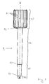
- FIG. 1 shows an inventive instrument 1 for releasing a screw stub.
- the instrument 1 shown is made of stainless steel and has a holding region 10, a central region 15 and a front region 20 and has a centrally arranged longitudinal axis A.
- the front region 20 has an effective region 25 pointing away from the holding region 10.
- the holding region 10, the middle region 15 and the front region 20 are formed substantially circular cylindrical, wherein the diameter decreases from the holding region 10 via the central region 15 to the front region 20 in each case.
- the diameter of the middle region is selected such that the central region is guided through the implant upon release of the screw stump.
- the dimensions of the front area are also adapted to the dimensions of screw stump and anchoring and body part.
- a first transition region 12 is arranged, whose diameter changes from that of the holding region 10 into that of the middle region 15.
- a second transition region 17 is arranged, whose diameter transitions from that of the middle region 15 into that of the front region 20.
- the instrument 1 shown a third transition region 22, which adjoins the effective region 25.
- the holding portion 10 has a plurality of lamellar, parallel to the longitudinal axis A of the instrument 1 extending projections 11, which facilitate the holding of the instrument 1 and prevent slipping.
- These lamellar projections 11 have no undercuts, so that the instrument 1 can be sterilized well. In addition, they are designed such that a suitable tool can cooperate with the projections 11.
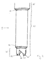
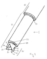
- FIGS. 2 to 4 show enlarged side views and oblique plan views of the central region 15, the front portion 20 and the active region 25 of the instrument 1.
- the in the FIGS. 1 to 5 shown active region 25 has four thorn-shaped prongs 30, 35, 40 and 45, which are distributed uniformly in the circumferential direction about the longitudinal axis A ( FIG. 2 ).
- the tips 31, 36, 41 and 46 of the four mandrel-shaped prongs 30, 35, 40 and 45 lie on the jacket-shaped outer surface 27 of the active region 25 (FIG. FIG. 3 ).
- Each of the four mandrel-shaped prongs 30, 35, 40 and 45 has substantially three surfaces which meet at the tip 31, 36, 41 or 46 ( FIG.
- a first, curved surface 42, 47 coincides with the jacket-shaped outer surface 27 of the effective region 25
- a second, planar surface 33, 38 is parallel to the longitudinal axis A of the instrument 1 and a third, planar surface 24, 39, 44, 49 is inclined relative to the longitudinal axis A by an angle ⁇ .
- FIG. 5 schematically shows a cross section through an inserted into a jaw bone 90 dental implant 100.
- the dental implant 100 comprises an anchoring part 80 and a mounting part 70 which is attached to the anchoring part 80.
- the anchoring part 80 has Both the body part 70 and the anchoring part 80 each have an internal thread 72, 82, wherein the internal thread 72 of the mounting part 70 is located exactly in the axial extension of the internal thread 82 of the anchoring part.
- the internal thread 72, 82 is a screw stub 60, so a broken part of a connecting screw.
- the screw stump 60 has an external thread 64 for anchoring in the internal thread 72, 82 of the dental implant 100.
- the screw stub 60 has a substantially straight upper end surface 62.
- the instrument 1 according to the invention, of which the front region 20, the third transition region 22 and the effective region 25 with its four mandrel-shaped prongs 30, 35, 40, 45 can be seen in the figure, is used to remove the screw stump 60 from the internal thread 72, 82 to remove.
- the four mandrel-shaped prongs 30, 35, 40, 45 of the active region 25 are pressed against the upper end surface 62 of the screw stump 60.
- a torque can be transmitted to the screw stump 60 and this can be released from the dental implant 100.
Landscapes
- Health & Medical Sciences (AREA)
- Oral & Maxillofacial Surgery (AREA)
- Orthopedic Medicine & Surgery (AREA)
- Dentistry (AREA)
- Epidemiology (AREA)
- Life Sciences & Earth Sciences (AREA)
- Animal Behavior & Ethology (AREA)
- General Health & Medical Sciences (AREA)
- Public Health (AREA)
- Veterinary Medicine (AREA)
- Dental Prosthetics (AREA)
Applications Claiming Priority (1)
| Application Number | Priority Date | Filing Date | Title |
|---|---|---|---|
| CH01940/08A CH700097A1 (de) | 2008-12-10 | 2008-12-10 | Instrument zum Lösen eines Schraubenstumpfes einer Verbindungsschraube eines Zahnimplantats. |
Publications (1)
| Publication Number | Publication Date |
|---|---|
| EP2196165A1 true EP2196165A1 (fr) | 2010-06-16 |
Family
ID=40568287
Family Applications (1)
| Application Number | Title | Priority Date | Filing Date |
|---|---|---|---|
| EP09014506A Withdrawn EP2196165A1 (fr) | 2008-12-10 | 2009-11-20 | Instrument pour le dévissage d'une vis de liaison d'un implant dentaire |
Country Status (4)
| Country | Link |
|---|---|
| US (1) | US20100143865A1 (fr) |
| EP (1) | EP2196165A1 (fr) |
| JP (1) | JP2010137052A (fr) |
| CH (1) | CH700097A1 (fr) |
Families Citing this family (5)
| Publication number | Priority date | Publication date | Assignee | Title |
|---|---|---|---|---|
| EP2722019A4 (fr) * | 2011-06-15 | 2015-06-03 | Neobiotech Co Ltd | Trépan pour retirer une vis de couplage d'implant et douille de guidage de celui-ci |
| KR101643351B1 (ko) * | 2014-07-15 | 2016-08-10 | 오스템임플란트 주식회사 | 어버트먼트 스크류 제거 드릴 및 어버트먼트 스크류 제거 장치 |
| KR101566457B1 (ko) * | 2015-03-03 | 2015-11-05 | 주식회사 메가젠임플란트 | 어버트먼트 제거 드릴 및 이를 구비하는 어버트먼트 제거 장치 |
| WO2021165948A1 (fr) * | 2020-02-19 | 2021-08-26 | Telcon Diamond Ltd. | Système et procédé de retrait de vis de restauration dentaire |
| JP7824295B2 (ja) | 2023-01-17 | 2026-03-04 | 憲治 井汲 | アバットメントスクリュー除去器具および補助器具 |
Citations (6)
| Publication number | Priority date | Publication date | Assignee | Title |
|---|---|---|---|---|
| WO2000027300A1 (fr) * | 1998-11-11 | 2000-05-18 | Nobel Biocare Ab (Publ) | Implant filete, sa disposition et son procede de fixation |
| US6247933B1 (en) | 1999-12-10 | 2001-06-19 | Sulzer Dental Inc. | Dental implant delivery system |
| WO2001050978A1 (fr) * | 2000-01-14 | 2001-07-19 | Nobel Biocare Ab | Systeme de pose d'implant universel |
| US6312260B1 (en) * | 1998-08-12 | 2001-11-06 | Nobel Biocare Ab | One-step threaded implant |
| WO2002080804A1 (fr) * | 2001-04-05 | 2002-10-17 | Neoss Limited | Implant |
| EP1728486A1 (fr) | 2005-06-03 | 2006-12-06 | Straumann Holding AG | Connexion pour un système d'implant dentaire à plusieurs parties |
Family Cites Families (9)
| Publication number | Priority date | Publication date | Assignee | Title |
|---|---|---|---|---|
| US4270418A (en) * | 1979-12-12 | 1981-06-02 | Helen I. Shephard | Fluted tool |
| US4688315A (en) * | 1986-05-28 | 1987-08-25 | Jannke Thomas E | Screw extractor and method of using same |
| US4713990A (en) * | 1986-07-18 | 1987-12-22 | Poling Denzil C | Bolt extracting tool |
| US5865078A (en) * | 1995-11-03 | 1999-02-02 | Langford; Don | Sports shoe spike removal tool |
| US5951287A (en) * | 1997-04-17 | 1999-09-14 | Hawkinson; Roy T. | Dental implant failed fastener recovery systems, devices and methods |
| US6416324B1 (en) * | 1999-12-10 | 2002-07-09 | Sulzer Dental Inc. | One step dental implant delivery system |
| US6280197B1 (en) * | 2000-01-04 | 2001-08-28 | Doron Benado | Method and apparatus for the withdrawal of dental post |
| US7594455B2 (en) * | 2007-10-23 | 2009-09-29 | Sears Brands, Llc | Fastener removing tool |
| US20090317771A1 (en) * | 2008-06-20 | 2009-12-24 | Biotechnology Institute, I Mas D, S.L. | Implant removal tool |
-
2008
- 2008-12-10 CH CH01940/08A patent/CH700097A1/de not_active Application Discontinuation
-
2009
- 2009-11-20 EP EP09014506A patent/EP2196165A1/fr not_active Withdrawn
- 2009-12-07 JP JP2009277528A patent/JP2010137052A/ja active Pending
- 2009-12-10 US US12/635,275 patent/US20100143865A1/en not_active Abandoned
Patent Citations (6)
| Publication number | Priority date | Publication date | Assignee | Title |
|---|---|---|---|---|
| US6312260B1 (en) * | 1998-08-12 | 2001-11-06 | Nobel Biocare Ab | One-step threaded implant |
| WO2000027300A1 (fr) * | 1998-11-11 | 2000-05-18 | Nobel Biocare Ab (Publ) | Implant filete, sa disposition et son procede de fixation |
| US6247933B1 (en) | 1999-12-10 | 2001-06-19 | Sulzer Dental Inc. | Dental implant delivery system |
| WO2001050978A1 (fr) * | 2000-01-14 | 2001-07-19 | Nobel Biocare Ab | Systeme de pose d'implant universel |
| WO2002080804A1 (fr) * | 2001-04-05 | 2002-10-17 | Neoss Limited | Implant |
| EP1728486A1 (fr) | 2005-06-03 | 2006-12-06 | Straumann Holding AG | Connexion pour un système d'implant dentaire à plusieurs parties |
Also Published As
| Publication number | Publication date |
|---|---|
| US20100143865A1 (en) | 2010-06-10 |
| JP2010137052A (ja) | 2010-06-24 |
| CH700097A1 (de) | 2010-06-15 |
Similar Documents
| Publication | Publication Date | Title |
|---|---|---|
| EP2607722B1 (fr) | Vis de liaison pour un implant dentaire | |
| EP0513943B1 (fr) | Implant avec surface de pression | |
| EP2564799B1 (fr) | Clou chirurgical de compression du métatarse | |
| DE3735378A1 (de) | Schraubenimplantat, insbesondere fuer zahnprothesen | |
| EP3223741A1 (fr) | Implant dentaire individuel intra-osseux | |
| EP2674127B1 (fr) | Implant | |
| EP3021782B1 (fr) | Implant dentaire à structure rainurée coronale | |
| DE202012002636U1 (de) | Schraubenimplantat für einen Kieferknochen mit koronalem Kompressionsgewinde und apikalem Selbstschneidgewinde | |
| EP2196165A1 (fr) | Instrument pour le dévissage d'une vis de liaison d'un implant dentaire | |
| EP1462066B1 (fr) | Implant dentaire comportant un faux-moignon incliné | |
| DE102008019489A1 (de) | Medizinprodukt, insbesondere Implantat oder Schraubenkörper mit einem Gewinde zum Einschrauben in einen Knochen | |
| DE10238091A1 (de) | Dentalimplantat mit Verankerungskopf und Schraubkörper | |
| WO1999039653A1 (fr) | Implant dentaire intra-osseux a filetage autotaraudeur | |
| EP1462067A2 (fr) | Implant maxillaire temporaire | |
| CH711879A1 (de) | Dentalimplantatsystem. | |
| DE29716883U1 (de) | Kieferimplantat und Suprastruktur für zahnmedizinische Zwecke zur Halterung eines Zahnersatzes am menschlichen Kiefer | |
| DE102008056104A1 (de) | Schraubenimplantat | |
| DE102019106718A1 (de) | Osteosyntheseplatte zur Fixierung eines Dentalimplantats oder mehrerer Dentalimplantate | |
| WO2003086225A1 (fr) | Pre-implant pour implant dentaire intra-osseux a implanter ulterieurement | |
| EP3914188B1 (fr) | Vis occlusale, système d'implant dentaire et ensemble | |
| DE102006007541A1 (de) | Implantat für Zahnersatzbefestigung | |
| DE102011055106B3 (de) | Hüftprothese | |
| DE102019005042A1 (de) | Anordnung von einem Implantat, einem Abutment und einem Zahnersatz | |
| DE102017101100B4 (de) | Zahnimplantataufbau | |
| WO2016066475A1 (fr) | Système d'implant et procédé d'implantation d'un implant dentaire |
Legal Events
| Date | Code | Title | Description |
|---|---|---|---|
| PUAI | Public reference made under article 153(3) epc to a published international application that has entered the european phase |
Free format text: ORIGINAL CODE: 0009012 |
|
| AK | Designated contracting states |
Kind code of ref document: A1 Designated state(s): AT BE BG CH CY CZ DE DK EE ES FI FR GB GR HR HU IE IS IT LI LT LU LV MC MK MT NL NO PL PT RO SE SI SK SM TR |
|
| AX | Request for extension of the european patent |
Extension state: AL BA RS |
|
| 17P | Request for examination filed |
Effective date: 20101116 |
|
| 17Q | First examination report despatched |
Effective date: 20110117 |
|
| STAA | Information on the status of an ep patent application or granted ep patent |
Free format text: STATUS: THE APPLICATION IS DEEMED TO BE WITHDRAWN |
|
| 18D | Application deemed to be withdrawn |
Effective date: 20140603 |