EP2196335B1 - Système de gonflage de pneus doté d'un joint de roue intégré - Google Patents
Système de gonflage de pneus doté d'un joint de roue intégré Download PDFInfo
- Publication number
- EP2196335B1 EP2196335B1 EP09176648.5A EP09176648A EP2196335B1 EP 2196335 B1 EP2196335 B1 EP 2196335B1 EP 09176648 A EP09176648 A EP 09176648A EP 2196335 B1 EP2196335 B1 EP 2196335B1
- Authority
- EP
- European Patent Office
- Prior art keywords
- seal
- wheel hub
- hub
- air chamber
- axle assembly
- Prior art date
- Legal status (The legal status is an assumption and is not a legal conclusion. Google has not performed a legal analysis and makes no representation as to the accuracy of the status listed.)
- Not-in-force
Links
Images

Classifications
-
- B—PERFORMING OPERATIONS; TRANSPORTING
- B60—VEHICLES IN GENERAL
- B60C—VEHICLE TYRES; TYRE INFLATION; TYRE CHANGING; CONNECTING VALVES TO INFLATABLE ELASTIC BODIES IN GENERAL; DEVICES OR ARRANGEMENTS RELATED TO TYRES
- B60C23/00—Devices for measuring, signalling, controlling, or distributing tyre pressure or temperature, specially adapted for mounting on vehicles; Arrangement of tyre inflating devices on vehicles, e.g. of pumps or of tanks; Tyre cooling arrangements
- B60C23/001—Devices for manually or automatically controlling or distributing tyre pressure whilst the vehicle is moving
- B60C23/003—Devices for manually or automatically controlling or distributing tyre pressure whilst the vehicle is moving comprising rotational joints between vehicle-mounted pressure sources and the tyres
- B60C23/00345—Details of the rotational joints
-
- B—PERFORMING OPERATIONS; TRANSPORTING
- B60—VEHICLES IN GENERAL
- B60C—VEHICLE TYRES; TYRE INFLATION; TYRE CHANGING; CONNECTING VALVES TO INFLATABLE ELASTIC BODIES IN GENERAL; DEVICES OR ARRANGEMENTS RELATED TO TYRES
- B60C23/00—Devices for measuring, signalling, controlling, or distributing tyre pressure or temperature, specially adapted for mounting on vehicles; Arrangement of tyre inflating devices on vehicles, e.g. of pumps or of tanks; Tyre cooling arrangements
- B60C23/001—Devices for manually or automatically controlling or distributing tyre pressure whilst the vehicle is moving
- B60C23/003—Devices for manually or automatically controlling or distributing tyre pressure whilst the vehicle is moving comprising rotational joints between vehicle-mounted pressure sources and the tyres
- B60C23/00309—Devices for manually or automatically controlling or distributing tyre pressure whilst the vehicle is moving comprising rotational joints between vehicle-mounted pressure sources and the tyres characterised by the location of the components, e.g. valves, sealings, conduits or sensors
- B60C23/00318—Devices for manually or automatically controlling or distributing tyre pressure whilst the vehicle is moving comprising rotational joints between vehicle-mounted pressure sources and the tyres characterised by the location of the components, e.g. valves, sealings, conduits or sensors on the wheels or the hubs
-
- B—PERFORMING OPERATIONS; TRANSPORTING
- B60—VEHICLES IN GENERAL
- B60C—VEHICLE TYRES; TYRE INFLATION; TYRE CHANGING; CONNECTING VALVES TO INFLATABLE ELASTIC BODIES IN GENERAL; DEVICES OR ARRANGEMENTS RELATED TO TYRES
- B60C23/00—Devices for measuring, signalling, controlling, or distributing tyre pressure or temperature, specially adapted for mounting on vehicles; Arrangement of tyre inflating devices on vehicles, e.g. of pumps or of tanks; Tyre cooling arrangements
- B60C23/001—Devices for manually or automatically controlling or distributing tyre pressure whilst the vehicle is moving
- B60C23/003—Devices for manually or automatically controlling or distributing tyre pressure whilst the vehicle is moving comprising rotational joints between vehicle-mounted pressure sources and the tyres
- B60C23/00363—Details of sealings
-
- B—PERFORMING OPERATIONS; TRANSPORTING
- B60—VEHICLES IN GENERAL
- B60C—VEHICLE TYRES; TYRE INFLATION; TYRE CHANGING; CONNECTING VALVES TO INFLATABLE ELASTIC BODIES IN GENERAL; DEVICES OR ARRANGEMENTS RELATED TO TYRES
- B60C23/00—Devices for measuring, signalling, controlling, or distributing tyre pressure or temperature, specially adapted for mounting on vehicles; Arrangement of tyre inflating devices on vehicles, e.g. of pumps or of tanks; Tyre cooling arrangements
- B60C23/001—Devices for manually or automatically controlling or distributing tyre pressure whilst the vehicle is moving
- B60C23/003—Devices for manually or automatically controlling or distributing tyre pressure whilst the vehicle is moving comprising rotational joints between vehicle-mounted pressure sources and the tyres
- B60C23/0039—Devices for manually or automatically controlling or distributing tyre pressure whilst the vehicle is moving comprising rotational joints between vehicle-mounted pressure sources and the tyres specially adapted for driven wheels
Definitions
- the subject invention relates to an axle that includes an air passage that forms part of a tire inflation system. More specifically, the air passage is formed at least in part between a rotating wheel hub and a non-rotating component, and is sealed by an integrated seal assembly.
- Tire inflation systems are used on vehicles, such as tractor-trailer vehicles for example, to maintain tire inflation pressures at a desired tire pressure setting.
- the tire inflation system draws pressurized air from on-board air tanks and supplies this air to an under-inflated tire when tire pressure falls below the desired tire pressure setting.
- Air hoses must be routed externally of the axle components and around the outside of the tires. Such a routing configuration takes up a significant amount of packaging space that could otherwise be used for other vehicle components. Further, due to the external mounting, a significant portion of the air hoses is exposed to potentially damaging contact from rocks, debris, etc.
- US 4 804 027 shows an example of a tire inflation system according to the preamble of claim 1.
- An axle assembly includes an air passage for fluid communication with a tire inflation system.
- the axle assembly includes a non-rotating component and a wheel hub supported for rotation relative to the non-rotating component about an axis.
- the air passage is formed at least in part between the wheel hub and the non-rotating component, and is sealed with a seal assembly.
- the wheel hub includes a hub air passage that has a hub inlet and a hub outlet to be fluidly connected to at least one tire.
- the non-rotating component comprises a spindle that rotatably supports the wheel hub.
- An air chamber is formed at least in part between the spindle and the wheel hub. The air chamber receives air flow from an air source and directs air flow into the hub inlet.
- a seal assembly engages the wheel hub to seal the air chamber.
- the seal assembly includes first and second seals that are in sealing engagement with the wheel hub and the non-rotating component.
- the seal assembly comprises a cartridge seal with seal portions that are in contact with the wheel hub and the non-rotating component.
- the seal portions engage each other, and the air chamber is formed between the seal portions.
- the non-rotating component comprises a spindle that rotatably supports the wheel hub and the air chamber is defined in part by a manifold that is fixed to the spindle.
- the manifold includes a first passage to direct air from an air source to the air chamber.
- the seal assembly seals against an inner surface of the wheel hub and an outer surface of the manifold to form the air chamber.
- the manifold also includes a second passage to direct lubricating fluid to the seals.
- the non-rotating component comprises an annular ring that surrounds an inboard end of the wheel hub.
- the air chamber is defined within the annular ring at the inboard end of the wheel hub.
- the seal assembly includes a first seal that engages the annular ring and an outer peripheral surface of the wheel hub and a second seal that engages the annular ring and an inner peripheral surface of the wheel hub to define the air chamber.
- the axle assembly is a drive axle and includes an axle shaft that is driven by a power source.
- the axle shaft is coupled to drive the wheel hub about an axis of rotation relative to the spindle.
- FIG 1 shows a drive axle 10 receiving driving input from a power source 12, such as an engine or electric motor for example.
- the driving input drives an input gear assembly 14 that includes a differential mechanism as known.
- the gear assembly 14 drives axle shafts 16 that are coupled to drive wheel end assemblies 18.
- One example of a wheel end assembly 18 is shown to the left of Figure 1 . It should be understood that the opposite wheel end assembly 18 would be similarly configured.
- the wheel end assembly 18 includes a non-rotating spindle 20 that is mounted to an axle housing 22.
- the axle housing 22 houses the gear assembly 14 and axle shafts 16.
- a wheel hub 24 is rotatably supported on the spindle 20 by bearings 26.
- a tire 28 and associated rim are mounted for rotation with the wheel hub 24 about an axis A.
- a tire inflation system 30 includes an air supply reservoir or tank 32 that is used to supply air to the tires 28 when the tires 28 become under-inflated.
- the tire inflation system 30 includes a control 34 that determines when air is to be supplied and also controls the amount of air supplied as known.
- the control 34 can be automatically activated via an electronic control unit or other similar device to control the amount of air supplied, or the control 34 can be manually actuated by a vehicle operator.
- the control 34 can include various valves, sensors, pressure regulators, etc. as known to control distribution of the air from the tank 32.
- the control 34 is also configured to stop supplying air to a tire if pressure falls below a certain level to prevent the tank 32 from being depleted of air, such as when a tire has experienced a blow-out for example.
- the control 34 supplies air to the wheel end assembly 18 which includes passages that convey the air to the tire 28.
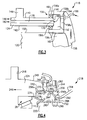
- Figure 2 shows one example of a wheel end assembly 18 as used with the tire inflation system 30.
- the wheel hub 24 includes an outer peripheral surface 40 and an inner peripheral surface 42 that surround the axis of rotation A.
- the wheel hub 24 also includes an inboard end 44 and an outboard end 46 with a mounting flange portion 48 that can be used to mount other brake or wheel structures.
- An air chamber 52 is formed at least in part between the wheel hub 24 and a non-rotating component, such as the spindle 20 for example.
- the spindle 20 includes an outer peripheral surface 50 that is spaced radially inwardly of the inner peripheral surface 42 of the wheel hub 24.
- the air chamber 52 is defined within a space formed between the wheel hub 24 and the spindle 20.
- a seal assembly 56 is integrated into the wheel end assembly 18 to seal the air chamber 52.
- the seal assembly 56 directly seals against the inner peripheral surface 42 of the wheel hub 24.
- a manifold 58 is fixed to the outer peripheral surface 50 of the spindle 20.
- the manifold 58 includes an inner peripheral surface 60 that is seated against the spindle 20 and an outer peripheral surface 62 that is spaced radially inwardly relative to the inner peripheral surface 42 of the wheel hub 24 to define the air chamber 52.
- the manifold 58 and seal assembly 56 are positioned at the inboard end 44 of the wheel hub 24 such that the air chamber 52 is inboard of the wheel bearings 26.
- the manifold 58 includes an inlet port 64 that is connected to the air tank 32 with a conduit or hose 66.
- the manifold includes a first passage 68 that that directs air from the inlet port 64 to the air chamber 52.
- the seal assembly 56 includes at least a first seal 56a and a second seal 56b that is axially spaced from the first seal 56a along the axis A.
- the manifold 58 includes an outlet port 70 that empties into the air chamber 52 at a position between the first 56a and second 56b seals.
- the manifold 58 also includes a second passage 72 that directs lubricating fluid to the seal assembly 56.
- the second passage 72 extends from a lubrication cavity 74 formed between the inboard bearing 26 ( Figure 1 ) and the first seal 56a to a lubrication cavity 76 that is positioned inboard of the second seal 56b.
- a third seal 56c sealingly engages the inner peripheral surface 42 of the wheel hub 24 and the outer peripheral surface 62 of the manifold to seal the lubrication cavity 76. This prevents lubricating fluid from exiting the wheel end assembly 18 at the inboard end 44 of the wheel hub 24.
- the hub passage 78 can be formed through the hub body, hub flange portion 48, through a wheel stud hole, etc.
- the hub passage 78 includes a hub inlet 80 and a hub outlet 82 that is fluidly connected to at least one of the tires 28.
- FIG. 3 shows another example of a wheel end assembly 118 as used with the tire inflation system 30.
- a wheel hub 124 includes an outer peripheral surface 140 and an inner peripheral surface 142 that surround the axis of rotation A.
- the wheel hub 124 also includes an inboard end 144 and an outboard end 146 with a mounting flange portion 148.
- the spindle 120 includes an outer peripheral surface 150 that is spaced radially inwardly of the inner peripheral surface 142 of the wheel hub 124.
- a seal assembly 156 is integrated into the wheel end assembly 118 to seal an air chamber 152. The seal assembly 156 directly seals against the inner peripheral surface 142 of the wheel hub 124.
- the non-rotating component comprises an annular ring 158 is positioned to surround the inboard end 144 of the wheel hub 124 at a position where an ABS tone ring would typically be mounted.
- the annular ring 158 is a stationary, i.e. non-rotating component, which can be fixed to the spindle 120 or to another non-rotating axle or brake component.
- the annular ring 158 has a C-shape cross-section with a vertical wall portion 158a and first 158b and second 158c lateral flange portions that extend axially away from opposing ends of the vertical wall portion 158a.
- the first 158b and second 158c lateral flange portions extend in a direction that is generally parallel to the axis A.
- the first lateral flange portion 158b defines an outer peripheral surface 160 of the annular ring 158 and the second lateral flange portion 158c defines an inner peripheral surface 162 of the annular ring 158.
- the first 158b and second 158c flange portions are positioned in an overlapping relationship with the inboard end 144 of the wheel hub 124.
- the first lateral flange portion 158b is positioned radially outwardly of the outer peripheral surface 140 of the wheel hub 124 and the second lateral flange portion 158c is positioned radially inwardly of the inner peripheral surface 142 of the wheel hub 124.
- the air chamber 152 is formed within the annular ring 158 at the inboard end 144 of the wheel hub 124 at a position that is between the first 158b and second 158c lateral flange portions.
- the vertical wall portion 158a includes an inlet port 164 that is fluidly connected to the air tank 32 with a conduit or hose 166.
- the port 164 directs air into the air chamber 152.
- the wheel hub 124 includes a hub passage 176 that is formed within a body of the hub between the inner 142 and outer 140 peripheral surfaces.
- the hub passage 176 includes a hub inlet 178 that is formed in an inboard end face 180 of the wheel hub 124.
- a portion of the hub passage 176 extends in a direction that is generally parallel to the axis A to a hub outlet 182 that is to be fluidly connected to at least one of the tires 28.
- the seal assembly 156 includes a first seal 156a and a second seal 156b that is spaced radially inwardly from the first seal 156a.
- the first seal 156a is sealingly engaged between an inner surface of the first lateral flange portion 158b and the outer peripheral surface 140 of the wheel hub 124.
- the second seal 156b is sealingly engaged between an inner surface of the second lateral flange portion 158c and the inner peripheral surface 142 of the wheel hub 124.
- the first 156a and second 156b seals allow the wheel hub 124 to rotate and maintain the air chamber 152. Air is directed through the annular ring 158, into the air chamber 152, into the hub passage 176, and then exits to the tire 28.
- the hub passage 176 can extend through the hub body, hub flange, wheel mount hole, etc., as described above.
- FIG. 4 shows another example of a wheel end assembly 218 as used with the tire inflation system 30.
- a wheel hub 224 includes an outer peripheral surface 240 and an inner peripheral surface 242 that surround the axis of rotation A.
- the wheel hub 224 also includes an inboard end 244 and an outboard end 246 with a mounting flange portion 248.
- the spindle 220 includes an outer peripheral surface 250 that is spaced radially inwardly of the inner peripheral surface 242 of the wheel hub 224.
- An air chamber 252 is defined, at least in part, within a space formed between the wheel hub 224 and the spindle 220.
- a seal assembly 256 is integrated into the wheel end assembly 218 to seal the air chamber 252.
- the seal assembly 256 directly seals against the inner peripheral surface 142 of the wheel hub 124 and against the outer peripheral surface 250 of the spindle 220.
- the seal assembly 256 includes a first seal 256a and a second seal 256b; however, the seal assembly 256 could also comprise a cartridge seal formed as a single unit with first and second seal portions that respectively correspond to the first 256a and second 256b seals described below.
- the seal assembly 256 is positioned at the inboard end 244 of the wheel hub 224 at a position that is inboard of both wheel bearings 26.
- the first seal 256a is fixed for rotation with the wheel hub 224 and the second seal 256b is fixed to the spindle 220.
- the first seal 256a includes a first portion 260 that seats against the inner peripheral surface 242 of the wheel hub 224.
- An opening 266 is formed within the first portion 260 and is in fluid communication with a hub passage 268 formed within the wheel hub 224.
- the hub passage 268 includes a hub inlet 270 at the air chamber 252 and a hub outlet 272 that is fluidly connected to the tire 28.
- the first seal 256a includes a second portion 274 that extends transversely to the first portion 260 to contact the second seal 256b.
- a spring or other resilient retaining mechanism 276 biases the second portion 274 against the second seal 256b.
- the second seal 256b includes a first portion 280 that seats against the outer peripheral surface 250 of the spindle 220.
- the second seal 256b includes a second portion 282 that that extends transversely to the first portion 280 to contact the first seal 256a.
- a spring or other resilient retaining mechanism 284 biases the second portion 282 against the first seal 256a.
- the second portion 282 is seated against a flange 288 of the spindle 220 and includes an opening 290 that is in fluid communication with a port 292 formed in the flange 288.
- the port 292 is in fluid communication with the air supply via a conduit or hose connection 294.
- Each of the wheel end assemblies set forth above provide a simple and effective fluid connection for directing air from a supply, through a drive axle, and to an associated tire. Further, these configurations reduce the number and length of hoses that are routed externally of the drive axle to provide a more robust system.
Landscapes
- Engineering & Computer Science (AREA)
- Mechanical Engineering (AREA)
- Sealing Of Bearings (AREA)
- Tires In General (AREA)
- Sealing Using Fluids, Sealing Without Contact, And Removal Of Oil (AREA)
- Rolling Contact Bearings (AREA)
- Braking Arrangements (AREA)
Claims (14)
- Ensemble d'essieu (10) comprenant :un composant non rotatif, ledit composant non rotatif comprenant une broche non rotative (20) comportant une surface périphérique extérieure (50) ;un moyeu de roue (24), comportant une surface périphérique intérieure (42) qui est espacée radialement vers l'extérieur par rapport à ladite surface périphérique extérieure (50), un passage d'air de moyeu (78) ayant une entrée de moyeu (80) et une sortie de moyeu (82) devant être connectée fluidiquement à au moins un pneu (28) ;au moins un palier de roue (26) qui supporte à rotation ledit moyeu de roue de manière à ce qu'il puisse tourner par rapport à ladite broche non rotative (20) autour d'un axe (A) ;une chambre à air (52) qui reçoit un flux d'air depuis une source d'air et oriente le flux d'air dans ladite entrée de moyeu (80) dudit passage d'air de moyeu ;ledit moyeu de roue (24) comportant en outre une extrémité intérieure (44) qui s'étend circonférentiellement autour de ladite broche non rotative (20), ladite chambre à air (52) étant formée au niveau de ladite extrémité intérieure (44) en une position qui est à l'intérieur dudit au moins un palier de roue, au moins une portion de ladite chambre à air (52) étant formée entre lesdites surfaces périphériques intérieure (42) et extérieure (50), caractérisé en ce que l'ensemble d'essieu comprend en outreun collecteur (58) qui est fixe à ladite surface périphérique extérieure (50) de ladite broche non rotative (20), ledit collecteur (58) comportant un premier orifice (64) pour recevoir un flux d'air provenant de la source d'air et un premier passage (68) qui dirige le flux d'air à travers ledit collecteur (58) jusqu'à ladite chambre à air (52) ; etun ensemble de joint (56) s'engageant avec ledit moyeu de roue (24) pour sceller ladite chambre à air (52), ladite chambre à air (52) étant formée entre une surface extérieure dudit collecteur (58) et ladite surface périphérique intérieure (42) dudit moyeu de roue (24), et ledit ensemble de joint (56) comportant au moins des premier (56a) et deuxième (56b) joints, qui sont montés entre ladite surface périphérique intérieure (42) et ladite surface extérieure dudit collecteur (58), et qui sont espacés axialement l'un de l'autre le long dudit axe (A) pour définir ladite chambre à air (52), ledit collecteur (58) comportant en outre un deuxième passage (72) qui dirige du fluide de lubrification à côté de bords desdits premier et deuxième joints (56a, 56b) qui sont à l'extérieur de ladite chambre à air (52).
- Ensemble d'essieu selon la revendication 1, comportant en outre une première cavité de lubrification (74) formée entre le palier intérieur (26) et le premier joint (56a).
- Ensemble d'essieu selon la revendication 2, dans lequel ledit ensemble de joint comporte au moins des premier et deuxième joints, au moins l'un desdits premier et deuxième joints venant en contact avec une surface rotative et l'autre desdits premier et deuxième joints venant en contact avec une surface non rotative.
- Ensemble d'essieu selon la revendication 2, dans lequel ledit ensemble de joint comporte au moins des premier et deuxième joints séparés, l'un desdits premier et deuxième joints s'engageant directement avec ladite surface périphérique intérieure dudit moyeu de roue.
- Ensemble d'essieu selon la revendication 2, comportant en outre une deuxième cavité de lubrification (76) qui est positionnée à l'intérieur du deuxième joint (56b).
- Ensemble d'essieu selon la revendication 5, comportant un troisième joint positionné à l'intérieur desdits premier et deuxième joints pour définir ladite deuxième cavité de lubrification comme étant entre ledit troisième joint et l'un desdits premier et deuxième joints.
- Ensemble d'essieu selon la revendication 1, dans lequel ladite entrée de moyeu est positionnée axialement entre lesdits premier et deuxième joints.
- Ensemble d'essieu selon la revendication 1, comportant un arbre d'essieu recevant une entrée d'entraînement depuis une source de puissance, ledit arbre d'essieu étant accouplé de manière à entraîner ledit moyeu de roue autour dudit axe de rotation.
- Ensemble d'essieu (10) selon la revendication 1, dans lequel ledit ensemble de joint comporte un premier joint (56a) et un deuxième joint (56b) qui est espacé axialement à l'intérieur dudit premier joint pour définir ladite chambre à air (52), lesdits premier et deuxième joints s'engageant directement avec une surface extérieure dudit collecteur et une surface intérieure dudit moyeu de roue.
- Ensemble d'essieu (10) selon la revendication 9, dans lequel ledit collecteur (58) comporte un deuxième orifice (70) qui est positionné entre lesdits premier et deuxième joints, ledit deuxième orifice dirigeant l'air depuis ledit premier passage (68) jusque dans ladite chambre à air.
- Ensemble d'essieu (10) selon la revendication 9, comportant au moins un palier de roue (26) qui supporte à rotation ledit moyeu de roue sur ledit composant non rotatif de manière à ce qu'il puisse tourner autour dudit axe, et dans lequel ladite chambre à air (52) est positionnée à l'intérieur dudit au moins un palier de roue.
- Ensemble d'essieu (10) selon la revendication 11, dans lequel ladite première cavité de lubrification (74) est formée entre ledit au moins un palier de roue et ledit premier joint, et dans lequel ledit deuxième passage (72) s'étend depuis ladite première cavité de lubrification jusqu'à ladite deuxième cavité de lubrification (76) qui est positionnée à l'intérieur dudit deuxième joint.
- Ensemble d'essieu (10) selon la revendication 12, comportant un troisième joint (56c) positionné à l'intérieur dudit deuxième joint (56b) de telle sorte que ladite deuxième cavité de lubrification (76) soit formée entre ledit deuxième joint et ledit troisième joint.
- Ensemble d'essieu (10) selon la revendication 13, dans lequel ledit troisième joint (56c) s'engage directement avec ladite surface extérieure dudit collecteur et avec ladite surface intérieure dudit moyeu de roue.
Priority Applications (1)
| Application Number | Priority Date | Filing Date | Title |
|---|---|---|---|
| EP13166871.7A EP2650146B1 (fr) | 2008-12-15 | 2009-11-20 | Système de gonflage pneus doté d'un joint de roue intégré |
Applications Claiming Priority (1)
| Application Number | Priority Date | Filing Date | Title |
|---|---|---|---|
| US12/334,734 US7931061B2 (en) | 2008-12-15 | 2008-12-15 | Tire inflation system with integrated wheel seal |
Related Child Applications (1)
| Application Number | Title | Priority Date | Filing Date |
|---|---|---|---|
| EP13166871.7A Division EP2650146B1 (fr) | 2008-12-15 | 2009-11-20 | Système de gonflage pneus doté d'un joint de roue intégré |
Publications (3)
| Publication Number | Publication Date |
|---|---|
| EP2196335A2 EP2196335A2 (fr) | 2010-06-16 |
| EP2196335A3 EP2196335A3 (fr) | 2010-09-22 |
| EP2196335B1 true EP2196335B1 (fr) | 2013-05-08 |
Family
ID=42046308
Family Applications (2)
| Application Number | Title | Priority Date | Filing Date |
|---|---|---|---|
| EP09176648.5A Not-in-force EP2196335B1 (fr) | 2008-12-15 | 2009-11-20 | Système de gonflage de pneus doté d'un joint de roue intégré |
| EP13166871.7A Not-in-force EP2650146B1 (fr) | 2008-12-15 | 2009-11-20 | Système de gonflage pneus doté d'un joint de roue intégré |
Family Applications After (1)
| Application Number | Title | Priority Date | Filing Date |
|---|---|---|---|
| EP13166871.7A Not-in-force EP2650146B1 (fr) | 2008-12-15 | 2009-11-20 | Système de gonflage pneus doté d'un joint de roue intégré |
Country Status (3)
| Country | Link |
|---|---|
| US (2) | US7931061B2 (fr) |
| EP (2) | EP2196335B1 (fr) |
| BR (1) | BRPI0904883A2 (fr) |
Families Citing this family (59)
| Publication number | Priority date | Publication date | Assignee | Title |
|---|---|---|---|---|
| US8079809B2 (en) * | 2008-06-26 | 2011-12-20 | Honeywell International Inc. | Inflatable seal assembly between an engine inlet and a vehicle |
| US7931061B2 (en) * | 2008-12-15 | 2011-04-26 | Arvinmeritor Technology, Llc | Tire inflation system with integrated wheel seal |
| US8915274B2 (en) * | 2009-01-22 | 2014-12-23 | Arvinmeritor Technology, Llc | Spindle for controlling wheel end endplay and preload |
| US8747084B2 (en) | 2010-07-21 | 2014-06-10 | Aperia Technologies, Inc. | Peristaltic pump |
| US8763661B2 (en) | 2010-07-21 | 2014-07-01 | Aperia Technologies, Inc. | Tire inflation system |
| GB201021931D0 (en) * | 2010-12-23 | 2011-02-02 | Agco Int Gmbh | Rotary seal arrangement |
| US8746305B2 (en) | 2011-06-15 | 2014-06-10 | Arvinmeritor Technology, Llc | Rotating seal assembly for tire inflation system |
| US8616254B2 (en) | 2011-09-23 | 2013-12-31 | Arvinmeritor Technology, Llc | Wheel hub with air passage for tire inflation system |
| DE202011051737U1 (de) * | 2011-10-24 | 2011-11-04 | Ptg Reifendruckregelsysteme Gmbh | Drehdurchführung als Teil einer Reifendruckregelanlage eines Fahrzeuges |
| CN107031275B (zh) * | 2012-02-21 | 2020-09-22 | 横滨橡胶株式会社 | 车轮和空气压力调整装置 |
| CN104254452B (zh) | 2012-03-20 | 2017-07-07 | 阿佩利亚科技公司 | 轮胎充注系统 |
| EP2834091B1 (fr) | 2012-04-06 | 2019-08-28 | Dana Heavy Vehicle Systems Group, LLC | Système de gonflage de pneu |
| US10059156B2 (en) | 2012-04-09 | 2018-08-28 | Dana Heavy Vehicle Systems Group, Llc | Hub assembly for a tire inflation system |
| EP2836376B1 (fr) | 2012-04-09 | 2020-03-04 | Dana Heavy Vehicle Systems Group, LLC | Système de gonflage de pneus |
| US9604157B2 (en) | 2013-03-12 | 2017-03-28 | Aperia Technologies, Inc. | Pump with water management |
| US10144254B2 (en) | 2013-03-12 | 2018-12-04 | Aperia Technologies, Inc. | Tire inflation system |
| US11453258B2 (en) | 2013-03-12 | 2022-09-27 | Aperia Technologies, Inc. | System for tire inflation |
| US9333813B2 (en) * | 2013-08-13 | 2016-05-10 | Arvinmeritor Technology, Llc | Tire inflation system having a passage for routing pressurized gas through a flange |
| US10052923B2 (en) | 2013-08-27 | 2018-08-21 | Arvinmeritor Technology, Llc | Tire inflation system with peristaltic pump |
| US9315077B2 (en) | 2013-09-04 | 2016-04-19 | Arvinmeritor Technology, Llc | Tire inflation system having a passage for routing pressurized gas through a hub |
| US9283818B2 (en) | 2013-09-04 | 2016-03-15 | Arvinmeritor Technology, Llc | Tire inflation system with external pressurized gas routing |
| US9517663B2 (en) | 2013-09-12 | 2016-12-13 | Arvinmeritor Technology, Llc | Tire inflation system having a rotary coupling |
| US10391824B2 (en) | 2013-09-18 | 2019-08-27 | Arvinmeritor Technology, Llc | Tire inflation system and method of control |
| US9452644B2 (en) | 2013-09-18 | 2016-09-27 | Arvinmeritor Technology, Llc | Tire inflation system with a passage for routing pressurized gas |
| US9346329B2 (en) | 2013-11-15 | 2016-05-24 | Arvinmeritor Technology, Llc | Tire inflation system and method of control |
| US9597931B2 (en) | 2013-10-11 | 2017-03-21 | Arvinmeritor Technology, Llc | Tire inflation system and method of control |
| US9409450B2 (en) | 2013-10-11 | 2016-08-09 | Arvinmeritor Technology, Llc | Tire inflation system and method of control |
| US9452645B2 (en) | 2013-10-08 | 2016-09-27 | Arvinmeritor Technology, Llc | Tire inflation system with pressurized gas routing through a spindle |
| US9539865B2 (en) | 2013-10-10 | 2017-01-10 | Arvinmeritor Technology, Llc | Tire inflation system having a sleeve assembly for routing pressurized gas |
| US9428016B2 (en) | 2013-10-11 | 2016-08-30 | Arvinmeritor Technology, Llc | Tire inflation system with axle driven pump |
| US9221395B2 (en) | 2014-01-21 | 2015-12-29 | Arvinmeritor Technology, Llc | System and method of monitoring wheel end seal assembly wear |
| US9278587B2 (en) | 2014-01-21 | 2016-03-08 | Arvinmeritor Technology, Llc | Tire inflation system and method of control |
| US9162539B2 (en) * | 2014-01-24 | 2015-10-20 | American Axle & Manufacturing, Inc. | Axle assembly having wheel hubs configured for use in vehicle with central tire inflation system |
| DE102014001373A1 (de) * | 2014-02-04 | 2015-08-06 | Gv Engineering Gmbh | Fahrzeugachsbaugruppe mit integrierter Druckmittelleitung zur Reifenbefüllung |
| WO2015195998A1 (fr) | 2014-06-20 | 2015-12-23 | Dana Heavy Vehicle Systems Group, Llc | Ensemble raccord tournant |
| US9481213B2 (en) * | 2014-06-24 | 2016-11-01 | Arvinmeritor Technology, Llc | Tire inflation system having a seal |
| CA2954021A1 (fr) | 2014-07-02 | 2016-01-07 | Dana Italia S.P.A. | Joint rotatif pour un systeme central de gonflage de pneumatiques |
| US9511635B2 (en) * | 2014-07-10 | 2016-12-06 | Airgo Ip, Llc | Apparatus for delivering air through powered axle assemblies |
| US9352621B2 (en) | 2014-07-15 | 2016-05-31 | Arvinmeritor Technology, Llc | Tire inflation system having a pressure relief valve |
| US10266017B2 (en) | 2015-02-19 | 2019-04-23 | Dana Italia S.R.L. | Integration of sensor network and method of operation into a CTIS framework |
| EP3075574B1 (fr) | 2015-03-31 | 2017-11-08 | Meritor Heavy Vehicle Systems Cameri SpA | Actionneur |
| US9815340B2 (en) | 2015-04-30 | 2017-11-14 | Arvinmeritor Technology, Llc | Tire inflation system and method of control |
| US10562357B2 (en) | 2015-06-12 | 2020-02-18 | Dana Heavy Vehicle Systems Group, Llc | Rotary joint air collector ring and the tire inflation system made therewith |
| CN105082903A (zh) * | 2015-07-27 | 2015-11-25 | 广西柳工机械股份有限公司 | 具有充气系统的轮式工程机械 |
| US10556469B2 (en) | 2015-09-17 | 2020-02-11 | Dana Heavy Vehicle Systems Group, Llc | Hub cap assembly and a wheel end assembly for a tire inflation system |
| ITUB20153779A1 (it) * | 2015-09-22 | 2017-03-22 | Davide Corsetti | Dispositivo di rifornimento di aria compressa in corrispondenza delle ruote di un veicolo |
| DE112016004794T5 (de) | 2015-10-20 | 2018-07-19 | Dana Heavy Vehicle Systems Group, Llc | Radanschlussanordnung für ein reifendruckregelsystem und damit hergestelltes reifendruckregelsystem |
| DE202015105859U1 (de) | 2015-11-04 | 2017-02-07 | Ptg Reifendruckregelsysteme Gmbh | Radventilanordnung sowie Reifendruckregelanlage mit wenigstens einer solchen Radventilanordnung |
| WO2018048885A1 (fr) | 2016-09-06 | 2018-03-15 | Aperia Technologies, Inc. | Système de gonflage de pneu |
| US10052913B2 (en) | 2016-11-09 | 2018-08-21 | Arvinmeritor Technology, Llc | Wheel end assembly having a seal interface with a tone ring |
| US10293636B2 (en) | 2017-05-03 | 2019-05-21 | Arvinmeritor Technology, Llc | Wheel end assembly having a deflector |
| US10899174B2 (en) | 2018-03-15 | 2021-01-26 | Arvinmeritor Technology, Llc | Wheel end assembly having a compression ring and method of assembly |
| US10406869B2 (en) | 2017-11-10 | 2019-09-10 | Aperia Technologies, Inc. | Inflation system |
| WO2020112686A1 (fr) | 2018-11-27 | 2020-06-04 | Aperia Technologies, Inc. | Système de gonflage intégré dans le moyeu |
| US11454322B2 (en) | 2019-06-04 | 2022-09-27 | Fairfield Manufacturing Company, Inc. | Rotary pneumatic seal for a central tire inflation system |
| US11117426B1 (en) | 2021-03-24 | 2021-09-14 | Ptg Reifendruckregelsysteme Gmbh | Rotary transmission leadthrough as part of a tire pressure control system |
| US11845347B2 (en) | 2021-05-12 | 2023-12-19 | David Alan Copeland | Precision charging control of an untethered vehicle with a modular vehicle charging roadway |
| AU2023324834A1 (en) * | 2022-08-19 | 2025-02-27 | Consolidated Metco, Inc. | Wheel hub with passageway |
| US12442364B2 (en) | 2023-12-11 | 2025-10-14 | Aperia Technologies, Inc. | Two-stage pump and method of operation |
Family Cites Families (28)
| Publication number | Priority date | Publication date | Assignee | Title |
|---|---|---|---|---|
| US1827662A (en) * | 1927-11-16 | 1931-10-13 | Goodyear Tire & Rubber | Pneumatic tire inflation system |
| US2976906A (en) * | 1958-09-10 | 1961-03-28 | Wunibald I E Kamm | Tire pressure control device |
| US2944579A (en) | 1958-09-10 | 1960-07-12 | Wunibald I E Kamm | Tire pressure control device |
| US4418737A (en) | 1981-07-31 | 1983-12-06 | Am General Corporation | Automatic tire inflation system |
| US4431043A (en) | 1981-07-31 | 1984-02-14 | Am General Corporation | Automatic tire inflation system |
| US4498709A (en) | 1983-06-30 | 1985-02-12 | Rockwell International Corporation | Axle for use with a tire inflation system |
| US4498515A (en) * | 1983-10-03 | 1985-02-12 | Eaton Corporation | Onboard tire inflation system |
| US4754792A (en) * | 1984-06-04 | 1988-07-05 | Eaton Corporation | Tire valve assembly for central tire inflation system |
| US4733707A (en) * | 1985-03-18 | 1988-03-29 | Am General Corporation | Vehicle wheel end assembly |
| US5236028A (en) | 1985-07-08 | 1993-08-17 | Am General Corporation | Vehicle wheel end assembly |
| DE3542841A1 (de) | 1985-12-04 | 1987-06-11 | Raymond A Fa | Klammerartige blechmutter mit montagevorrichtung |
| US4705090A (en) | 1986-01-17 | 1987-11-10 | Tire Inflation Systems Corp. | Apparatus for controlling air pressure in vehicle tires |
| US4892128A (en) * | 1987-08-28 | 1990-01-09 | Tire Inflation Systems Corp. | Vehicle wheel seal assembly |
| US4804027A (en) * | 1987-09-17 | 1989-02-14 | Eaton Corporation | Axle and wheel assembly |
| JPH0726164Y2 (ja) * | 1989-07-28 | 1995-06-14 | 日産自動車株式会社 | タイヤ空気圧調整装置用シール装置 |
| US5253688A (en) * | 1991-09-12 | 1993-10-19 | Tigges & Winckel Bonumwerke | Tire pressure control system |
| US5587698A (en) * | 1992-02-05 | 1996-12-24 | Genna; Robert A. | Automatic tire pressure control system for a vehicle |
| EP0588595A1 (fr) * | 1992-09-15 | 1994-03-23 | Oshkosh Truck Corporation | Système central de gonflage de pneumatiques automobiles à montage d'origine ou à montage ultérieur |
| US5769979A (en) | 1996-08-30 | 1998-06-23 | Equalaire Systems, Inc. | Rotary air connection for tire inflation system |
| US5868881A (en) | 1996-09-04 | 1999-02-09 | Equalaire Systems, Inc. | Rotary air coupling for tire inflation system |
| US6145558A (en) * | 1998-12-10 | 2000-11-14 | Case Corporation | Seal arrangement for a central tire inflation system |
| US6363985B1 (en) * | 2000-04-18 | 2002-04-02 | Spice Technology, Inc. | Rotary air coupling for tire inflation system |
| US6394159B1 (en) | 2001-01-26 | 2002-05-28 | Meritor Heavy Vehicle Technology, Llc | Hub cap filter for tire inflation system |
| US6668888B1 (en) | 2002-07-19 | 2003-12-30 | Torque-Traction Technologies, Inc. | Central tire inflation system for steering drive axle |
| WO2004080729A2 (fr) | 2003-03-06 | 2004-09-23 | Nelson Christopher A | Raccord d'air tournant pour systeme de gonflage de pneus central |
| DE10327650A1 (de) | 2003-06-20 | 2005-01-05 | Deere & Company, Moline | Achsanordnung |
| US7185688B2 (en) | 2004-01-27 | 2007-03-06 | Arvinmeritor Technology, Llc | Central tire inflation system for drive axle |
| US7931061B2 (en) * | 2008-12-15 | 2011-04-26 | Arvinmeritor Technology, Llc | Tire inflation system with integrated wheel seal |
-
2008
- 2008-12-15 US US12/334,734 patent/US7931061B2/en active Active
-
2009
- 2009-11-20 EP EP09176648.5A patent/EP2196335B1/fr not_active Not-in-force
- 2009-11-20 EP EP13166871.7A patent/EP2650146B1/fr not_active Not-in-force
- 2009-12-11 BR BRPI0904883-9A patent/BRPI0904883A2/pt active Search and Examination
-
2011
- 2011-03-18 US US13/051,215 patent/US8397774B2/en active Active
Also Published As
| Publication number | Publication date |
|---|---|
| US20100147429A1 (en) | 2010-06-17 |
| EP2650146A1 (fr) | 2013-10-16 |
| EP2196335A2 (fr) | 2010-06-16 |
| US8397774B2 (en) | 2013-03-19 |
| BRPI0904883A2 (pt) | 2011-03-15 |
| EP2650146B1 (fr) | 2018-08-22 |
| EP2196335A3 (fr) | 2010-09-22 |
| US7931061B2 (en) | 2011-04-26 |
| US20110162773A1 (en) | 2011-07-07 |
Similar Documents
| Publication | Publication Date | Title |
|---|---|---|
| EP2196335B1 (fr) | Système de gonflage de pneus doté d'un joint de roue intégré | |
| US7690412B1 (en) | Drive axle with air passage for tire inflation system | |
| US8915274B2 (en) | Spindle for controlling wheel end endplay and preload | |
| EP2535208B1 (fr) | Ensemble de joint rotatif pour système de gonflage des pneus | |
| EP2285601B1 (fr) | Raccord rotatif intégré et cache-moyeu | |
| EP2836376B1 (fr) | Système de gonflage de pneus | |
| US9908373B2 (en) | Rotary air connection with central valve for tire inflation system | |
| US6871683B2 (en) | Hub cap filter for tire inflation system | |
| US7185688B2 (en) | Central tire inflation system for drive axle | |
| US9539865B2 (en) | Tire inflation system having a sleeve assembly for routing pressurized gas | |
| EP2544906B1 (fr) | Ensembles roues de véhicule et valves à des fins d'utilisation avec un système central de gonflage de pneu | |
| EP1234690B1 (fr) | Roue de véhicule avec assemblage d'extrémité | |
| US9333813B2 (en) | Tire inflation system having a passage for routing pressurized gas through a flange | |
| EP2848435A1 (fr) | Système de gonflage de pneu ayant un couplage rotatif | |
| AU2020330973A1 (en) | Multi-body hubcap for tire inflation systems | |
| EP4452672B1 (fr) | Rotor doté d'un reniflard et ensemble anti-rotation pour des ensembles d'étalonnage de pneu | |
| CN114126898A (zh) | 用于向轴内部的流体管道传输控制压力和/或工作压力的旋转传输设备 | |
| JP2001055025A (ja) | 自動車用タイヤ膨張システム |
Legal Events
| Date | Code | Title | Description |
|---|---|---|---|
| PUAI | Public reference made under article 153(3) epc to a published international application that has entered the european phase |
Free format text: ORIGINAL CODE: 0009012 |
|
| AK | Designated contracting states |
Kind code of ref document: A2 Designated state(s): AT BE BG CH CY CZ DE DK EE ES FI FR GB GR HR HU IE IS IT LI LT LU LV MC MK MT NL NO PL PT RO SE SI SK SM TR |
|
| PUAL | Search report despatched |
Free format text: ORIGINAL CODE: 0009013 |
|
| AK | Designated contracting states |
Kind code of ref document: A3 Designated state(s): AT BE BG CH CY CZ DE DK EE ES FI FR GB GR HR HU IE IS IT LI LT LU LV MC MK MT NL NO PL PT RO SE SI SK SM TR |
|
| 17P | Request for examination filed |
Effective date: 20110322 |
|
| 17Q | First examination report despatched |
Effective date: 20120312 |
|
| GRAP | Despatch of communication of intention to grant a patent |
Free format text: ORIGINAL CODE: EPIDOSNIGR1 |
|
| GRAS | Grant fee paid |
Free format text: ORIGINAL CODE: EPIDOSNIGR3 |
|
| GRAA | (expected) grant |
Free format text: ORIGINAL CODE: 0009210 |
|
| AK | Designated contracting states |
Kind code of ref document: B1 Designated state(s): AT BE BG CH CY CZ DE DK EE ES FI FR GB GR HR HU IE IS IT LI LT LU LV MC MK MT NL NO PL PT RO SE SI SK SM TR |
|
| REG | Reference to a national code |
Ref country code: GB Ref legal event code: FG4D |
|
| REG | Reference to a national code |
Ref country code: AT Ref legal event code: REF Ref document number: 610891 Country of ref document: AT Kind code of ref document: T Effective date: 20130515 Ref country code: CH Ref legal event code: EP |
|
| REG | Reference to a national code |
Ref country code: IE Ref legal event code: FG4D |
|
| REG | Reference to a national code |
Ref country code: DE Ref legal event code: R096 Ref document number: 602009015536 Country of ref document: DE Effective date: 20130704 |
|
| REG | Reference to a national code |
Ref country code: NL Ref legal event code: T3 |
|
| REG | Reference to a national code |
Ref country code: AT Ref legal event code: MK05 Ref document number: 610891 Country of ref document: AT Kind code of ref document: T Effective date: 20130508 |
|
| REG | Reference to a national code |
Ref country code: LT Ref legal event code: MG4D |
|
| PG25 | Lapsed in a contracting state [announced via postgrant information from national office to epo] |
Ref country code: PT Free format text: LAPSE BECAUSE OF FAILURE TO SUBMIT A TRANSLATION OF THE DESCRIPTION OR TO PAY THE FEE WITHIN THE PRESCRIBED TIME-LIMIT Effective date: 20130909 Ref country code: GR Free format text: LAPSE BECAUSE OF FAILURE TO SUBMIT A TRANSLATION OF THE DESCRIPTION OR TO PAY THE FEE WITHIN THE PRESCRIBED TIME-LIMIT Effective date: 20130809 Ref country code: AT Free format text: LAPSE BECAUSE OF FAILURE TO SUBMIT A TRANSLATION OF THE DESCRIPTION OR TO PAY THE FEE WITHIN THE PRESCRIBED TIME-LIMIT Effective date: 20130508 Ref country code: SE Free format text: LAPSE BECAUSE OF FAILURE TO SUBMIT A TRANSLATION OF THE DESCRIPTION OR TO PAY THE FEE WITHIN THE PRESCRIBED TIME-LIMIT Effective date: 20130508 Ref country code: NO Free format text: LAPSE BECAUSE OF FAILURE TO SUBMIT A TRANSLATION OF THE DESCRIPTION OR TO PAY THE FEE WITHIN THE PRESCRIBED TIME-LIMIT Effective date: 20130808 Ref country code: ES Free format text: LAPSE BECAUSE OF FAILURE TO SUBMIT A TRANSLATION OF THE DESCRIPTION OR TO PAY THE FEE WITHIN THE PRESCRIBED TIME-LIMIT Effective date: 20130819 Ref country code: IS Free format text: LAPSE BECAUSE OF FAILURE TO SUBMIT A TRANSLATION OF THE DESCRIPTION OR TO PAY THE FEE WITHIN THE PRESCRIBED TIME-LIMIT Effective date: 20130908 Ref country code: FI Free format text: LAPSE BECAUSE OF FAILURE TO SUBMIT A TRANSLATION OF THE DESCRIPTION OR TO PAY THE FEE WITHIN THE PRESCRIBED TIME-LIMIT Effective date: 20130508 Ref country code: SI Free format text: LAPSE BECAUSE OF FAILURE TO SUBMIT A TRANSLATION OF THE DESCRIPTION OR TO PAY THE FEE WITHIN THE PRESCRIBED TIME-LIMIT Effective date: 20130508 Ref country code: LT Free format text: LAPSE BECAUSE OF FAILURE TO SUBMIT A TRANSLATION OF THE DESCRIPTION OR TO PAY THE FEE WITHIN THE PRESCRIBED TIME-LIMIT Effective date: 20130508 |
|
| PG25 | Lapsed in a contracting state [announced via postgrant information from national office to epo] |
Ref country code: HR Free format text: LAPSE BECAUSE OF FAILURE TO SUBMIT A TRANSLATION OF THE DESCRIPTION OR TO PAY THE FEE WITHIN THE PRESCRIBED TIME-LIMIT Effective date: 20130508 Ref country code: BG Free format text: LAPSE BECAUSE OF FAILURE TO SUBMIT A TRANSLATION OF THE DESCRIPTION OR TO PAY THE FEE WITHIN THE PRESCRIBED TIME-LIMIT Effective date: 20130808 Ref country code: CY Free format text: LAPSE BECAUSE OF FAILURE TO SUBMIT A TRANSLATION OF THE DESCRIPTION OR TO PAY THE FEE WITHIN THE PRESCRIBED TIME-LIMIT Effective date: 20130508 Ref country code: PL Free format text: LAPSE BECAUSE OF FAILURE TO SUBMIT A TRANSLATION OF THE DESCRIPTION OR TO PAY THE FEE WITHIN THE PRESCRIBED TIME-LIMIT Effective date: 20130508 |
|
| PG25 | Lapsed in a contracting state [announced via postgrant information from national office to epo] |
Ref country code: LV Free format text: LAPSE BECAUSE OF FAILURE TO SUBMIT A TRANSLATION OF THE DESCRIPTION OR TO PAY THE FEE WITHIN THE PRESCRIBED TIME-LIMIT Effective date: 20130508 |
|
| PG25 | Lapsed in a contracting state [announced via postgrant information from national office to epo] |
Ref country code: SK Free format text: LAPSE BECAUSE OF FAILURE TO SUBMIT A TRANSLATION OF THE DESCRIPTION OR TO PAY THE FEE WITHIN THE PRESCRIBED TIME-LIMIT Effective date: 20130508 Ref country code: BE Free format text: LAPSE BECAUSE OF FAILURE TO SUBMIT A TRANSLATION OF THE DESCRIPTION OR TO PAY THE FEE WITHIN THE PRESCRIBED TIME-LIMIT Effective date: 20130508 Ref country code: CZ Free format text: LAPSE BECAUSE OF FAILURE TO SUBMIT A TRANSLATION OF THE DESCRIPTION OR TO PAY THE FEE WITHIN THE PRESCRIBED TIME-LIMIT Effective date: 20130508 Ref country code: DK Free format text: LAPSE BECAUSE OF FAILURE TO SUBMIT A TRANSLATION OF THE DESCRIPTION OR TO PAY THE FEE WITHIN THE PRESCRIBED TIME-LIMIT Effective date: 20130508 Ref country code: EE Free format text: LAPSE BECAUSE OF FAILURE TO SUBMIT A TRANSLATION OF THE DESCRIPTION OR TO PAY THE FEE WITHIN THE PRESCRIBED TIME-LIMIT Effective date: 20130508 |
|
| PG25 | Lapsed in a contracting state [announced via postgrant information from national office to epo] |
Ref country code: IT Free format text: LAPSE BECAUSE OF FAILURE TO SUBMIT A TRANSLATION OF THE DESCRIPTION OR TO PAY THE FEE WITHIN THE PRESCRIBED TIME-LIMIT Effective date: 20130508 Ref country code: RO Free format text: LAPSE BECAUSE OF FAILURE TO SUBMIT A TRANSLATION OF THE DESCRIPTION OR TO PAY THE FEE WITHIN THE PRESCRIBED TIME-LIMIT Effective date: 20130508 |
|
| PLBE | No opposition filed within time limit |
Free format text: ORIGINAL CODE: 0009261 |
|
| STAA | Information on the status of an ep patent application or granted ep patent |
Free format text: STATUS: NO OPPOSITION FILED WITHIN TIME LIMIT |
|
| 26N | No opposition filed |
Effective date: 20140211 |
|
| REG | Reference to a national code |
Ref country code: DE Ref legal event code: R097 Ref document number: 602009015536 Country of ref document: DE Effective date: 20140211 |
|
| REG | Reference to a national code |
Ref country code: CH Ref legal event code: PL |
|
| GBPC | Gb: european patent ceased through non-payment of renewal fee |
Effective date: 20131120 |
|
| PG25 | Lapsed in a contracting state [announced via postgrant information from national office to epo] |
Ref country code: CH Free format text: LAPSE BECAUSE OF NON-PAYMENT OF DUE FEES Effective date: 20131130 Ref country code: LI Free format text: LAPSE BECAUSE OF NON-PAYMENT OF DUE FEES Effective date: 20131130 Ref country code: MC Free format text: LAPSE BECAUSE OF FAILURE TO SUBMIT A TRANSLATION OF THE DESCRIPTION OR TO PAY THE FEE WITHIN THE PRESCRIBED TIME-LIMIT Effective date: 20130508 |
|
| REG | Reference to a national code |
Ref country code: IE Ref legal event code: MM4A |
|
| PG25 | Lapsed in a contracting state [announced via postgrant information from national office to epo] |
Ref country code: IE Free format text: LAPSE BECAUSE OF NON-PAYMENT OF DUE FEES Effective date: 20131120 |
|
| PG25 | Lapsed in a contracting state [announced via postgrant information from national office to epo] |
Ref country code: GB Free format text: LAPSE BECAUSE OF NON-PAYMENT OF DUE FEES Effective date: 20131120 |
|
| PG25 | Lapsed in a contracting state [announced via postgrant information from national office to epo] |
Ref country code: SM Free format text: LAPSE BECAUSE OF FAILURE TO SUBMIT A TRANSLATION OF THE DESCRIPTION OR TO PAY THE FEE WITHIN THE PRESCRIBED TIME-LIMIT Effective date: 20130508 |
|
| PG25 | Lapsed in a contracting state [announced via postgrant information from national office to epo] |
Ref country code: TR Free format text: LAPSE BECAUSE OF FAILURE TO SUBMIT A TRANSLATION OF THE DESCRIPTION OR TO PAY THE FEE WITHIN THE PRESCRIBED TIME-LIMIT Effective date: 20130508 |
|
| PG25 | Lapsed in a contracting state [announced via postgrant information from national office to epo] |
Ref country code: MK Free format text: LAPSE BECAUSE OF FAILURE TO SUBMIT A TRANSLATION OF THE DESCRIPTION OR TO PAY THE FEE WITHIN THE PRESCRIBED TIME-LIMIT Effective date: 20130508 Ref country code: LU Free format text: LAPSE BECAUSE OF NON-PAYMENT OF DUE FEES Effective date: 20131120 Ref country code: HU Free format text: LAPSE BECAUSE OF FAILURE TO SUBMIT A TRANSLATION OF THE DESCRIPTION OR TO PAY THE FEE WITHIN THE PRESCRIBED TIME-LIMIT; INVALID AB INITIO Effective date: 20091120 |
|
| PG25 | Lapsed in a contracting state [announced via postgrant information from national office to epo] |
Ref country code: MT Free format text: LAPSE BECAUSE OF FAILURE TO SUBMIT A TRANSLATION OF THE DESCRIPTION OR TO PAY THE FEE WITHIN THE PRESCRIBED TIME-LIMIT Effective date: 20130508 |
|
| REG | Reference to a national code |
Ref country code: FR Ref legal event code: PLFP Year of fee payment: 7 |
|
| REG | Reference to a national code |
Ref country code: FR Ref legal event code: PLFP Year of fee payment: 8 |
|
| REG | Reference to a national code |
Ref country code: FR Ref legal event code: PLFP Year of fee payment: 9 |
|
| PGFP | Annual fee paid to national office [announced via postgrant information from national office to epo] |
Ref country code: NL Payment date: 20191126 Year of fee payment: 11 |
|
| PGFP | Annual fee paid to national office [announced via postgrant information from national office to epo] |
Ref country code: FR Payment date: 20201125 Year of fee payment: 12 Ref country code: DE Payment date: 20201127 Year of fee payment: 12 |
|
| REG | Reference to a national code |
Ref country code: NL Ref legal event code: MM Effective date: 20201201 |
|
| PG25 | Lapsed in a contracting state [announced via postgrant information from national office to epo] |
Ref country code: NL Free format text: LAPSE BECAUSE OF NON-PAYMENT OF DUE FEES Effective date: 20201201 |
|
| REG | Reference to a national code |
Ref country code: DE Ref legal event code: R119 Ref document number: 602009015536 Country of ref document: DE |
|
| PG25 | Lapsed in a contracting state [announced via postgrant information from national office to epo] |
Ref country code: DE Free format text: LAPSE BECAUSE OF NON-PAYMENT OF DUE FEES Effective date: 20220601 |
|
| PG25 | Lapsed in a contracting state [announced via postgrant information from national office to epo] |
Ref country code: FR Free format text: LAPSE BECAUSE OF NON-PAYMENT OF DUE FEES Effective date: 20211130 |