EP2196381B1 - Kraftfahrzeugstruktur mit einem Frontend-Modul mit Bestandteilen aus Kunststoff und/oder Komposit- Material - Google Patents
Kraftfahrzeugstruktur mit einem Frontend-Modul mit Bestandteilen aus Kunststoff und/oder Komposit- Material Download PDFInfo
- Publication number
- EP2196381B1 EP2196381B1 EP08425793A EP08425793A EP2196381B1 EP 2196381 B1 EP2196381 B1 EP 2196381B1 EP 08425793 A EP08425793 A EP 08425793A EP 08425793 A EP08425793 A EP 08425793A EP 2196381 B1 EP2196381 B1 EP 2196381B1
- Authority
- EP
- European Patent Office
- Prior art keywords
- motor
- frame
- longitudinal
- members
- vehicle structure
- Prior art date
- Legal status (The legal status is an assumption and is not a legal conclusion. Google has not performed a legal analysis and makes no representation as to the accuracy of the status listed.)
- Not-in-force
Links
Images






Classifications
-
- B—PERFORMING OPERATIONS; TRANSPORTING
- B62—LAND VEHICLES FOR TRAVELLING OTHERWISE THAN ON RAILS
- B62D—MOTOR VEHICLES; TRAILERS
- B62D25/00—Superstructure or monocoque structure sub-units; Parts or details thereof not otherwise provided for
- B62D25/08—Front or rear portions
- B62D25/082—Engine compartments
- B62D25/084—Radiator supports
Definitions
- the present invention relates to motor-vehicle structures, for example for commercial vehicles, vans, buses or the like, of the type comprising a metal frame including a pair of longitudinal members connected by cross members and a metal cab body mounted on the frame and including a pair of longitudinal sub-cab members supported on the longitudinal members of the frame by means of elastic supports that enable relative movements in a vertical direction of the body with respect to the frame.
- a metal frame including a pair of longitudinal members connected by cross members and a metal cab body mounted on the frame and including a pair of longitudinal sub-cab members supported on the longitudinal members of the frame by means of elastic supports that enable relative movements in a vertical direction of the body with respect to the frame.
- JP8230724 An example of the prior art is shown in JP8230724
- the object of the present invention is to provide a motor-vehicle structure of the type referred to above provided with a front module constituted by elements made of plastic and/or composite material, which will have a reduced number of components, will be particularly light, and will guarantee good characteristics both from the standpoint of resistance to impact and from the standpoint of ease and rapidity of assembly.
- the subject of the invention is a motor-vehicle structure having the characteristics indicated in Claim 1.
- the subject of the invention is also a method for assembly of a motor-vehicle structure of the type specified above, having the characteristics specified in Claim 12.
- the reference number 1 designates as a whole a structure of a motor vehicle, in the specific case a van, comprising a cab body 2 consisting of elements made of sheet metal welded together, and a front module 3 constituted by elements made of plastic and/or composite material.
- FIG 2 is a partial perspective view of the front module 3.
- the parts that make up the module 3 may be clearly seen in Figure 3 in an exploded condition. They include a bottom front cross-member element 4, a top front cross-member element 5, a central bumper portion 6, two side portions 7, incorporating end portions 7a of the bumper, and front portions 7b of the sides of the bodywork, three pairs of side supports 8, 9, 10a ( Figure 3 illustrates only the set of three left-hand supports 8, 9, 10a), two frames 10 for the front sets of lights of the motor-vehicle ( Figure 3 shows only the left-hand frame 10) and two wheelhouse elements 11 ( Figure 3 illustrates only the left-hand element 11).
- all the elements 4-11 constituting the front module 3 are made of plastic and/or composite material. Their function and the way in which they are connected together and to the remaining part of the structure of the motor-vehicle will be illustrated in detail in what follows.
- the body of the cab of the motor-vehicle made of sheet metal, includes two longitudinal sub-cab members 12, which rest, with the interposition of elastic supports 13 ( Figure 5 ), on the traditional longitudinal members 14 forming part of the metal frame of the motor vehicle.
- the two longitudinal members 14 are joined together by a plurality of cross members (see, for example, the cross member 15 in Figure 6 ).
- a front metal cross member 16 fixed to the front ends of the two longitudinal members 14 of the frame of the motor vehicle is a front metal cross member 16, for absorption of any front impact.
- the cross member 16 is connected to the front ends of the longitudinal members 14 by means of box structures 17.
- two main front plates 18 fixed in a position corresponding to the front end of the longitudinal members 14 are two main front plates 18.
- the plates 18 extend upwards above the longitudinal members 14 and are set facing two respective auxiliary plates 19, which are in turn fixed to the front ends of the two longitudinal sub-cab members 12 (see also Figure 5 ).
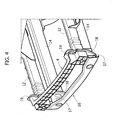
- the front module includes a bottom cross-member element 4 having a ribbed structure made of a single piece of plastic and/or composite material, the ends of which are slotted at the front into the parts projecting at the top of the aforesaid auxiliary plates 19 and are moreover bolted to the longitudinal sub-cab member 12.
- the slotted coupling enables limitation of the moment transmitted to the cross-member element 4 due to the loads acting on the longitudinal member following upon impact.
- the main plates 18, where these face the auxiliary plates 19, have through openings 20 sufficiently wide as to prevent interference with parts fixed with respect to the cross-member element 4 or to the longitudinal members 12 during any relative movements in a vertical direction between the longitudinal members 12 and the longitudinal members 14.
- the function of the main plates 18 and of the auxiliary plates 19 is to distribute the forces applied by the front cross member 16 following upon front impact between the longitudinal members 14 of the frame and the longitudinal sub-cab members 12 of the body.
- the front module 3 is assembled by providing initially the two side supports 9 on the body of the motor vehicle.
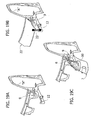
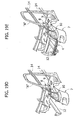
- one end of each support 9 is fixed to the upright "A" of the respective side of the body, as illustrated in Figure 19A so as to extend in cantilever fashion forwards starting from said upright.
- Figures 19A et seq. Show, for reasons of clarity, only part of the body of the motor vehicle.
- the bonnet 22 With the aid of a positioning tool 23 (illustrated schematically in Figure 19B ). In said condition, the entire body is subjected to a painting bath, after which further components of the front module are mounted.
- each side support 8 mounted on each side support 9 is the respective side support 8.
- each side support 8 has a front end with a resting surface 8a mounted on which is the respective frame 10 of the set of lights. The bottom part of said frame is left free to bend in order to prevent it from possibly constituting an obstacle to absorption of the energy of impact by means of collapse of the longitudinal member.
- a respective side support 10a is mounted on the support 8 and on the frame 10 and is then used in turn as rest for the respective side portion 7, which also rests on the respective longitudinal sub-cab member 12.
- the painted body and thus completed is mounted on the metal frame, which includes the two longitudinal members 14 ( Figure 19D ).
- the front module is completed with the bottom front cross-member element 4, which is fixed in the way that has been described with reference to Figures 4 and 5 and, on top of it, with the top front cross-member element 5 ( Figure 19E ).
- the central portion of the bumpers 6 is then mounted by being fixed underneath the bottom cross-member element 4.
- said element has at its bottom end a flexible tab 6a, which is joined to the longitudinal members 14 and is deformed in the course of the relative movements between the body, to which it is fixed with respect to the central bumper element 6, and the frame including the longitudinal members 14.
- the central bumper portion 6 has a front window 6b, which enables access to the front cross member 16 ( Figure 4 ), which has been described above.
- said arrangement enables an operator to rest his feet on the cross member 16 when he has to climb up to gain conveniently access to the top front part of the motor-vehicle in order to carry out maintenance operations.
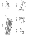
- the front grill which is not visible in Figure 3 , but is illustrated in itself in Figure 8 , and which is here designated by the reference number 21.
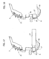
- Figure 18 illustrates a variant in which the central bumper portion 6 is mounted on the front cross member 16, in which case the front grill 21 has a bottom edge 21a that sets itself at the front and at a distance with respect to the top edge 6c of the central bumper portion 6, to enable relative displacements of said elements during the vertical movements of the body with respect to the frame.
- the front module 3 constituted only by elements made of plastic and/or composite material, is characterized by a very small number of components (fifteen in the example illustrated), for a considerable reduction of weight with respect to the solutions with front part made of sheet metal, and also enables a greater reliability of the structure as regards the relative movements between the body and the frame.
- the front module is devised also for facilitating the operations of assembly, with particular reference to the possibility of gaining access easily to the top front part of the motor vehicle.
- the parts made of plastic with hollow section can also advantageously be used for integrating therein pipes and service cables associated to the engine of the motor vehicle. The operations of assembly of the motor-vehicle are thus rationalized and simplified.
Landscapes
- Engineering & Computer Science (AREA)
- Chemical & Material Sciences (AREA)
- Combustion & Propulsion (AREA)
- Transportation (AREA)
- Mechanical Engineering (AREA)
- Body Structure For Vehicles (AREA)
- Motor Or Generator Frames (AREA)
Claims (13)
- Kraftfahrzeugstruktur, enthaltend:- einen Metallrahmen, der zwei Längselemente (14) enthält, die mit Querelementen (15) verbunden sind;- einen Metallkabinenkörper (2), der an dem Rahmen (14) angebracht ist und zwei Längsteilkabinenelemente (12) enthält, die an den Längselementen (14) des Rahmens mit Hilfe elastischer Halterungen (13) gehalten sind, die Relativbewegungen des Körpers (2) in einer vertikalen Richtung im Bezug auf den Rahmen (14) ermöglichen;- ein vorderes Metallquerelement (16) für die Absorption eines Aufpralls, das an den vorderen Enden der beiden Längselemente (14) des Rahmens befestigt ist;
dadurch gekennzeichnet, dass sie weiterhin enthält:- eine Metallfronthauptplatte (18), die mit dem vorderen Ende jedes Längsrahmenelementes (14) verbunden ist und einer entsprechenden Zusatzfrontmetallplatte (19) zugewandt ist, die mit dem vorderen Ende eines entsprechenden Längsteilkabinenelementes (12) verbunden ist, um die Kräfte zu verteilen, die durch das zuvor erwähnte vordere Querelement (16) zwischen den Längselementen des Rahmens (14) und den Längsteilkabinenelementen (12) wirken; und- eine Frontanordnung oder ein Frontmodul, die/das aus Elementen aufgebaut ist, die aus Kunststoff und/oder einem Kompositmaterial bestehen, und an dem Kabinenkörper (2) befestigt ist und den vorderen Teil der Karosserie des Kraftfahrzeugs bildet. - Kraftfahrzeugstruktur nach Anspruch 1, dadurch gekennzeichnet, dass das Frontmodul ein unteres vorderes Querelement (4) enthält, das aus einem einzigen Stück aus Kunststoff und/oder einem Kompositmaterial besteht und dessen Enden an der Vorderseite mit den zuvor erwähnten Zusatzfrontplatten (19) verbunden sind.
- Kraftfahrzeugstruktur nach Anspruch 3, dadurch gekennzeichnet, dass die zuvor erwähnten Hauptfrontplatten (18) Öffnungen (18a) haben, durch die die Enden des zuvor Erwähnten unteren Querelementes (4) an den zuvor erwähnten Zusatzplatten (19) befestigt sind, wobei die Öffnungen eine ausreichende Breite haben, um eine Berührung infolge der vertikalen Bewegungen zwischen dem Kabinenkörper (2) und den Längsrahmenelementen (14) zu verhindern.
- Kraftfahrzeugstruktur nach Anspruch 2, dadurch gekennzeichnet, dass das Frontmodul darüber hinaus ein oberes vorderes Querelement (5) enthält, das an dem unteren vorderen Querelement (4) angebracht ist.
- Kraftfahrzeugstruktur nach Anspruch 2, dadurch gekennzeichnet, dass das Frontmodul einen zentralen Stoßstangenabschnitt (6) enthält, der aus Kunststoff und/oder einem Kompositmaterial besteht und unter dem unteren Querelement (4) befestigt ist.
- Kraftfahrzeugstruktur nach Anspruch 1, dadurch gekennzeichnet, dass das Frontmodul zwei Seitenabschnitte (7) enthält, die jeweils einen Frontstoßstangen-Endabschnitt (7a) und einen Frontseitenabschnitt der Karosserie des Kraftfahrzeuges (7b) definieren.
- Kraftfahrzeugstruktur nach Anspruch 6, dadurch gekennzeichnet, dass jeder der Seitenabschnitte (7) an der Hinterseite mittels wenigstens einer Halterung (8, 9, 10a) durch die Säulen "A" des Kabinenkörpers des Kraftfahrzeugs gehalten ist.
- Kraftfahrzeugstruktur nach Anspruch 7, dadurch gekennzeichnet, dass die Halterungen eine untere Halterung (9), die kragarmartig an der Säule "A" der Kabine befestigt ist, und eine obere Halterung (8) enthalten, die an der unteren Halterung (9) angebracht ist.
- Kraftfahrzeugstruktur nach Anspruch 8, dadurch gekennzeichnet, dass die obere Halterung (8) ein vorderes Ende (8a) für die Aufnahme eines Umfangsrahmens (10) aus Kunststoff für einen entsprechenden vorderen Scheinwerfersatz des Kraftfahrzeugs hat.
- Kraftfahrzeugstruktur nach Anspruch 9, dadurch gekennzeichnet, dass sie zwei Zusatzhalterungen (10a) enthält, die jeweils von einer entsprechenden oberen Halterung (8) und einem entsprechenden Rahmen für einen Scheinwerfersatz (10) gehalten sind, der seinerseits den jeweiligen Seitenabschnitt (7) des Frontmoduls (3) hält.
- Kraftfahrzeugstruktur nach Anspruch 10, dadurch gekennzeichnet, dass das Frontmodul darüber hinaus zwei Radkastenelemente (11) enthält.
- Verfahren zum Montieren einer Kraftfahrzeugstruktur nach einem der vorhergehenden Ansprüche, dadurch gekennzeichnet, dass der Kabinenkörper (2) lackiert wird, worauf das zuvor erwähnte Frontmodul mit Hilfe einer nachfolgenden Montage der Teile aus Kunststoff und/oder einem Kompositmaterial, aus denen es besteht, daran angebracht wird, wobei der Kabinenkörper mit dem Rahmen (14) des Kraftfahrzeuges in einem Zwischenschritt der Montagevorgänge der unterschiedlichen Bauteile gekoppelt wird, die das Frontmodul bilden.
- Verfahren nach Anspruch 12, dadurch gekennzeichnet, dass das Koppeln des Kabinenkörpers (2) mit dem Rahmen (14) des Kraftfahrzeugs ausgeführt wird, nachdem die zuvor erwähnten Seitenabschnitte (7) mit den entsprechenden Halteelementen (8, 9, 10a) angebracht wurden und bevor die zuvor erwähnten unteren und oberen vorderen Querelemente des zuvor erwähnten zentralen Stoßstangenabschnittes (6) und des zuvor erwähnten Frontgrills (21) angebracht werden.
Priority Applications (3)
| Application Number | Priority Date | Filing Date | Title |
|---|---|---|---|
| DE602008005907T DE602008005907D1 (de) | 2008-12-15 | 2008-12-15 | Kraftfahrzeugstruktur mit einem Frontend-Modul mit Bestandteilen aus Kunststoff und/oder Komposit- Material |
| AT08425793T ATE503676T1 (de) | 2008-12-15 | 2008-12-15 | Kraftfahrzeugstruktur mit einem frontend-modul mit bestandteilen aus kunststoff und/oder komposit- material |
| EP08425793A EP2196381B1 (de) | 2008-12-15 | 2008-12-15 | Kraftfahrzeugstruktur mit einem Frontend-Modul mit Bestandteilen aus Kunststoff und/oder Komposit- Material |
Applications Claiming Priority (1)
| Application Number | Priority Date | Filing Date | Title |
|---|---|---|---|
| EP08425793A EP2196381B1 (de) | 2008-12-15 | 2008-12-15 | Kraftfahrzeugstruktur mit einem Frontend-Modul mit Bestandteilen aus Kunststoff und/oder Komposit- Material |
Publications (2)
| Publication Number | Publication Date |
|---|---|
| EP2196381A1 EP2196381A1 (de) | 2010-06-16 |
| EP2196381B1 true EP2196381B1 (de) | 2011-03-30 |
Family
ID=40512600
Family Applications (1)
| Application Number | Title | Priority Date | Filing Date |
|---|---|---|---|
| EP08425793A Not-in-force EP2196381B1 (de) | 2008-12-15 | 2008-12-15 | Kraftfahrzeugstruktur mit einem Frontend-Modul mit Bestandteilen aus Kunststoff und/oder Komposit- Material |
Country Status (3)
| Country | Link |
|---|---|
| EP (1) | EP2196381B1 (de) |
| AT (1) | ATE503676T1 (de) |
| DE (1) | DE602008005907D1 (de) |
Cited By (1)
| Publication number | Priority date | Publication date | Assignee | Title |
|---|---|---|---|---|
| US10086785B2 (en) | 2016-08-26 | 2018-10-02 | Ford Global Technologies, Llc | Frontal shield system for enhanced vehicle compatibility performance |
Families Citing this family (2)
| Publication number | Priority date | Publication date | Assignee | Title |
|---|---|---|---|---|
| DE102009004154A1 (de) * | 2009-01-09 | 2010-07-15 | Man Nutzfahrzeuge Ag | Verfahren zum Aufbau eines Vorderwagens eines Lastkraftwagens mit Fahrerhaus und Vorderwagen eines Lastwagens |
| CN110316253A (zh) * | 2018-03-30 | 2019-10-11 | 比亚迪股份有限公司 | 前端模块主体及前端模块总成 |
Family Cites Families (4)
| Publication number | Priority date | Publication date | Assignee | Title |
|---|---|---|---|---|
| JPH08230724A (ja) * | 1995-03-01 | 1996-09-10 | Mitsubishi Motors Corp | トラック |
| JPH11165653A (ja) * | 1997-11-30 | 1999-06-22 | Isuzu Motors Ltd | フレーム付ボディ車のバンパ取付構造 |
| DE60207015T2 (de) * | 2001-07-31 | 2006-08-03 | Nissan Motor Co., Ltd., Yokohama | Vorbaustruktur für ein Kraftfahrzeug |
| JP4103834B2 (ja) * | 2004-04-06 | 2008-06-18 | 日産自動車株式会社 | 車体前部構造 |
-
2008
- 2008-12-15 DE DE602008005907T patent/DE602008005907D1/de active Active
- 2008-12-15 AT AT08425793T patent/ATE503676T1/de not_active IP Right Cessation
- 2008-12-15 EP EP08425793A patent/EP2196381B1/de not_active Not-in-force
Cited By (1)
| Publication number | Priority date | Publication date | Assignee | Title |
|---|---|---|---|---|
| US10086785B2 (en) | 2016-08-26 | 2018-10-02 | Ford Global Technologies, Llc | Frontal shield system for enhanced vehicle compatibility performance |
Also Published As
| Publication number | Publication date |
|---|---|
| ATE503676T1 (de) | 2011-04-15 |
| DE602008005907D1 (de) | 2011-05-12 |
| EP2196381A1 (de) | 2010-06-16 |
Similar Documents
| Publication | Publication Date | Title |
|---|---|---|
| US8348333B2 (en) | Motor-vehicle structure having a front module constituted by elements made of plastic and/or composite material | |
| US6485089B2 (en) | Car body assembling method and body structure of a vehicle | |
| US8814248B2 (en) | Motor vehicle body with reinforcing structure | |
| JP5262524B2 (ja) | 車体前部構造 | |
| CN103847808B (zh) | 制造具有模块化车身的汽车的方法 | |
| EP1353837B1 (de) | Modul-kraftfahrzeug und assemblageverfahren | |
| KR20050085946A (ko) | 다용도 차량을 위한 전방프레임부품 | |
| EP1022212B1 (de) | Verbesserte struktur eines fahrerhauses für frontlenker mittel-schwere und schwere lastkraftwagen | |
| JP7203540B2 (ja) | 吸収システムと空気力学的システムとを備えるフロントブロックを形成するモノブロック部品 | |
| CN109109979B (zh) | 车辆前部结构及车身模块结构 | |
| KR20120110134A (ko) | 서스펜션 서브 프레임 | |
| US11097788B2 (en) | Electric vehicle with segmented frame and auxiliary frame in lattice structure | |
| JP7517267B2 (ja) | 車両前部構造 | |
| CN103359174A (zh) | 一种铝合金全承载式车身 | |
| DE102015205258A1 (de) | Fahrzeugfrontkarosseriestruktur | |
| WO2013021246A1 (en) | Front structure for vehicle | |
| KR102792224B1 (ko) | 차량용 차체 | |
| CN116101377A (zh) | 车辆中部结构 | |
| US20180273097A1 (en) | Vehicle front structure | |
| JP5934534B2 (ja) | 車体構造 | |
| CA1185295A (en) | Impact energy absorbing structure for f-f type motor vehicle | |
| JP3848563B2 (ja) | 車両の車体前部構造 | |
| EP2196381A1 (de) | Kraftfahrzeugstruktur mit einem Frontend-Modul mit Bestandteilen aus Kunststoff und/oder Komposit- Material | |
| US8007038B2 (en) | Vehicle body of a motor vehicle with a side sill | |
| CN108275097B (zh) | 用于汽车的保险杠横梁以及具有这种保险杠横梁的汽车 |
Legal Events
| Date | Code | Title | Description |
|---|---|---|---|
| PUAI | Public reference made under article 153(3) epc to a published international application that has entered the european phase |
Free format text: ORIGINAL CODE: 0009012 |
|
| 17P | Request for examination filed |
Effective date: 20090806 |
|
| AK | Designated contracting states |
Kind code of ref document: A1 Designated state(s): AT BE BG CH CY CZ DE DK EE ES FI FR GB GR HR HU IE IS IT LI LT LU LV MC MT NL NO PL PT RO SE SI SK TR |
|
| AX | Request for extension of the european patent |
Extension state: AL BA MK RS |
|
| GRAP | Despatch of communication of intention to grant a patent |
Free format text: ORIGINAL CODE: EPIDOSNIGR1 |
|
| GRAS | Grant fee paid |
Free format text: ORIGINAL CODE: EPIDOSNIGR3 |
|
| AKX | Designation fees paid |
Designated state(s): AT BE BG CH CY CZ DE DK EE ES FI FR GB GR HR HU IE IS IT LI LT LU LV MC MT NL NO PL PT RO SE SI SK TR |
|
| GRAA | (expected) grant |
Free format text: ORIGINAL CODE: 0009210 |
|
| AK | Designated contracting states |
Kind code of ref document: B1 Designated state(s): AT BE BG CH CY CZ DE DK EE ES FI FR GB GR HR HU IE IS IT LI LT LU LV MC MT NL NO PL PT RO SE SI SK TR |
|
| REG | Reference to a national code |
Ref country code: GB Ref legal event code: FG4D |
|
| REG | Reference to a national code |
Ref country code: CH Ref legal event code: EP |
|
| REG | Reference to a national code |
Ref country code: IE Ref legal event code: FG4D |
|
| REF | Corresponds to: |
Ref document number: 602008005907 Country of ref document: DE Date of ref document: 20110512 Kind code of ref document: P |
|
| REG | Reference to a national code |
Ref country code: DE Ref legal event code: R096 Ref document number: 602008005907 Country of ref document: DE Effective date: 20110512 |
|
| REG | Reference to a national code |
Ref country code: NL Ref legal event code: VDEP Effective date: 20110330 |
|
| PG25 | Lapsed in a contracting state [announced via postgrant information from national office to epo] |
Ref country code: LV Free format text: LAPSE BECAUSE OF FAILURE TO SUBMIT A TRANSLATION OF THE DESCRIPTION OR TO PAY THE FEE WITHIN THE PRESCRIBED TIME-LIMIT Effective date: 20110330 Ref country code: LT Free format text: LAPSE BECAUSE OF FAILURE TO SUBMIT A TRANSLATION OF THE DESCRIPTION OR TO PAY THE FEE WITHIN THE PRESCRIBED TIME-LIMIT Effective date: 20110330 Ref country code: GR Free format text: LAPSE BECAUSE OF FAILURE TO SUBMIT A TRANSLATION OF THE DESCRIPTION OR TO PAY THE FEE WITHIN THE PRESCRIBED TIME-LIMIT Effective date: 20110701 Ref country code: HR Free format text: LAPSE BECAUSE OF FAILURE TO SUBMIT A TRANSLATION OF THE DESCRIPTION OR TO PAY THE FEE WITHIN THE PRESCRIBED TIME-LIMIT Effective date: 20110330 Ref country code: SE Free format text: LAPSE BECAUSE OF FAILURE TO SUBMIT A TRANSLATION OF THE DESCRIPTION OR TO PAY THE FEE WITHIN THE PRESCRIBED TIME-LIMIT Effective date: 20110330 |
|
| LTIE | Lt: invalidation of european patent or patent extension |
Effective date: 20110330 |
|
| PG25 | Lapsed in a contracting state [announced via postgrant information from national office to epo] |
Ref country code: AT Free format text: LAPSE BECAUSE OF FAILURE TO SUBMIT A TRANSLATION OF THE DESCRIPTION OR TO PAY THE FEE WITHIN THE PRESCRIBED TIME-LIMIT Effective date: 20110330 Ref country code: SI Free format text: LAPSE BECAUSE OF FAILURE TO SUBMIT A TRANSLATION OF THE DESCRIPTION OR TO PAY THE FEE WITHIN THE PRESCRIBED TIME-LIMIT Effective date: 20110330 Ref country code: CY Free format text: LAPSE BECAUSE OF FAILURE TO SUBMIT A TRANSLATION OF THE DESCRIPTION OR TO PAY THE FEE WITHIN THE PRESCRIBED TIME-LIMIT Effective date: 20110330 Ref country code: FI Free format text: LAPSE BECAUSE OF FAILURE TO SUBMIT A TRANSLATION OF THE DESCRIPTION OR TO PAY THE FEE WITHIN THE PRESCRIBED TIME-LIMIT Effective date: 20110330 Ref country code: NO Free format text: LAPSE BECAUSE OF FAILURE TO SUBMIT A TRANSLATION OF THE DESCRIPTION OR TO PAY THE FEE WITHIN THE PRESCRIBED TIME-LIMIT Effective date: 20110630 |
|
| PG25 | Lapsed in a contracting state [announced via postgrant information from national office to epo] |
Ref country code: BE Free format text: LAPSE BECAUSE OF FAILURE TO SUBMIT A TRANSLATION OF THE DESCRIPTION OR TO PAY THE FEE WITHIN THE PRESCRIBED TIME-LIMIT Effective date: 20110330 |
|
| PG25 | Lapsed in a contracting state [announced via postgrant information from national office to epo] |
Ref country code: PT Free format text: LAPSE BECAUSE OF FAILURE TO SUBMIT A TRANSLATION OF THE DESCRIPTION OR TO PAY THE FEE WITHIN THE PRESCRIBED TIME-LIMIT Effective date: 20110801 Ref country code: EE Free format text: LAPSE BECAUSE OF FAILURE TO SUBMIT A TRANSLATION OF THE DESCRIPTION OR TO PAY THE FEE WITHIN THE PRESCRIBED TIME-LIMIT Effective date: 20110330 |
|
| PG25 | Lapsed in a contracting state [announced via postgrant information from national office to epo] |
Ref country code: RO Free format text: LAPSE BECAUSE OF FAILURE TO SUBMIT A TRANSLATION OF THE DESCRIPTION OR TO PAY THE FEE WITHIN THE PRESCRIBED TIME-LIMIT Effective date: 20110330 Ref country code: ES Free format text: LAPSE BECAUSE OF FAILURE TO SUBMIT A TRANSLATION OF THE DESCRIPTION OR TO PAY THE FEE WITHIN THE PRESCRIBED TIME-LIMIT Effective date: 20110711 Ref country code: SK Free format text: LAPSE BECAUSE OF FAILURE TO SUBMIT A TRANSLATION OF THE DESCRIPTION OR TO PAY THE FEE WITHIN THE PRESCRIBED TIME-LIMIT Effective date: 20110330 Ref country code: CZ Free format text: LAPSE BECAUSE OF FAILURE TO SUBMIT A TRANSLATION OF THE DESCRIPTION OR TO PAY THE FEE WITHIN THE PRESCRIBED TIME-LIMIT Effective date: 20110330 Ref country code: IS Free format text: LAPSE BECAUSE OF FAILURE TO SUBMIT A TRANSLATION OF THE DESCRIPTION OR TO PAY THE FEE WITHIN THE PRESCRIBED TIME-LIMIT Effective date: 20110730 |
|
| PG25 | Lapsed in a contracting state [announced via postgrant information from national office to epo] |
Ref country code: NL Free format text: LAPSE BECAUSE OF FAILURE TO SUBMIT A TRANSLATION OF THE DESCRIPTION OR TO PAY THE FEE WITHIN THE PRESCRIBED TIME-LIMIT Effective date: 20110330 |
|
| PLBE | No opposition filed within time limit |
Free format text: ORIGINAL CODE: 0009261 |
|
| STAA | Information on the status of an ep patent application or granted ep patent |
Free format text: STATUS: NO OPPOSITION FILED WITHIN TIME LIMIT |
|
| PG25 | Lapsed in a contracting state [announced via postgrant information from national office to epo] |
Ref country code: PL Free format text: LAPSE BECAUSE OF FAILURE TO SUBMIT A TRANSLATION OF THE DESCRIPTION OR TO PAY THE FEE WITHIN THE PRESCRIBED TIME-LIMIT Effective date: 20110330 Ref country code: DK Free format text: LAPSE BECAUSE OF FAILURE TO SUBMIT A TRANSLATION OF THE DESCRIPTION OR TO PAY THE FEE WITHIN THE PRESCRIBED TIME-LIMIT Effective date: 20110330 |
|
| 26N | No opposition filed |
Effective date: 20120102 |
|
| REG | Reference to a national code |
Ref country code: DE Ref legal event code: R097 Ref document number: 602008005907 Country of ref document: DE Effective date: 20120102 |
|
| PG25 | Lapsed in a contracting state [announced via postgrant information from national office to epo] |
Ref country code: MC Free format text: LAPSE BECAUSE OF NON-PAYMENT OF DUE FEES Effective date: 20111231 |
|
| REG | Reference to a national code |
Ref country code: IE Ref legal event code: MM4A |
|
| PG25 | Lapsed in a contracting state [announced via postgrant information from national office to epo] |
Ref country code: IE Free format text: LAPSE BECAUSE OF NON-PAYMENT OF DUE FEES Effective date: 20111215 |
|
| PG25 | Lapsed in a contracting state [announced via postgrant information from national office to epo] |
Ref country code: MT Free format text: LAPSE BECAUSE OF FAILURE TO SUBMIT A TRANSLATION OF THE DESCRIPTION OR TO PAY THE FEE WITHIN THE PRESCRIBED TIME-LIMIT Effective date: 20110330 |
|
| PG25 | Lapsed in a contracting state [announced via postgrant information from national office to epo] |
Ref country code: LU Free format text: LAPSE BECAUSE OF NON-PAYMENT OF DUE FEES Effective date: 20111215 |
|
| PG25 | Lapsed in a contracting state [announced via postgrant information from national office to epo] |
Ref country code: BG Free format text: LAPSE BECAUSE OF FAILURE TO SUBMIT A TRANSLATION OF THE DESCRIPTION OR TO PAY THE FEE WITHIN THE PRESCRIBED TIME-LIMIT Effective date: 20110630 |
|
| REG | Reference to a national code |
Ref country code: CH Ref legal event code: PL |
|
| GBPC | Gb: european patent ceased through non-payment of renewal fee |
Effective date: 20121215 |
|
| PG25 | Lapsed in a contracting state [announced via postgrant information from national office to epo] |
Ref country code: TR Free format text: LAPSE BECAUSE OF FAILURE TO SUBMIT A TRANSLATION OF THE DESCRIPTION OR TO PAY THE FEE WITHIN THE PRESCRIBED TIME-LIMIT Effective date: 20110330 |
|
| PG25 | Lapsed in a contracting state [announced via postgrant information from national office to epo] |
Ref country code: LI Free format text: LAPSE BECAUSE OF NON-PAYMENT OF DUE FEES Effective date: 20121231 Ref country code: HU Free format text: LAPSE BECAUSE OF FAILURE TO SUBMIT A TRANSLATION OF THE DESCRIPTION OR TO PAY THE FEE WITHIN THE PRESCRIBED TIME-LIMIT Effective date: 20110330 Ref country code: CH Free format text: LAPSE BECAUSE OF NON-PAYMENT OF DUE FEES Effective date: 20121231 |
|
| PG25 | Lapsed in a contracting state [announced via postgrant information from national office to epo] |
Ref country code: GB Free format text: LAPSE BECAUSE OF NON-PAYMENT OF DUE FEES Effective date: 20121215 |
|
| PGFP | Annual fee paid to national office [announced via postgrant information from national office to epo] |
Ref country code: DE Payment date: 20131211 Year of fee payment: 6 |
|
| PGFP | Annual fee paid to national office [announced via postgrant information from national office to epo] |
Ref country code: IT Payment date: 20131209 Year of fee payment: 6 Ref country code: FR Payment date: 20131209 Year of fee payment: 6 |
|
| REG | Reference to a national code |
Ref country code: DE Ref legal event code: R119 Ref document number: 602008005907 Country of ref document: DE |
|
| REG | Reference to a national code |
Ref country code: FR Ref legal event code: ST Effective date: 20150831 |
|
| PG25 | Lapsed in a contracting state [announced via postgrant information from national office to epo] |
Ref country code: DE Free format text: LAPSE BECAUSE OF NON-PAYMENT OF DUE FEES Effective date: 20150701 |
|
| PG25 | Lapsed in a contracting state [announced via postgrant information from national office to epo] |
Ref country code: FR Free format text: LAPSE BECAUSE OF NON-PAYMENT OF DUE FEES Effective date: 20141231 |
|
| PG25 | Lapsed in a contracting state [announced via postgrant information from national office to epo] |
Ref country code: IT Free format text: LAPSE BECAUSE OF NON-PAYMENT OF DUE FEES Effective date: 20141215 |