EP2196388A1 - Appareil d'aide à la man uvre - Google Patents
Appareil d'aide à la man uvre Download PDFInfo
- Publication number
- EP2196388A1 EP2196388A1 EP09804827A EP09804827A EP2196388A1 EP 2196388 A1 EP2196388 A1 EP 2196388A1 EP 09804827 A EP09804827 A EP 09804827A EP 09804827 A EP09804827 A EP 09804827A EP 2196388 A1 EP2196388 A1 EP 2196388A1
- Authority
- EP
- European Patent Office
- Prior art keywords
- height
- referential
- image
- cameras
- bird
- Prior art date
- Legal status (The legal status is an assumption and is not a legal conclusion. Google has not performed a legal analysis and makes no representation as to the accuracy of the status listed.)
- Withdrawn
Links
Images


Classifications
-
- B—PERFORMING OPERATIONS; TRANSPORTING
- B63—SHIPS OR OTHER WATERBORNE VESSELS; RELATED EQUIPMENT
- B63B—SHIPS OR OTHER WATERBORNE VESSELS; EQUIPMENT FOR SHIPPING
- B63B49/00—Arrangements of nautical instruments or navigational aids
-
- G—PHYSICS
- G01—MEASURING; TESTING
- G01C—MEASURING DISTANCES, LEVELS OR BEARINGS; SURVEYING; NAVIGATION; GYROSCOPIC INSTRUMENTS; PHOTOGRAMMETRY OR VIDEOGRAMMETRY
- G01C21/00—Navigation; Navigational instruments not provided for in groups G01C1/00 - G01C19/00
- G01C21/20—Instruments for performing navigational calculations
- G01C21/203—Instruments for performing navigational calculations specially adapted for water-borne vessels
-
- G—PHYSICS
- G06—COMPUTING OR CALCULATING; COUNTING
- G06T—IMAGE DATA PROCESSING OR GENERATION, IN GENERAL
- G06T3/00—Geometric image transformations in the plane of the image
- G06T3/40—Scaling of whole images or parts thereof, e.g. expanding or contracting
- G06T3/4038—Image mosaicing, e.g. composing plane images from plane sub-images
-
- H—ELECTRICITY
- H04—ELECTRIC COMMUNICATION TECHNIQUE
- H04N—PICTORIAL COMMUNICATION, e.g. TELEVISION
- H04N7/00—Television systems
- H04N7/18—Closed-circuit television [CCTV] systems, i.e. systems in which the video signal is not broadcast
- H04N7/181—Closed-circuit television [CCTV] systems, i.e. systems in which the video signal is not broadcast for receiving images from a plurality of remote sources
-
- B—PERFORMING OPERATIONS; TRANSPORTING
- B63—SHIPS OR OTHER WATERBORNE VESSELS; RELATED EQUIPMENT
- B63H—MARINE PROPULSION OR STEERING
- B63H25/00—Steering; Slowing-down otherwise than by use of propulsive elements; Dynamic anchoring, i.e. positioning vessels by means of main or auxiliary propulsive elements
- B63H25/02—Initiating means for steering, for slowing down, otherwise than by use of propulsive elements, or for dynamic anchoring
- B63H2025/028—Initiating means for steering, for slowing down, otherwise than by use of propulsive elements, or for dynamic anchoring using remote control means, e.g. wireless control; Equipment or accessories therefor
Definitions
- the present invention relates to a maneuvering assisting apparatus. More specifically, the present invention relates to a maneuvering assisting apparatus which combines a plurality of bird's eye view images based on outputs from a plurality of cameras installed at an upper portion of a moving object with reference to a referential height, and outputs a combined image thus generated from a display.
- Patent Literature1 Japanese Patent Application Laid-open Number 2008-48345
- the background art is not based on the assumption that bird's eye view images of object scenes captured in a visual field spanning a moving object and an outside world are combined, and there is a limit to the quality of the combined image based on the bird's eye view images.
- a maneuvering assisting apparatus comprises: a plurality of cameras each of which is installed at a different position of an upper portion of a moving object so as to have a visual field spanning the moving object and an outside world; a combiner which combines a plurality of object scene images respectively outputted from the plurality of cameras with reference to a referential height; a displayer which performs display processing on a combined image created by the combiner; and a changer which change a magnitude of the referential height in response to a height changing instruction.
- the moving object has a width that decreases with an increase in height
- a multiplexer which multiplexes a graphic image of the moving object corresponding to a height larger than the referential height onto the combined image created by the combiner, and the displayer executes the displaying processing after the multiplexing processing by the multiplexer.
- the combiner includes a transformer which transforms the plurality of object scene images into a plurality of bird's eye view images corresponding to the referential height.
- a visual field of each of the plurality of cameras has a common visual field
- the combiner further includes a connector which connects the plurality of bird's eye view images transformed by the transformer so as to be overlapped at the common visual fields.
- a first detector which detects at least one of a moving velocity of the moving object and a magnitude of a rock of the moving object
- a first issuer which issues the height changing instruction with reference to a detection result by the first detector.
- the moving object is equivalent to a ship
- a visual field of each of the plurality of cameras spans a deck of the ship and a water surface
- the changer changes a magnitude of the referential height among a plurality of magnitudes including a magnitude corresponding to the deck and a magnitude corresponding to the water surface.
- a second detector which detects a height of a pier when the ship performs landing/leaving steering
- a second issuer which issues the height changing instruction with reference to a detection result by the second detector.
- a maneuvering assisting program product is a maneuvering assisting program product to be executed by a processor of a maneuvering assisting apparatus having a plurality of cameras each of which is installed at a different position of an upper portion of a moving object so as to have a visual field spanning the moving object and an outside world, and comprises: a combining step of combining a plurality of object scene images respectively outputted from the plurality of cameras with reference to a referential height; a displaying step of performing display processing on a combined image created by the combining step; and a changing step of changing a magnitude of the referential height in response to a height changing instruction.
- a maneuvering assisting method is a maneuvering assisting method to be executed by a maneuvering assisting apparatus having a plurality of cameras each of which is installed at a different position of an upper portion of a moving object so as to have a visual field spanning the moving object and an outside world, and comprises: a combining step of combining a plurality of object scene images respectively outputted from the plurality of cameras with reference to a referential height; a displaying step of performing display processing on a combined image created by the combining step; and a changing step of changing a magnitude of the referential height in response to a height changing instruction.
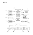
- a ship-maneuvering assisting apparatus 10 of this embodiment shown in Figure 1 includes four cameras C_1 to C_4.
- the cameras C_1 to C_4 output object scene images P_1 to P_4 in synchronization with a common timing signal at every 1/30 seconds, respectively.
- the outputted object scene images P_1 to P_4 are fetched by an image processing circuit 12.
- the ship-maneuvering assisting apparatus 10 is loaded in a ship 100 shown in Figure 2(A) and Figure 2(B) , and Figure 3(A) and Figure 3(B) .
- the ship 100 is configured by a ship hull 102, a cabin 104, and a navigation bridge 106.
- the cabin 104 is formed in a box shape at a substantially center of a top surface of the ship hull 102
- the navigation bridge 106 is formed in a box shape at a top-surface center of the cabin 104.
- a width of the cabin 104 is smaller than that of the top surface of the ship hull 102
- a width of the navigation bridge 106 is also smaller than that of the cabin 104.
- the ship 100 has a width that decreases with an increase in height.
- the camera C_1 is installed at an upper end center of an outer peripheral front surface of the navigation bridge 106, and the camera C_2 is installed at an upper end center of an outer peripheral right side surface of the navigation bridge 106. Moreover, the cameraC_3 is installed at an upper end center of an outer peripheral rear surface of the navigation bridge 106, and the cameraC_4 is installed at an upper end center of an outer peripheral left side surface of the navigation bridge 106.
- An optical axis of the camera C_1 extends obliquely downward forward of the navigation bridge 106, and an optical axis of the camera C_2 extends obliquely downward rightward of the ship 106.
- an optical axis of the camera C_3 extends obliquely downward rearward of navigation bridge 106, and an optical axis of the camera C_4 extends obliquely downward leftward of the ship 100.
- the camera C_1 has a visual field VW_1 capturing a front side of the navigation bridge 106
- the camera C_2 has a visual field VW_2 capturing a right side of the navigation bridge 106
- the camera C_3 has a visual field VW_3 capturing a rear side of the navigation bridge 106
- the camera C_4 has a visual field VW_4 capturing a left side of the navigation bridge 106.
- the visual fields VW_1 and VW_2 have a common visual field VW_12
- the visual fields VW_2 and VW_3 have a common visual field VW_23
- the visual fields VW_3 and VW_4 have a common visual field VW_34
- the visual fields VW_4 and VW_1 have a common visual field VW_41.
- the visual field VW_1 includes a front portion of a deck DCK1 and a water surface (sea surface) WS forward of the ship 100
- the visual field VW_2 includes a right portion of the deck DCK1 and the water surface WS rightward of the ship 100.
- the visual field VW_3 includes a rear portion of the deck DCK1 and the water surface WS rearward of the ship 100
- the visual field VW_4 includes a left portion of the deck DCK1 and the water surface WS leftward of the ship 100.
- a situation of the deck DCK1 and a situation of the water surface WS around the ship 100 is comprehended by the cameras C_1 to C_4.
- a CPU 12p arranged in the image processing circuit 12 produces a bird's eye view image BEV_1 shown in Figure 5(A) based on the object scene image P_1 outputted from the camera C_1, and produces a bird's eye view image BEV_2 shown in Figure 5(B) based on the object scene image P_2 outputted from the camera C_2.
- the CPU 12p further produces a bird's eye view image BEV_3 shown in Figure 5(C) based on the object scene image P_3 outputted from the camera C_3, and a bird's eye view image BEV_4 shown in Figure 5(D) based on the object scene image P_4 outputted from the camera C_4.
- the bird's eye view image BEV_1 is equivalent to an image captured by a virtual camera looking down on the visual field VW_1 in a perpendicular direction
- the bird's eye view image BEV_2 is equivalent to an image captured by a virtual camera looking down on the visual field VW_2 in a perpendicular direction
- the bird's eye view image BEV_3 is equivalent to an image captured by a virtual camera looking down on the visual field VW_3 in a perpendicular direction
- the bird's eye view image BEV_4 is equivalent to an image captured by a virtual camera looking down on the visual field VW_4 in a perpendicular direction.
- the bird's eye view image BEV_1 has a bird's eye view coordinate system X1 ⁇ Y1
- the bird's eye view image BEV_2 has a bird's eye view coordinate system X2 ⁇ Y2
- the bird's eye view image BEV_3 has a bird's eye view coordinate system X3 ⁇ Y3
- the bird's eye view image BEV_4 has a bird's eye view coordinate system X4 ⁇ Y4.
- a referential height designated by an operation with an operation panel 18 is refereed. That is, when the operation panel 18 is operated, a height changing instruction onto which a desired height is described is issued, and the CPU 12p creates each of the bird's eye view images BEV_1 to BEV_4 regarding the height described in the height changing instruction as a referential height.
- each of the visual fields VW_1 to VW4 includes an object which exists in heights different from one another, such as the deck DCK1 and the water surface WS.
- the bird's eye view images BEV_1 to BEV_4 are created based on an assumption that the surface of the deck DCK1 is an origin in the height direction (origin Ow described later).
- the bird's eye view images BEV_1 to BEV_4 are created based on an assumption that the water surface WS is an origin in the height direction.
- the bird's eye view images BEV_1 to BEV_4 thus created are held in a work area W1 of a memory 12m.
- the CPU 12p combines the bird's eye view images BEV_1 to BEV_4 with each other through a coordinate transformation.
- the bird's eye view images BEV_2 to BEV_4 are rotated and/or moved by using the bird's eye view image BEV_1 as a reference.
- a whole-circumference bird's eye view image shown in Figure 6 is obtained in a work area W2 of the memory 12m.
- an overlapping area OL_12 is equivalent to an area in which the common visual field VW_12 is reproduced
- an overlapping area OL_23 is equivalent to an area in which the common visual field VW_23 is reproduced
- an overlapping area OL_34 is equivalent to an area in which the common visual field VW_34 is reproduced
- an overlapping area OL_41 is equivalent to an area in which the common visual field VW_41 is reproduced.
- the CPU 12p multiplexes a graphic image G1 or G2 that imitates an upper portion of the ship 100 onto a center of the whole-circumference bird's eye view image on the work area W2, and cuts out one portion of an image in which the overlapping areas OL_12 to OL_41 are positioned at four corners.
- the cut-out image is applied to the display device 16 set in the navigation bridge 106 as a ship-maneuvering assisting image.
- the graphic image G1 is equivalent to an image that imitates the ship hull 102 (that is, the deck DCK1, the cabin 104 and the navigation bridge 106) from above. Furthermore, the graphic image G2 is equivalent to an image that imitates only the cabin 104 and the navigation bridge 106 from above.
- the graphic image G1 is selected when the referential height set by the operation panel 18 is lower than the height of the deck DCK1, and the graphic image G2 is selected when the referential height set by the operation panel 18 is equal to or higher than the height of the deck DCK1.
- the graphic image G1 is displayed at the center of the monitor screen, and actual images representing the pier LP and the water surface WS are displayed around the graphic image G1 (see Figure 8(A) to Figure 8(B) ).
- the actual image representing the pier LP is close to the graphic image G1 in accordance with the steering.
- the referential height during steering is conformed to the height of the pier LP, so that a displacement occurs at a combined section of the actual images representing the water surface WS.
- the graphic image G1 is updated by the graphic image G2, and actual images representing the deck DCK1, the pier LP and the water surface WS are displayed around the graphic image G2 (see Figure 8(C) to Figure 8(D) ).
- the referential height after landing is conformed to the height of the deck DCK1, so that displacements occur at a combined section of the actual images representing the pier LP and a combined section of the actual images representing the water surface WS.
- the bird's eye view images BEV_1 to BEV_4 are created according to the following procedure. It is noted that because each of the bird's eye view images BEV_1 to BEV_4 is created according to the same procedure, a procedure for creating the bird's eye view image BEV_3 is described as a representative example of the procedure for creating the bird's eye view images BEV_1 to BEV_4.
- the camera C_3 is placed, obliquely downward rearward, at an upper end center of a rear surface of the navigation bridge 106. If an angle of depression of the camera C_3 is assumed as " ⁇ d", an angle ⁇ shown in Figure 8 is equivalent to "180 degrees- ⁇ d". Furthermore, the angle ⁇ is defined in a range of 90 degrees ⁇ 180 degrees.
- Figure 9 shows a relationship among a camera coordinate system X ⁇ Y ⁇ Z, a coordinate system Xp ⁇ Yp on an imaging surface S of the camera C_3, and a world coordinate system Xw ⁇ Yw ⁇ Zw.
- the camera coordinate system X ⁇ Y ⁇ Z is a three-dimensional coordinate system having an X axis, Y axis, and Z axis as coordinate axes.
- the coordinate system Xp ⁇ Yp is a two-dimensional coordinate system having an Xp axis and Yp axis as coordinate axes.
- the world coordinate system Xw ⁇ Yw ⁇ Zw is a three-dimensional coordinate system having an Xw axis, Yw axis, and Zw axis as coordinate axes.
- an optical center of the camera C3 is an origin O.
- the Z axis is defined in an optical axis direction
- the X axis is defined in a direction orthogonal to the Z axis and parallel to the ground
- the Y axis is defined in a direction orthogonal to the Z axis and X axis.
- a center of the imaging surface S is an origin.
- the Xp axis is defined in a lateral direction of the imaging surface S and the Yp axis is defined in a vertical direction of the imaging surface S.
- an intersecting point between a perpendicular line passing through the origin O of the camera coordinate system X ⁇ Y ⁇ Z and the referential height face is an origin Ow.
- the Yw axis is defined in a direction vertical to the referential height face
- the Xw axis is defined in a direction parallel to the X axis of the camera coordinate system X ⁇ Y ⁇ Z
- the Zw axis is defined in a direction orthogonal to the Xw axis and Yw axis.
- a distance from the Xw axis to the X axis is "h"
- an obtuse angle formed by the Zw axis and Z axis is equivalent to the above described angle ⁇ .
- Equation 3 shows a transformation equation for transformation between the coordinates (xp, yp) of the coordinate system Xp ⁇ Yp on the imaging surface S and the coordinates (xw, zw) of the two-dimensional ground coordinate system Xw ⁇ Zw.
- xp yp fxw hsin ⁇ ⁇ + zwcos ⁇ ⁇ hcos ⁇ ⁇ - zwsin ⁇ ⁇ ⁇ f hsin ⁇ ⁇ + zwcos ⁇ ⁇
- a bird's eye view coordinate system X3 ⁇ Y3 of coordinate system of the bird's eye view image BEV_3 shown in Figure 5(C) is defined.
- the bird's eye view coordinate system X3 ⁇ Y3 is a two-dimensional coordinate system having an X3 axis and Y3 axis as coordinate axes.
- coordinates in the bird's eye view coordinate system X3 ⁇ Y3 are written as (x3, y3)
- a position of each pixel forming the bird's eye view image BEV_3 is represented by coordinates (x3, y3).
- "x3" and "y3" respectively indicate an X3-axis component and a Y3-axis component in the bird's eye view coordinate system X3 ⁇ Y3.
- a projection from the two-dimensional coordinate system Xw ⁇ Zw that represents the referential height face onto the bird's eye view coordinate system X3 ⁇ Y3 is equivalent to a so-called parallel projection.
- a height of a virtual camera i.e., a height of a virtual view point
- Equation 4 a transformation equation for transformation between the coordinates (xw, zw) of the two-dimensional coordinate system Xw ⁇ Zw and the coordinates (x3, y3) of the bird's eye view coordinate system X3 ⁇ Y3 is represented by Equation 4 below.
- a height H of the virtual camera is previously determined.
- Equation 7 is equivalent to a transformation equation for transformation of the coordinates (xp, yp) of the coordinate system Xp ⁇ Yp on the imaging surface S into the coordinates (x3, y3) of the bird's eye view coordinate system X3 ⁇ Y3.
- the coordinates (xp, yp) of the coordinate system Xp ⁇ Yp on the imaging surface S represent the coordinates of the object scene image P_3 captured by the camera C_3. Therefore, the object scene image P_3 from the camera C_3 is transformed into the bird's eye view image BEV_3 by using Equation 7.
- the object scene image P_3 firstly undergoes an image process, such as a lens distortion correction, and is then transformed into the bird's eye view image BEV_3 using Equation 7.
- the CPU 12p specifically executes a plurality of tasks in parallel, including an image processing task shown in Figure 11 and 12 . It is noted that a control program corresponding to these tasks is stored in a flash memory 14 (see Figure 1 ).
- a step S1 the referential height is set to the height of the water surface WS, and the graphic image to be multiplexed is set to the "G1" in a step S3.
- the object scene images P_1 to P_4 are fetched from the cameras C_1 to C_4, respectively, and in a step S7, the bird's eye view images BEV_1 to BEV_4 are created on the basis of the fetched object scene images P_1 to P_4.
- the referential height designated in the step S 1 or in a step S 17 described later is referred.
- the created bird's eye view images BEV_1 to BEV_4 are secured in the work area W1.
- a step S9 the bird's eye view images BEV_1 to BEV_4 created in the step S7 are combined together to create a whole-circumference bird's eye view image, and the created whole-circumference bird's eye view image is secured in the work area W2.
- the graphic image selected in the step S 1 or in a step S21 described later is multiplexed onto the center of the whole-circumference bird's eye view image secured in the work area W2.
- a step S 13 a part of the whole-circumference bird's eye view image onto which the graphic image is multiplexed is cut out from the work area W2, and the cut-out image is outputted toward the display device 16 as a ship-maneuvering assisting image.
- a step S 15 it is determined whether or not a height changing instruction is issued, and if "NO”, the process returns to the step S5 as it is whereas if "YES", the referential height is changed according to the height changing instruction in a step S 17.
- a step S 19 it is determined whether or not the changed referential height is equal to or more than the height of the deck DCK1. If “NO”, the process returns to the step S5 as it is whereas if "YES", the graphic image to be multiplexed is changed to the "G2" in a step S21, and then, the process returns to the step S5.
- each of the cameras C_1 to C_4 is installed at a different position of the navigation bridge 106 so as to have the visual field spanning the deck DCK1 and the water surface WS.
- the CPU 12p combines the object scene images P_1 to P_4 respectively outputted from the cameras C_1 to C_4 together with reference to the referential height (S7, S9).
- the ship 100 has a width that decreases with an increase in height, and the CPU 12p multiplexes the graphic image (the graphic image of the ship 100) corresponding to the height larger than the referential height onto the whole-circumference bird's eye view image created by the combining processing (S3, S11, S21).
- the CPU 12p further outputs a part of the whole-circumference bird's eye view image onto which the graphic image is multiplexed to the display device 16 as a ship-maneuvering assisting image (S13).
- the CPU 12p changes the magnitude of the referential height in response to the height changing instruction (S 17).
- the cameras C_1 to C_4 are installed in the positions different from one another, when the quality of the combined image representing the object existing at the referential height is emphasized, the quality of the combined image representing the object existing at a height different from the referential height is decreased.
- the magnitude of the referential height is changed in response to the height changing instruction, so that the referential height is conformed to a notable plane where the object exists, to thereby avoid the deterioration in quality of the combined image representing the notable plane. That is, the magnitude of the referential height is made changeable, and whereby the quality of the combined image representing the object scene captured by the visual field spanning the deck DCK1 and the water surface WS is adoptively improved.
- the height changing instruction is issued according to an operation with the operation panel 18, and the referential height is changed according to the height changing instruction thus issued.
- a velocity sensor 20 for sensing a moving velocity of the ship 100 a rock sensor 22 for sensing a rock of the ship 100, a GPS device 24 for detecting a present location of the ship 100 and a database DB storing map information including the height may be added as shown in Figure 13 , and the height changing instruction may be additionally issued on the basis of the output from the velocity sensor 20, the rock sensor 22 or the GPS device 24.
- the CPU 12p further executes a switch controlling task as shown in Figure 14 .
- a step S31 it is determined whether the ship 100 is steering for landing or leaving on the basis of outputs from the GPS device 24 and the velocity sensor 20. If “NO” here, the process proceeds to a step S37 as it is whereas if "YES", the process proceeds to the step S37 through steps S33 to S35.
- the step S33 the height of the pier LP is detected on the basis of an output from the GPS device 24 and the map information stored in the database DB. Furthermore, in the step S35, the height changing instruction onto which the detected height of the pier LP is described is issued.
- step S37 it is determined whether or not the moving velocity of the ship 100 sensed by the velocity sensor 20 is a high (whether or not the moving velocity is above a reference).
- step S43 it is determined whether or not the rock of the ship 100 detected by the rock sensor 22 is large (whether or not the rock is above a reference).
- step S37 it is determined whether or not the current referential height is equivalent to the height of the water surface WS in a step S39. If “YES” here, the process returns to the step S31 as it is whereas if "NO", the height changing instruction onto which the height of the water surface WS is described is issued in a step S41, and the process returns to the step S31.
- step S43 it is determined whether or not the current referential height is equivalent to the height of the deck DCK1 in a step S45. If “YES” here, the process returns to the step S31 as it is whereas if "NO”, the height changing instruction onto which the height of the deck DCK1 is described is issued in a step S47, and the process returns to the step S31. Here, if “NO” in both of the steps S37 and S43, the process returns to the step S31.
- the graphic image G1 is multiplexed onto the center of the whole-circumference bird's eye view image created by taking the pier LP as a referential height. Furthermore, during moving at high speeds, the graphic image G1 is multiplexed onto the center of the whole-circumference bird's eye view image created by taking the water surface WS as a referential height. Furthermore, when rocks occurs during stopping or moving at low speeds, the graphic image G2 is multiplexed onto the center of the whole-circumference bird's eye view image created by taking the deck DCK1 as referential height. Thus, the maneuverability is improved.
- the cameras C_1 to C_4 are installed at the upper end center of the navigation bridge 106.
- a ship 200 shown in Figure 15(A) to Figure 15(B) is prepared, and the camera C_1 may be installed at a bow in an obliquely downward, the camera C_2 may be installed at a forward right of the navigation bridge 206 obliquely downward, the camera C_3 may be installed at a reward of the navigation bridge 206 obliquely downward, and the camera C_4 may be installed at a forward left of the navigation bridge 206 obliquely downward.
- the visual fields VW_1 to VW_4 range as in a manner shown in Figure 16 .
- a graphic image G1 or G2 which imitates the ship 100 is multiplexed onto a whole-circumference bird's eye view image.
- ambient surrounding information such as signs-of-fish information created by a fish detector 28 and water depth information sensed by a water depth sensor 30 are additionally fetched, and the image based on the fetched ambient surrounding information may be multiplexed onto the whole-circumference bird's eye view image.
- the CPU 12p additionally executes processing in steps S51 to S57 shown in Figure 18 in the image processing task.
- steps S51 to S57 shown in Figure 18 in the image processing task.
- signs-of-fish information is fetched from the fish detector 28, and a signs-of-fish image based on the fetched signs-of-fish information is multiplexed onto the whole-circumference bird's eye view image in the step S53.
- water depth information is fetched from the water depth sensor 30, and a character indicating the water depth is multiplexed onto the whole-circumference bird's eye view image in the step S57.
- the process proceeds to the step S13. Adding these processing enhances entertainment.
- the coordinate transformation for producing a bird's eye view image from a photographed image which is described in the embodiment, is generally called a perspective projection transformation.
- the bird's eye view image may also be optionally produced from the photographed image through a well-known planer projection transformation.
- planer projection transformation a homography matrix (coordinate transformation matrix) for transforming a coordinate value of each pixel on the photographed image into a coordinate value of each pixel on the bird's eye view image is evaluated at a stage of camera calibrating processing.
- a method of evaluating the homography matrix is well known.
- the photographed image may be transformed into the bird's eye view image based on the homography matrix. In either way, the photographed image is transformed into the bird's eye view image by projecting the photographed image on the bird's eye view image.
Landscapes
- Engineering & Computer Science (AREA)
- Radar, Positioning & Navigation (AREA)
- Remote Sensing (AREA)
- General Physics & Mathematics (AREA)
- Physics & Mathematics (AREA)
- Signal Processing (AREA)
- Theoretical Computer Science (AREA)
- Multimedia (AREA)
- Automation & Control Theory (AREA)
- Chemical & Material Sciences (AREA)
- Combustion & Propulsion (AREA)
- Mechanical Engineering (AREA)
- Ocean & Marine Engineering (AREA)
- Closed-Circuit Television Systems (AREA)
- Image Processing (AREA)
- Traffic Control Systems (AREA)
- Image Analysis (AREA)
Applications Claiming Priority (2)
| Application Number | Priority Date | Filing Date | Title |
|---|---|---|---|
| JP2008203735A JP2010041530A (ja) | 2008-08-07 | 2008-08-07 | 操縦支援装置 |
| PCT/JP2009/061677 WO2010016340A1 (fr) | 2008-08-07 | 2009-06-26 | Appareil d'aide à la manœuvre |
Publications (1)
| Publication Number | Publication Date |
|---|---|
| EP2196388A1 true EP2196388A1 (fr) | 2010-06-16 |
Family
ID=41663563
Family Applications (1)
| Application Number | Title | Priority Date | Filing Date |
|---|---|---|---|
| EP09804827A Withdrawn EP2196388A1 (fr) | 2008-08-07 | 2009-06-26 | Appareil d'aide à la man uvre |
Country Status (4)
| Country | Link |
|---|---|
| US (1) | US20100225761A1 (fr) |
| EP (1) | EP2196388A1 (fr) |
| JP (1) | JP2010041530A (fr) |
| WO (1) | WO2010016340A1 (fr) |
Cited By (2)
| Publication number | Priority date | Publication date | Assignee | Title |
|---|---|---|---|---|
| US20110279673A1 (en) * | 2007-11-28 | 2011-11-17 | Flir Systems, Inc. | Maritime controls systems and methods |
| EP3483830A1 (fr) * | 2017-11-13 | 2019-05-15 | Yamaha Hatsudoki Kabushiki Kaisha | Dispositif de génération d'image de vue à vol d'oiseau pour un navire et son procédé d'étalonnage |
Families Citing this family (18)
| Publication number | Priority date | Publication date | Assignee | Title |
|---|---|---|---|---|
| JP5687740B2 (ja) * | 2013-08-27 | 2015-03-18 | 株式会社新来島どっく | 自動車運搬船の操舵室構造 |
| JP6877815B2 (ja) * | 2014-10-17 | 2021-05-26 | 日本無線株式会社 | 画像生成装置 |
| US10157452B1 (en) | 2015-09-28 | 2018-12-18 | Amazon Technologies, Inc. | Image processing system for image rectification |
| EP3206184A1 (fr) | 2016-02-11 | 2017-08-16 | NXP USA, Inc. | Appareil, procédé et système de réglage des données de calibrage prédéfini pour la génération d'une vue en perspective |
| DK179246B1 (en) * | 2016-03-31 | 2018-03-05 | Ap Moeller Maersk As | Container ship |
| JP2019186869A (ja) * | 2018-04-17 | 2019-10-24 | 株式会社ザクティ | 船舶の撮影装置およびその校正方法 |
| EP4648403A3 (fr) | 2018-10-04 | 2026-01-28 | Seadronix Corp. | Dispositif et procédé de surveillance de port et de navire |
| WO2020075429A1 (fr) * | 2018-10-09 | 2020-04-16 | 古野電気株式会社 | Dispositif et procédé de surveillance d'environnement |
| JP7317531B2 (ja) * | 2019-03-14 | 2023-07-31 | ヤマハ発動機株式会社 | 船舶の撮影システムおよびそれを備えた船舶、ならびに船舶の撮影システムの較正方法 |
| JP7232089B2 (ja) * | 2019-03-19 | 2023-03-02 | ヤマハ発動機株式会社 | 船舶用の表示装置、船舶および船舶用の画像表示方法 |
| JP7257200B2 (ja) | 2019-03-19 | 2023-04-13 | ヤマハ発動機株式会社 | 船舶および操船支援装置 |
| JP7339002B2 (ja) * | 2019-03-19 | 2023-09-05 | ヤマハ発動機株式会社 | 船舶および船舶用撮像装置 |
| JP2020161886A (ja) * | 2019-03-25 | 2020-10-01 | 株式会社ザクティ | 船舶の周辺確認システム |
| KR102052013B1 (ko) * | 2019-06-12 | 2019-12-04 | 한국해양과학기술원 | 선박용 카메라 영상 합성 시스템 및 선박용 카메라 교정방법 |
| KR102428892B1 (ko) * | 2020-05-08 | 2022-08-04 | 주식회사 아비커스 | 선박 운항 지원 시스템 및 이를 포함하는 선박 |
| JP2022139986A (ja) * | 2021-03-12 | 2022-09-26 | パイオニア株式会社 | 情報処理装置、制御方法、プログラム及び記憶媒体 |
| KR102527496B1 (ko) * | 2022-11-04 | 2023-05-02 | 한국해양과학기술원 | 극지 운항 선박의 통합 상태 모니터링 시스템 및 방법 |
| WO2026010071A1 (fr) * | 2024-07-02 | 2026-01-08 | 주식회사 아비커스 | Procédé de détermination de positions d'installation de caméras sur un navire, et navire sur lequel des caméras sont installées par celui-ci |
Family Cites Families (10)
| Publication number | Priority date | Publication date | Assignee | Title |
|---|---|---|---|---|
| JPH0431098U (fr) * | 1990-07-09 | 1992-03-12 | ||
| JP3753681B2 (ja) * | 2000-07-19 | 2006-03-08 | 松下電器産業株式会社 | 監視システム |
| WO2002007443A1 (fr) * | 2000-07-19 | 2002-01-24 | Matsushita Electric Industrial Co., Ltd. | Systeme de controle |
| JP4214219B2 (ja) * | 2002-11-26 | 2009-01-28 | 独立行政法人海上技術安全研究所 | 離接岸用操船支援装置 |
| US20050031169A1 (en) * | 2003-08-09 | 2005-02-10 | Alan Shulman | Birds eye view virtual imaging for real time composited wide field of view |
| JP4596978B2 (ja) * | 2005-03-09 | 2010-12-15 | 三洋電機株式会社 | 運転支援システム |
| JP4709684B2 (ja) * | 2006-04-13 | 2011-06-22 | 隼馬 今津 | 相手船動静監視装置 |
| JP4248570B2 (ja) | 2006-08-21 | 2009-04-02 | 三洋電機株式会社 | 画像処理装置並びに視界支援装置及び方法 |
| JP2008187566A (ja) * | 2007-01-31 | 2008-08-14 | Sanyo Electric Co Ltd | カメラ校正装置及び方法並びに車両 |
| JP5057936B2 (ja) * | 2007-11-09 | 2012-10-24 | アルパイン株式会社 | 鳥瞰画像生成装置および方法 |
-
2008
- 2008-08-07 JP JP2008203735A patent/JP2010041530A/ja not_active Withdrawn
-
2009
- 2009-06-06 US US12/680,772 patent/US20100225761A1/en not_active Abandoned
- 2009-06-26 WO PCT/JP2009/061677 patent/WO2010016340A1/fr not_active Ceased
- 2009-06-26 EP EP09804827A patent/EP2196388A1/fr not_active Withdrawn
Non-Patent Citations (1)
| Title |
|---|
| See references of WO2010016340A1 * |
Cited By (4)
| Publication number | Priority date | Publication date | Assignee | Title |
|---|---|---|---|---|
| US20110279673A1 (en) * | 2007-11-28 | 2011-11-17 | Flir Systems, Inc. | Maritime controls systems and methods |
| WO2012087715A1 (fr) * | 2010-12-20 | 2012-06-28 | Flir Systems, Inc. | Systèmes et procédés de commande maritimes |
| EP3483830A1 (fr) * | 2017-11-13 | 2019-05-15 | Yamaha Hatsudoki Kabushiki Kaisha | Dispositif de génération d'image de vue à vol d'oiseau pour un navire et son procédé d'étalonnage |
| US11468596B2 (en) | 2017-11-13 | 2022-10-11 | Yamaha Hatsudoki Kabushiki Kaisha | Bird's-eye view image generating device for vessel, and calibration method of the same |
Also Published As
| Publication number | Publication date |
|---|---|
| WO2010016340A1 (fr) | 2010-02-11 |
| JP2010041530A (ja) | 2010-02-18 |
| US20100225761A1 (en) | 2010-09-09 |
Similar Documents
| Publication | Publication Date | Title |
|---|---|---|
| EP2196388A1 (fr) | Appareil d'aide à la man uvre | |
| EP2174834A2 (fr) | Appareil pour aider à manoeuvrer | |
| JP5120880B2 (ja) | 画像処理装置及び画像処理方法 | |
| EP2739050B1 (fr) | Système de surveillance d'environnement de véhicule | |
| US8295644B2 (en) | Birds eye view virtual imaging for real time composited wide field of view | |
| EP3142066B1 (fr) | Synthétiseur d'image pour un système de surveillance d'ambiance | |
| US20110001819A1 (en) | Image Processing Apparatus | |
| JP4596978B2 (ja) | 運転支援システム | |
| KR101752613B1 (ko) | 작업 기계의 주변 감시 장치 | |
| JP6099333B2 (ja) | 画像生成装置、画像表示システム、パラメータ取得装置、画像生成方法及びパラメータ取得方法 | |
| KR101859229B1 (ko) | 건설기계의 작업 가이드 정보 표시 장치 및 방법 | |
| JP2009151524A (ja) | 画像表示方法および画像表示装置 | |
| CN105453558B (zh) | 车辆周边监视装置 | |
| JP5178454B2 (ja) | 車両周囲監視装置及び車両周囲監視方法 | |
| US10721397B2 (en) | Image processing system using predefined stitching configurations | |
| JP2010250640A (ja) | 画像処理装置 | |
| JP2020150459A (ja) | 船舶の撮影システムおよびそれを備えた船舶、ならびに船舶の撮影システムの較正方法 | |
| US20100271481A1 (en) | Maneuver Assisting Apparatus | |
| EP3396620B1 (fr) | Dispositif de commande d'affichage et procédé de commande d'affichage | |
| JP5805574B2 (ja) | 作業機械用周辺監視装置 | |
| JP2011114536A (ja) | 車両周辺画像提供装置 | |
| CN115968485A (zh) | 用于在显示装置上显示车辆环境的方法、处理单元和车辆 | |
| JP7569261B2 (ja) | 遠隔制御システム | |
| JP7729544B2 (ja) | 俯瞰映像提示システム | |
| JP2023169512A (ja) | 監視システム、監視システムの制御方法およびプログラム |
Legal Events
| Date | Code | Title | Description |
|---|---|---|---|
| PUAI | Public reference made under article 153(3) epc to a published international application that has entered the european phase |
Free format text: ORIGINAL CODE: 0009012 |
|
| 17P | Request for examination filed |
Effective date: 20100326 |
|
| AK | Designated contracting states |
Kind code of ref document: A1 Designated state(s): AT BE BG CH CY CZ DE DK EE ES FI FR GB GR HR HU IE IS IT LI LT LU LV MC MK MT NL NO PL PT RO SE SI SK TR |
|
| AX | Request for extension of the european patent |
Extension state: AL BA RS |
|
| DAX | Request for extension of the european patent (deleted) | ||
| STAA | Information on the status of an ep patent application or granted ep patent |
Free format text: STATUS: THE APPLICATION HAS BEEN WITHDRAWN |
|
| 18W | Application withdrawn |
Effective date: 20120312 |