EP2196407A1 - Capsule et dispositif de préparation d'une boisson - Google Patents
Capsule et dispositif de préparation d'une boisson Download PDFInfo
- Publication number
- EP2196407A1 EP2196407A1 EP08105965A EP08105965A EP2196407A1 EP 2196407 A1 EP2196407 A1 EP 2196407A1 EP 08105965 A EP08105965 A EP 08105965A EP 08105965 A EP08105965 A EP 08105965A EP 2196407 A1 EP2196407 A1 EP 2196407A1
- Authority
- EP
- European Patent Office
- Prior art keywords
- capsule
- bellows
- chamber
- cavity
- capsule according
- Prior art date
- Legal status (The legal status is an assumption and is not a legal conclusion. Google has not performed a legal analysis and makes no representation as to the accuracy of the status listed.)
- Granted
Links
- 239000002775 capsule Substances 0.000 title claims abstract description 159
- 230000035515 penetration Effects 0.000 claims abstract description 30
- 239000000126 substance Substances 0.000 claims abstract description 10
- 235000013361 beverage Nutrition 0.000 claims abstract description 6
- 239000007788 liquid Substances 0.000 claims abstract description 6
- 238000002360 preparation method Methods 0.000 claims abstract description 6
- 239000002689 soil Substances 0.000 claims description 10
- 230000000149 penetrating effect Effects 0.000 claims description 5
- 230000001154 acute effect Effects 0.000 claims description 2
- 239000003795 chemical substances by application Substances 0.000 claims 1
- 238000000605 extraction Methods 0.000 description 11
- 230000008901 benefit Effects 0.000 description 10
- 238000013124 brewing process Methods 0.000 description 8
- 238000000034 method Methods 0.000 description 7
- 230000008569 process Effects 0.000 description 7
- 239000000463 material Substances 0.000 description 6
- 230000006835 compression Effects 0.000 description 4
- 238000007906 compression Methods 0.000 description 4
- 239000004033 plastic Substances 0.000 description 4
- 230000000694 effects Effects 0.000 description 3
- 239000000843 powder Substances 0.000 description 3
- 230000009471 action Effects 0.000 description 2
- 239000012530 fluid Substances 0.000 description 2
- 238000004519 manufacturing process Methods 0.000 description 2
- 238000007789 sealing Methods 0.000 description 2
- XLYOFNOQVPJJNP-UHFFFAOYSA-N water Substances O XLYOFNOQVPJJNP-UHFFFAOYSA-N 0.000 description 2
- 239000004743 Polypropylene Substances 0.000 description 1
- 241001122767 Theaceae Species 0.000 description 1
- XAGFODPZIPBFFR-UHFFFAOYSA-N aluminium Chemical compound [Al] XAGFODPZIPBFFR-UHFFFAOYSA-N 0.000 description 1
- 229910052782 aluminium Inorganic materials 0.000 description 1
- 238000010276 construction Methods 0.000 description 1
- 235000013399 edible fruits Nutrition 0.000 description 1
- 238000005516 engineering process Methods 0.000 description 1
- 238000001914 filtration Methods 0.000 description 1
- 230000006872 improvement Effects 0.000 description 1
- 230000000977 initiatory effect Effects 0.000 description 1
- 238000001746 injection moulding Methods 0.000 description 1
- 230000007246 mechanism Effects 0.000 description 1
- 239000007769 metal material Substances 0.000 description 1
- -1 polypropylene Polymers 0.000 description 1
- 229920001155 polypropylene Polymers 0.000 description 1
- 230000000750 progressive effect Effects 0.000 description 1
- 230000009467 reduction Effects 0.000 description 1
- 230000002441 reversible effect Effects 0.000 description 1
- 238000012216 screening Methods 0.000 description 1
- 238000007493 shaping process Methods 0.000 description 1
- 239000000243 solution Substances 0.000 description 1
Images





Classifications
-
- B—PERFORMING OPERATIONS; TRANSPORTING
- B65—CONVEYING; PACKING; STORING; HANDLING THIN OR FILAMENTARY MATERIAL
- B65D—CONTAINERS FOR STORAGE OR TRANSPORT OF ARTICLES OR MATERIALS, e.g. BAGS, BARRELS, BOTTLES, BOXES, CANS, CARTONS, CRATES, DRUMS, JARS, TANKS, HOPPERS, FORWARDING CONTAINERS; ACCESSORIES, CLOSURES, OR FITTINGS THEREFOR; PACKAGING ELEMENTS; PACKAGES
- B65D85/00—Containers, packaging elements or packages, specially adapted for particular articles or materials
- B65D85/70—Containers, packaging elements or packages, specially adapted for particular articles or materials for materials not otherwise provided for
- B65D85/804—Disposable containers or packages with contents which are mixed, infused or dissolved in situ, i.e. without having been previously removed from the package
-
- B—PERFORMING OPERATIONS; TRANSPORTING
- B65—CONVEYING; PACKING; STORING; HANDLING THIN OR FILAMENTARY MATERIAL
- B65D—CONTAINERS FOR STORAGE OR TRANSPORT OF ARTICLES OR MATERIALS, e.g. BAGS, BARRELS, BOTTLES, BOXES, CANS, CARTONS, CRATES, DRUMS, JARS, TANKS, HOPPERS, FORWARDING CONTAINERS; ACCESSORIES, CLOSURES, OR FITTINGS THEREFOR; PACKAGING ELEMENTS; PACKAGES
- B65D85/00—Containers, packaging elements or packages, specially adapted for particular articles or materials
- B65D85/70—Containers, packaging elements or packages, specially adapted for particular articles or materials for materials not otherwise provided for
- B65D85/804—Disposable containers or packages with contents which are mixed, infused or dissolved in situ, i.e. without having been previously removed from the package
- B65D85/8043—Packages adapted to allow liquid to pass through the contents
-
- A—HUMAN NECESSITIES
- A47—FURNITURE; DOMESTIC ARTICLES OR APPLIANCES; COFFEE MILLS; SPICE MILLS; SUCTION CLEANERS IN GENERAL
- A47J—KITCHEN EQUIPMENT; COFFEE MILLS; SPICE MILLS; APPARATUS FOR MAKING BEVERAGES
- A47J31/00—Apparatus for making beverages
- A47J31/24—Coffee-making apparatus in which hot water is passed through the filter under pressure, i.e. in which the coffee grounds are extracted under pressure
- A47J31/34—Coffee-making apparatus in which hot water is passed through the filter under pressure, i.e. in which the coffee grounds are extracted under pressure with hot water under liquid pressure
- A47J31/36—Coffee-making apparatus in which hot water is passed through the filter under pressure, i.e. in which the coffee grounds are extracted under pressure with hot water under liquid pressure with mechanical pressure-producing means
-
- A—HUMAN NECESSITIES
- A47—FURNITURE; DOMESTIC ARTICLES OR APPLIANCES; COFFEE MILLS; SPICE MILLS; SUCTION CLEANERS IN GENERAL
- A47J—KITCHEN EQUIPMENT; COFFEE MILLS; SPICE MILLS; APPARATUS FOR MAKING BEVERAGES
- A47J31/00—Apparatus for making beverages
- A47J31/24—Coffee-making apparatus in which hot water is passed through the filter under pressure, i.e. in which the coffee grounds are extracted under pressure
- A47J31/34—Coffee-making apparatus in which hot water is passed through the filter under pressure, i.e. in which the coffee grounds are extracted under pressure with hot water under liquid pressure
- A47J31/36—Coffee-making apparatus in which hot water is passed through the filter under pressure, i.e. in which the coffee grounds are extracted under pressure with hot water under liquid pressure with mechanical pressure-producing means
- A47J31/3604—Coffee-making apparatus in which hot water is passed through the filter under pressure, i.e. in which the coffee grounds are extracted under pressure with hot water under liquid pressure with mechanical pressure-producing means with a mechanism arranged to move the brewing chamber between loading, infusing and ejecting stations
- A47J31/3623—Cartridges being employed
- A47J31/3628—Perforating means therefor
-
- A—HUMAN NECESSITIES
- A47—FURNITURE; DOMESTIC ARTICLES OR APPLIANCES; COFFEE MILLS; SPICE MILLS; SUCTION CLEANERS IN GENERAL
- A47J—KITCHEN EQUIPMENT; COFFEE MILLS; SPICE MILLS; APPARATUS FOR MAKING BEVERAGES
- A47J31/00—Apparatus for making beverages
- A47J31/24—Coffee-making apparatus in which hot water is passed through the filter under pressure, i.e. in which the coffee grounds are extracted under pressure
- A47J31/34—Coffee-making apparatus in which hot water is passed through the filter under pressure, i.e. in which the coffee grounds are extracted under pressure with hot water under liquid pressure
- A47J31/36—Coffee-making apparatus in which hot water is passed through the filter under pressure, i.e. in which the coffee grounds are extracted under pressure with hot water under liquid pressure with mechanical pressure-producing means
- A47J31/3604—Coffee-making apparatus in which hot water is passed through the filter under pressure, i.e. in which the coffee grounds are extracted under pressure with hot water under liquid pressure with mechanical pressure-producing means with a mechanism arranged to move the brewing chamber between loading, infusing and ejecting stations
- A47J31/3623—Cartridges being employed
- A47J31/3633—Means to perform transfer from a loading position to an infusing position
-
- A—HUMAN NECESSITIES
- A47—FURNITURE; DOMESTIC ARTICLES OR APPLIANCES; COFFEE MILLS; SPICE MILLS; SUCTION CLEANERS IN GENERAL
- A47J—KITCHEN EQUIPMENT; COFFEE MILLS; SPICE MILLS; APPARATUS FOR MAKING BEVERAGES
- A47J31/00—Apparatus for making beverages
- A47J31/40—Beverage-making apparatus with dispensing means for adding a measured quantity of ingredients, e.g. coffee, water, sugar, cocoa, milk, tea
Definitions
- the invention relates to a capsule according to the preamble of claim 1.
- Such capsules are widely used today as portion packages for the preparation of, for example, coffee. The consumer no longer has to worry about the dosage of the correct amount of coffee and after the extraction process, the capsule and its contents can be disposed of.
- the coffee powder also remains packed in the closed chamber aroma-tight and is protected from moisture.
- Portion packages in the form of capsules have long been known and in use.
- the prior art includes, for example, capsules as described in US Pat EP 1 101 430 and EP 1 344 722 are shown. These capsules are characterized by a robust construction, making them expensive and not suitable for certain perforation and brewing processes.
- a genus comparable comparable capsule shows the WO 2008/087099 ,
- the capsule has a bottom with a circumferential, outwardly directed channel.
- the annular groove in plan view is arranged with respect to the bottom center at the outer edge of the soil.
- the approximately flat channel bottom forms a penetratable zone for penetration means through which the extraction fluid can be passed during the brewing process.
- a central, convexly outwardly arched and approximately circular in cross-section bottom portion is arranged, which can be turned by a force from the outside inwards. This process is abrupt and erratic.
- Such a capsule has several disadvantages.
- a capsule having the features in claim 1. Characterized in that the bottom in a rest position (ie, in the unloaded state) for setting a preferably defined deformation is at least partially bellows-shaped, various advantages can be achieved.
- the bottom of the capsule by mechanical force from the outside can be pressed inwards.
- the inventive design of the capsule for example, the Eindschreibiefe and Eindschreibform the soil can be varied depending on the application.
- the special design of the floor allows to use different stop elements, which are associated with a capsule holder. The range of application of the capsule can thus be extended considerably.
- the floor has more wall material in relation to the floor area. As a result, the sealing effect can be improved during the brewing process.
- the reduction in the volume of the interior area has further advantages for brewing quality since the dry matter (e.g., coffee powder) in the chamber of the capsule is first compressed (i.e., before an extraction medium is introduced).
- the bottom of the capsule is movable from inside to outside by the action of hydraulic force as a result of introducing a liquid into the chamber of the capsule. In this case, an increase in the chamber volume of the capsule would result.
- the capsule chamber volume can be varied virtually as desired.
- the bottom can be deformed elastically or plastically in the cold state.
- the Eind Wegvorgang after removal of the compressive force is no longer reversible, leaving a recess remains.
- a consumer thus recognizes if manipulations have been made to the capsule in an undesirable manner in the area of the soil.
- the capsule can therefore also have a warranty function.
- a bellows in the ground is not readily produced, whereby the product is relatively forgery-proof.
- the bellows may extend in the direction of the ground plane. Theoretically, it is also conceivable that the bellows can run obliquely or even perpendicular to the ground plane.
- the bellows-type configuration may be formed by wave-shaped wall sections. These wall sections can rotate or surround the center of the ground in a plan view of the ground. Basically, it is also conceivable that the bellows-like configuration is achieved by a different shape of the soil.
- the wave-shaped wall sections may have inwardly directed U-shaped grooves.
- Such U-shaped grooves have advantages in particular when using plastic for the capsule body. For example, unwanted cracks or breaks in the Eindgurvorgang can be avoided.
- At least two channels are provided, which are of annular design with respect to a plan view of the floor and which preferably lie with respect to the center of the floor on concentric circles.
- three or more such grooves are conceivable.
- capsules are also conceivable whose gutters do not surround the center of the soil in a circular shape.
- the grooves could have a rectangular shape in plan view.
- the capsule may alternatively have a U-shaped groove, which is designed spirally in plan view.
- this channel may have at least two, and preferably at least three spiral passages.
- an outwardly directed, U-shaped web wall portion may be arranged between two adjacent grooves.
- the bellows-like configuration would thus be formed by outwardly and inwardly directed U-shaped grooves, which can alternately alternate.
- the grooves and / or the web wall section arranged between the grooves can / can be arcuate in cross-section and preferably approximately circular. This shaping of the bellows practically precludes unwanted damage to the soil during the pushing-in process.
- an outwardly directed, preferably approximately U-shaped, cross-section pin is provided for predetermining a stop surface for a die assigned to a device.
- the device may be a device for the preparation of a beverage and in particular of coffee, wherein the punch may be arranged in the region of a cavity of a capsule holder for the capsule.
- the pin has a lying on a ground plane, preferably extending approximately plane-parallel to the ground plane bottom portion. Handling advantages may result if the bottom section and at least the web wall section form an outline which lies on the ground plane.
- the bellows-like configuration of the floor may be formed by a bellows.
- a bellows may have in cross-section through the bottom a waveform that is alternately formed by outwardly and inwardly directed V-shaped grooves.
- the bellows has at least one pair of pleats with two flank walls connected in the direction of the cover (or inwardly) and at a preferably acute angle, which can form an inner fold line running around the center of the floor.
- This angle can advantageously be between 60 and 90 ° and more preferably about 80 °.
- the flank walls meet at an obtuse angle.
- acute-angled pairs of folds have the advantage that they allow a wide expansion of the bottom inwards during the pushing-in process.
- the flank walls do not have to taper towards each other so sharply that a sharp edge is formed in the region of the fold lines. It is advantageous in terms of manufacturing technology and also for perfect function if there is a rounding off in the area of the fold lines.
- the bellows may be configured spirally in plan view with respect to the bottom center. He may have at least two and preferably at least three spiral turns. However, the bellows can also have a plurality of pairs of folds whose fold lines can lie on concentric circles. However, it would also be conceivable for the crease lines in the case of cuboid or trapezoidal-shaped capsules to form rectangles in plan view, which are preferably arranged concentrically with one another in the bottom of the capsule.
- the bellows is curved at least slightly concave toward the inside or convexly outward or curved in the rest position.
- the spiral pairs of fold lines or fold lines formed in plan view would form a helical shape.
- Such a bulbous one Bellows bottom has the advantage that the Eind Wegvorgang can be facilitated.
- the side wall of the capsule could have a bellows-like configuration.
- Such a capsule could be advantageous for certain applications.
- the side wall could be formed at least by a bellows.
- a device for the preparation of a beverage using the previously described capsule has two chamber parts which can be pressed against each other to form an extraction chamber.
- a chamber part is designed as a capsule holder with a cavity for receiving the capsule and the other chamber part as a closing part for closing the cavity.
- the bottom of the cavity has means preferably containing a plurality of perforation elements for penetrating the bottom of the capsule.
- the closure member is also provided with one or more penetration elements for penetrating the lid. The mutually opposite penetration elements are configured such that when the cavity is closed, a capsule arranged therein can be penetrated at the bottom and on the lid for the passage of a liquid.
- a preferred embodiment of the device can be configured such that the penetration elements associated with the cavity can attack or penetrate the ground in the area of the bellows-like portion of the floor.
- the penetration elements can attack the ground in the area of the wave-shaped wall sections or in the region of the bellows.
- the penetration elements associated with the cavity can preferably be arranged uniformly distributed on a circle lying on the bottom of the cavity.
- the floor may have a punch designed as a central elevation around which the penetration elements can be arranged.
- the elevation may be cylindrical or frustoconical. It can also have a preferably plane-parallel to the bottom plane extending top, which can form a stop for a corresponding pin of the capsule.
- a helical compression spring can be arranged, the free end of which can be applied to the bottom of a capsule which can be pressed against the bottom of the cavity.
- the penetration elements may be pointed or tapered bodies. This body can have side surfaces provided with filter openings, wherein the filter openings can form a perforated screen configuration for optimum outflow of coffee extract.
- Such penetration elements are for example from the WO 2008/087099 or the WO 2008/023057 known.
- the stamp is detachably fastened to the bottom of the cavity of the capsule holder.
- the punch may for example have a bore through which a fastening screw for fixing the punch in the closure part can be carried out.
- Such an arrangement has the advantage that the device can be equipped in a simple manner as required with differently shaped and / or high punches.
- FIG. 1 shows a device 24 for brewing coffee with an inserted, designated 1 capsule.
- the capsule 1 has a capsule body 2, the bottom 4 of which is designed like a bellows.
- the structure and the function and operation of the provided with a bellows 11 capsule 1 will be described below with reference to the FIGS. 4 to 6 and especially on the basis of FIGS. 7 to 12 described in detail.
- the device 24 has two chamber parts 16 and 17, which are displaceable in the axial direction relative to each other.
- the chamber part 17 designed as a closure part is movable, while the other chamber part 16 is arranged fixedly in the device 24.
- the chamber part 16 is designed as a capsule receptacle with a cavity 26 into which the capsule 1 can be received.
- the capsule 1 between the capsule holder 16 and the closure member 17 is positioned.
- Both capsule holder 16 and closure member 17 each have penetration elements 18 and 19, respectively, with which the bottom of the capsule or a lid 5 of the capsule can be penetrated and through which an extraction medium can be passed.
- FIG. 1 shown initial position (open position)
- the capsule 1 shown penetration element are from the WO 2008/023057 become known and described in detail there. Basically, the capsule 1 is also suitable for other variants of penetration elements.
- the closing movement is effected manually by actuating a pivoting lever 23.
- the device 24 is exemplarily installed in a horizontal orientation in a corresponding machine. Also in the FIGS. 1 to 3 Locking mechanism shown is merely an example and does not limit the scope of protection.
- FIG. 2 shows the device in a closed position. How out FIG. 1 As can be seen, the bottom 4 of the capsule 1 was pressed inwards. The penetration elements 18 penetrate partially into the ground 4 in this position. A complete penetration of the bottom 4 results only in the brewing position in which the bottom 4 of the capsule abuts the bottom of the cavity of the capsule holder 16 as a result of the pressure build-up in the capsule chamber. This position is in FIG. 3 shown.
- FIGS. 4 to 6 show detailed representations of the capsule 1 in different positions.
- FIG. 4 shows the unloaded capsule 1 (capsule at rest, device in the open position);
- FIG. 5 shows the capsule 1 after the closing process, but before the application of a Brühdrucks; and
- FIG. 6 shows the capsule 1 in the extraction position ( FIG. 6 ).
- FIG. 4 For example, it can be clearly seen that the capsule 1 is positioned between the chamber parts 16 and 17 with the aid of a positioning unit (not described in greater detail).
- the chamber part 16 designed as a capsule holder has a cavity 26 for receiving the capsule. After the closing process, the capsule 1 is received in the cavity 26 of the capsule holder 16.
- the injection-side penetration elements 19 completely penetrate the film-like cover 5 in this position.
- the bottom 4 of the capsule 1 has a designated bellows 11, whereby it is achieved an advantageous floor flexibility.
- the bottom 4 of the capsule After initiating an extraction fluid into the capsule 1, the bottom 4 of the capsule is moved against the bottom of the cavity of the chamber part. After exceeding a certain Pressure in the capsule, the bottom 4 is positively and pressure-tight pressed against the bottom of the cavity. In this brewing or extraction position, the maximum outflow cross section at the filter openings 28 of the penetration elements 18 is reached.
- the extract then flows through drainage channels, where it can be suitably collected and channeled away (in FIG. 3 indicated by an arrow).
- Taste samples have surprisingly shown that excellent results can be achieved with such capsules over conventional capsules.
- FIGS. 5 and 6 Then a countersunk screw 32 can be seen, with which the punch 22 in the capsule holder 16 can be installed.
- the punch 22 can be dismantled in a simple manner and - if desired - replaced by another or replaced (see the following Fig. 5a and 6a ).
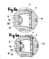
- FIGS. 5a and 6a shown device for brewing coffee or other drinks differs from the previous embodiment only by a differently designed stamp 22 (for the sake of simplicity without fastening screw shown). Also, the same capsule 1 is used here.
- the punch 22 is designed as a frusto-conical elevation, wherein the height of the punch 22 in the direction of the longitudinal center axis relative to the embodiment according to Figure 5/6 is significantly larger.
- the advantages of the capsule floor are mainly in FIG. 5a good to see. Thanks to the bellows 11, the bottom 4 of the capsule can be pressed relatively deep into the interior of the capsule. The chamber volume can thus be significantly reduced again.
- the side wall 3 of the capsule remains (more or less) unchanged.
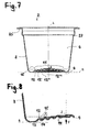
- the exact structural design of the bottom 4 of the capsule is from the FIGS. 7 and 8 recognizable.
- the designated 2 Capsule body for the capsule is designed as a one-piece molded part made of plastic and has a collar 25, the adjoining side wall 3 and the bottom 4.
- the capsule body 2 is rotationally symmetrical about a longitudinal central axis L and can be produced, for example, in a deep drawing process or in an injection molding process. It is preferably made of a plastic material such as polypropylene. Other materials or laminates are readily conceivable. Theoretically, it could even consist of a metallic material such as aluminum.
- the floor 4 is located on a level indicated by B floor level.
- a bellows 11 is arranged, which is formed by V-shaped grooves.
- the pleat pairs of the bellows 11 are denoted by 12, 12 ', 12 "and 12"' and surround the bottom center designated Z.
- the respective pairs of folds 12, 12 ', 12 "and 12"' may be arranged on concentric circles around the bottom center Z or, as in the present embodiment form a spiral.
- the helical configuration of the bellows 11 is particularly in FIG. 12 , but also in FIG. 11 good to see.
- FIG. 12 shows that the pairs of folds 12, 12 ', 12 "and 12"' merge into one another.
- Each pair of pleats 12 has two flank walls 13 and 14 which are directed inward or in the direction of the cover.
- the angle formed by the flank walls 13, 14 is designated by ⁇ , which in the present embodiment is approximately 80 °. It is advantageous if the flank walls 13, 14 taper towards each other, whereby a great flexibility of the soil is ensured. In the extreme case, the angle ⁇ could even be up to 169 °, but ranges between 60 ° and 120 ° have proved particularly advantageous in tests.
- FIG. 7 is then seen that the bellows 11 is slightly curved in the rest position inward.
- Such a concave configuration of the bottom has the advantage that the bellows can be pushed inwards simply by the action of force from the outside. This force is in FIG. 8 indicated by the arrow F.
- FIG. 9 shows a finished capsule 1 in a rest position, which can be used in a (not shown here) brewing device.
- the capsule 1 has a capsule body 2, which is closed in the region of the collar 25 aroma-tight by the lid 5.
- the cover 5, which preferably also consists of plastic material, is welded or glued to the capsule body.
- the substance 7 may be, for example, coffee powder or tea, wherein when flowing through the capsule with hot water, an extraction process takes place. In the case of the substance 7, however, it could also be, for example, a dry extract which completely passes into solution when flowing through with hot or cold water, so that no residues remain in the capsule at the end.
- a dry extract for the production of a fruit drink or a bouillon is on the one hand directly and without additional filter layer on the bottom 4 of the capsule 1; on the other hand, the filling 7 extends to the film-like lid. If the bellows 11 of the bottom 4 of the completely filled capsule 1 is pressed inwards, the substance 7 is compressed shortly before the actual brewing process when using the previously described device.
- the filtration during the brewing process is preferably carried out by penetrating into the capsule (not shown here) penetration elements. In principle, it would also be conceivable not to completely fill the chamber of the capsule with a substance and instead to allow a cavity.
- FIG. 10 two capsule body 2 can be seen, which are stacked on a stacking edge 27.
- the capsule bodies 2 can be easily and efficiently transported to a filling station. From the perspective representations of FIGS. 11 and 12 the spiral configuration of the bellows 11 can be seen.
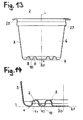
- FIGS. 13 to 18 show a capsule body 2 with an alternative embodiment of the bottom 4.
- the bottom 4 is partially configured bellows.
- the bellows-like configuration is formed by wave-shaped, the bottom center Z circumferential wall sections.
- the waveform has two inwardly directed U-shaped grooves 8 and 9. Between these two grooves 8.9 is also a U-shaped web wall portion 10 is arranged.
- the grooves 8 and 9 are configured approximately circular in cross section, wherein the groove radius R1 may be for example 2mm.
- the designated radius R2 of the likewise arcuate web wall portion 10 is also about 2mm.
- Centered in the bottom 4 is an outwardly directed, in cross-section approximately U-shaped pin for specifying a stop surface for the (not shown here) stamp the brewing device arranged. This pin interrupts the waveform of the adjacent bellows.
- the grooves 8 and 9 are configured annular in plan view of the bottom 4 and lie on concentric circles.
- the penetration means 31 consists of a flat disk on which a plurality of tent-like or pyramid-shaped penetration elements 18 are arranged in the form of a ring. These consist of hole side walls 29, which are inclined towards the penetration direction, wherein in each case one side wall can be punched out of the material of the disc and erected. The two remaining hole side walls are then placed and welded to the disc or with the erected hole side wall. In order to achieve an even easier penetration of the capsule base, additional knife edges 30 may be inserted. The hole side walls 29 may have very fine filter openings 28. The thus formed penetration body penetrate easily into the bellows of the capsule and cause a rapid outflow of the liquid with a very good screening effect.
Landscapes
- Engineering & Computer Science (AREA)
- Mechanical Engineering (AREA)
- Food Science & Technology (AREA)
- Apparatus For Making Beverages (AREA)
- Formation And Processing Of Food Products (AREA)
- Containers Having Bodies Formed In One Piece (AREA)
- Rigid Containers With Two Or More Constituent Elements (AREA)
- Packages (AREA)
Priority Applications (6)
| Application Number | Priority Date | Filing Date | Title |
|---|---|---|---|
| ES08105965.1T ES2436493T5 (es) | 2008-12-10 | 2008-12-10 | Cápsula y dispositivo para preparar una bebida |
| EP12194738.6A EP2565132B1 (fr) | 2008-12-10 | 2008-12-10 | Capsule, corps de capsule et dispositif de préparation d'une boisson |
| EP08105965.1A EP2196407B2 (fr) | 2008-12-10 | 2008-12-10 | Capsule et dispositif de préparation d'une boisson |
| KR1020117015161A KR20110092338A (ko) | 2008-12-10 | 2009-12-09 | 음료 조제용 캡슐 및 장치 |
| RU2011128320/12A RU2517011C2 (ru) | 2008-12-10 | 2009-12-09 | Контейнер и устройство для приготовления напитка |
| PCT/EP2009/066686 WO2010066766A2 (fr) | 2008-12-10 | 2009-12-09 | Capsule et dispositif pour préparer une boisson |
Applications Claiming Priority (1)
| Application Number | Priority Date | Filing Date | Title |
|---|---|---|---|
| EP08105965.1A EP2196407B2 (fr) | 2008-12-10 | 2008-12-10 | Capsule et dispositif de préparation d'une boisson |
Related Child Applications (3)
| Application Number | Title | Priority Date | Filing Date |
|---|---|---|---|
| EP12194738.6A Division EP2565132B1 (fr) | 2008-12-10 | 2008-12-10 | Capsule, corps de capsule et dispositif de préparation d'une boisson |
| EP12194738.6A Division-Into EP2565132B1 (fr) | 2008-12-10 | 2008-12-10 | Capsule, corps de capsule et dispositif de préparation d'une boisson |
| EP12194738.6 Division-Into | 2012-11-29 |
Publications (3)
| Publication Number | Publication Date |
|---|---|
| EP2196407A1 true EP2196407A1 (fr) | 2010-06-16 |
| EP2196407B1 EP2196407B1 (fr) | 2013-09-18 |
| EP2196407B2 EP2196407B2 (fr) | 2017-06-28 |
Family
ID=40688486
Family Applications (2)
| Application Number | Title | Priority Date | Filing Date |
|---|---|---|---|
| EP08105965.1A Active EP2196407B2 (fr) | 2008-12-10 | 2008-12-10 | Capsule et dispositif de préparation d'une boisson |
| EP12194738.6A Active EP2565132B1 (fr) | 2008-12-10 | 2008-12-10 | Capsule, corps de capsule et dispositif de préparation d'une boisson |
Family Applications After (1)
| Application Number | Title | Priority Date | Filing Date |
|---|---|---|---|
| EP12194738.6A Active EP2565132B1 (fr) | 2008-12-10 | 2008-12-10 | Capsule, corps de capsule et dispositif de préparation d'une boisson |
Country Status (5)
| Country | Link |
|---|---|
| EP (2) | EP2196407B2 (fr) |
| KR (1) | KR20110092338A (fr) |
| ES (1) | ES2436493T5 (fr) |
| RU (1) | RU2517011C2 (fr) |
| WO (1) | WO2010066766A2 (fr) |
Cited By (9)
| Publication number | Priority date | Publication date | Assignee | Title |
|---|---|---|---|---|
| WO2012011053A1 (fr) * | 2010-07-21 | 2012-01-26 | Capsa Sa | Capsule hermetique et systeme pour boisson extraite sous pression |
| ITBO20100677A1 (it) * | 2010-11-10 | 2012-05-11 | E T I S R L | Capsula per contenere un preparato per bevanda calda |
| WO2013105036A1 (fr) * | 2012-01-12 | 2013-07-18 | Sarong Societa' Per Azioni | Capsule pour boisson |
| ITTO20121125A1 (it) * | 2012-12-21 | 2014-06-22 | Lavazza Luigi Spa | Cartuccia per la preparazione di un prodotto liquido e procedimento per realizzarla |
| EP2904951A1 (fr) * | 2014-02-06 | 2015-08-12 | Luna Technology Systems LTS GmbH | Système de préparation d'un produit ébouillanté |
| US9840365B2 (en) | 2011-03-23 | 2017-12-12 | Kraft Foods R&D, Inc. | Capsule and a system for, and a method of, preparing a beverage |
| EP2575564B1 (fr) | 2010-05-28 | 2022-05-25 | Eugster/Frismag AG Elektrohaushaltgeräte | Dispositif et procédé d'infusion destiné à la lixiviation d'une dosette |
| EP4173995A4 (fr) * | 2021-05-10 | 2024-06-12 | Dongsuh Foods Corporation | Capsule déformable, procédé de préparation de boisson utilisant celle-ci, et système de préparation de boisson comprenant celle-ci |
| EP4585535A1 (fr) * | 2023-12-22 | 2025-07-16 | RPC Bramlage GmbH | Capsule pour la préparation d'une boisson |
Families Citing this family (11)
| Publication number | Priority date | Publication date | Assignee | Title |
|---|---|---|---|---|
| GB2480827B (en) * | 2010-06-01 | 2012-06-06 | Kraft Foods R & D Inc | Improvements in the preparation of beverages and liquid food products |
| EP2838815B1 (fr) * | 2012-04-11 | 2016-01-13 | Koninklijke Philips N.V. | Système de production de boisson et capsule |
| MX382567B (es) * | 2016-02-23 | 2025-03-13 | Gruppo Gimoka S R L | Capsula para producir bebidas. |
| MX2019011066A (es) * | 2017-03-17 | 2019-12-19 | Verbena 2017 B V | Capsula para preparar un producto de bebida. |
| US11504898B2 (en) | 2017-10-27 | 2022-11-22 | Kiefel Gmbh | Method of thermoforming a foil, forming tool, thermoforming tool, installation for thermoforming, container and brewing container |
| DE102018008119B4 (de) * | 2017-10-27 | 2019-06-06 | Kiefel Packaging B.V. | Aus einer folie thermogeformter behälter, verwendung eines verfahrens zum thermoformen einer folie, verwendung eines formwerkzeugs |
| DE102018008725A1 (de) * | 2018-09-18 | 2020-03-19 | Kiefel Packaging B.V. | Verfahren zum thermoformen einer folie, formwerkzeug oder thermoformwerkzeug |
| KR102273064B1 (ko) * | 2019-08-13 | 2021-07-05 | 윤재준 | 1회용 콜드브루 캡슐 |
| KR102353312B1 (ko) * | 2021-05-10 | 2022-01-20 | 동서식품주식회사 | 형상 변형 부재를 포함하는 음료 제조장치 및 이를 이용하여 음료를 제조하는 방법 |
| KR102571034B1 (ko) * | 2023-03-03 | 2023-08-24 | 김기철 | 헤어보조제를 수용하는 캡슐 및 두피브러시용 캡슐 |
| KR102610884B1 (ko) * | 2023-04-18 | 2023-12-06 | 동서식품주식회사 | 캡슐의 형상을 변형하기 위한 장치 및 이를 이용하여 캡슐의 형상을 변형하는 방법 |
Citations (9)
| Publication number | Priority date | Publication date | Assignee | Title |
|---|---|---|---|---|
| EP0242556A1 (fr) * | 1986-04-24 | 1987-10-28 | Societe Des Produits Nestle S.A. | Dispositif d'extraction de cartouches |
| US5327815A (en) * | 1991-07-05 | 1994-07-12 | Nestec S.A. | Device for use in beverage extraction machines |
| EP1101430A1 (fr) | 1999-11-16 | 2001-05-23 | Robert Hale | Système de filtration à cartouches |
| EP1344722A1 (fr) | 2002-03-14 | 2003-09-17 | René Schifferle | Cartouche mono-dose pour la préparation d'une boisson |
| US20060174769A1 (en) * | 2003-07-23 | 2006-08-10 | Eric Favre | Method for preparing a beverage from a capsule and device therefor |
| DE202005021174U1 (de) * | 2004-11-22 | 2007-06-21 | Caffita System S.P.A. | Getränkemaschine zur Herstellung eines Heißgetränks durch Aufbrühen und Extrahieren einer in einer Kapsel abgepackten Substanz |
| WO2007114685A1 (fr) * | 2006-02-17 | 2007-10-11 | Meccano Asia Ltd. | Paquetage et dispositif de preparation d'un produit alimentaire tel une boisson |
| WO2008023057A2 (fr) | 2006-08-25 | 2008-02-28 | Delica Ag | Moyen pour transpercer un emballage-portion comportant un élément d'extraction, dispositif d'extraction de l'élément d'extraction contenu dans l'emballage-portion et procédé de production dudit moyen |
| WO2008087099A2 (fr) | 2007-01-15 | 2008-07-24 | Swiss Caffe Asia Ltd. | Capsule, moyen de transpercement du fond de capsule et dispositif de préparation d'une boisson |
Family Cites Families (6)
| Publication number | Priority date | Publication date | Assignee | Title |
|---|---|---|---|---|
| EP0521188B1 (fr) * | 1991-07-05 | 1995-11-02 | Societe Des Produits Nestle S.A. | Dispositif permettant l'extraction de cartouches |
| ES2252113T3 (es) * | 2001-06-28 | 2006-05-16 | Societe Des Produits Nestle S.A. | Capsula flexible cerrada. |
| ES2292154T5 (es) † | 2004-10-25 | 2019-03-29 | Nestec Sa | Sistema de producción de bebidas |
| DE102004056224A1 (de) * | 2004-11-19 | 2006-05-24 | Tchibo Gmbh | System mit einer Kaffeemaschine und einer Portionskapsel |
| ITFI20060194A1 (it) * | 2006-08-04 | 2008-02-05 | Saeco Ipr Ltd | Dispositivo di infusione per la preparazione di bevande da capsule monodose |
| EP1975087B2 (fr) * | 2007-03-19 | 2018-05-16 | Nestec S.A. | Capsule avec technologie de régulation du débit |
-
2008
- 2008-12-10 EP EP08105965.1A patent/EP2196407B2/fr active Active
- 2008-12-10 EP EP12194738.6A patent/EP2565132B1/fr active Active
- 2008-12-10 ES ES08105965.1T patent/ES2436493T5/es active Active
-
2009
- 2009-12-09 RU RU2011128320/12A patent/RU2517011C2/ru active
- 2009-12-09 WO PCT/EP2009/066686 patent/WO2010066766A2/fr not_active Ceased
- 2009-12-09 KR KR1020117015161A patent/KR20110092338A/ko not_active Withdrawn
Patent Citations (9)
| Publication number | Priority date | Publication date | Assignee | Title |
|---|---|---|---|---|
| EP0242556A1 (fr) * | 1986-04-24 | 1987-10-28 | Societe Des Produits Nestle S.A. | Dispositif d'extraction de cartouches |
| US5327815A (en) * | 1991-07-05 | 1994-07-12 | Nestec S.A. | Device for use in beverage extraction machines |
| EP1101430A1 (fr) | 1999-11-16 | 2001-05-23 | Robert Hale | Système de filtration à cartouches |
| EP1344722A1 (fr) | 2002-03-14 | 2003-09-17 | René Schifferle | Cartouche mono-dose pour la préparation d'une boisson |
| US20060174769A1 (en) * | 2003-07-23 | 2006-08-10 | Eric Favre | Method for preparing a beverage from a capsule and device therefor |
| DE202005021174U1 (de) * | 2004-11-22 | 2007-06-21 | Caffita System S.P.A. | Getränkemaschine zur Herstellung eines Heißgetränks durch Aufbrühen und Extrahieren einer in einer Kapsel abgepackten Substanz |
| WO2007114685A1 (fr) * | 2006-02-17 | 2007-10-11 | Meccano Asia Ltd. | Paquetage et dispositif de preparation d'un produit alimentaire tel une boisson |
| WO2008023057A2 (fr) | 2006-08-25 | 2008-02-28 | Delica Ag | Moyen pour transpercer un emballage-portion comportant un élément d'extraction, dispositif d'extraction de l'élément d'extraction contenu dans l'emballage-portion et procédé de production dudit moyen |
| WO2008087099A2 (fr) | 2007-01-15 | 2008-07-24 | Swiss Caffe Asia Ltd. | Capsule, moyen de transpercement du fond de capsule et dispositif de préparation d'une boisson |
Cited By (22)
| Publication number | Priority date | Publication date | Assignee | Title |
|---|---|---|---|---|
| EP2575564B1 (fr) | 2010-05-28 | 2022-05-25 | Eugster/Frismag AG Elektrohaushaltgeräte | Dispositif et procédé d'infusion destiné à la lixiviation d'une dosette |
| AU2011281237B2 (en) * | 2010-07-21 | 2014-10-09 | Mocoffee Ag | Sealed capsule and system for a beverage extracted under pressure |
| FR2962893A1 (fr) * | 2010-07-21 | 2012-01-27 | Capsa Sa | Capsule hermetique pour boisson extraite sous pression |
| WO2012011053A1 (fr) * | 2010-07-21 | 2012-01-26 | Capsa Sa | Capsule hermetique et systeme pour boisson extraite sous pression |
| KR20130042573A (ko) * | 2010-07-21 | 2013-04-26 | 카프자 에스에이 | 압력 하에서 추출된 음료를 위한 밀봉된 캡슐 및 시스템 |
| EP2452893A1 (fr) * | 2010-11-10 | 2012-05-16 | E.T.I. S.r.l. | Capsule destinée à contenir une préparation pour boisson chaude |
| ITBO20100677A1 (it) * | 2010-11-10 | 2012-05-11 | E T I S R L | Capsula per contenere un preparato per bevanda calda |
| US9840365B2 (en) | 2011-03-23 | 2017-12-12 | Kraft Foods R&D, Inc. | Capsule and a system for, and a method of, preparing a beverage |
| WO2013105036A1 (fr) * | 2012-01-12 | 2013-07-18 | Sarong Societa' Per Azioni | Capsule pour boisson |
| US10150610B2 (en) | 2012-01-12 | 2018-12-11 | Sarong Societa' Per Azioni | Capsule for beverage |
| ITTO20121125A1 (it) * | 2012-12-21 | 2014-06-22 | Lavazza Luigi Spa | Cartuccia per la preparazione di un prodotto liquido e procedimento per realizzarla |
| WO2014097039A1 (fr) * | 2012-12-21 | 2014-06-26 | Luigi Lavazza S.P.A. | Cartouche de préparation d'un produit liquide et son procédé de production |
| RU2621958C2 (ru) * | 2012-12-21 | 2017-06-08 | Луиджи Лавацца С.П.А. | Картридж для приготовления жидкого продукта и способ его изготовления |
| WO2015117890A1 (fr) * | 2014-02-06 | 2015-08-13 | Luna Technology Systems Lts Gmbh | Système de préparation d'une infusion |
| JP2017507704A (ja) * | 2014-02-06 | 2017-03-23 | キュー・ビー・オー・コーヒー・ゲゼルシャフト・ミット・ベシュレンクテル・ハフツングQbo Coffee Gmbh | 醸造製品を準備するためのシステム |
| AU2015215125B2 (en) * | 2014-02-06 | 2018-03-29 | Qbo Coffee Gmbh | System for preparing a brewed product |
| CN106132255A (zh) * | 2014-02-06 | 2016-11-16 | Qbo咖啡有限责任公司 | 用于制备冲泡产品的系统 |
| RU2681599C2 (ru) * | 2014-02-06 | 2019-03-11 | Кбо Кофи ГмбХ | Система для приготовления заварного продукта |
| US10376089B2 (en) | 2014-02-06 | 2019-08-13 | Qbo Coffee Gmbh | System for preparing a brewed product |
| EP2904951A1 (fr) * | 2014-02-06 | 2015-08-12 | Luna Technology Systems LTS GmbH | Système de préparation d'un produit ébouillanté |
| EP4173995A4 (fr) * | 2021-05-10 | 2024-06-12 | Dongsuh Foods Corporation | Capsule déformable, procédé de préparation de boisson utilisant celle-ci, et système de préparation de boisson comprenant celle-ci |
| EP4585535A1 (fr) * | 2023-12-22 | 2025-07-16 | RPC Bramlage GmbH | Capsule pour la préparation d'une boisson |
Also Published As
| Publication number | Publication date |
|---|---|
| WO2010066766A2 (fr) | 2010-06-17 |
| EP2196407B1 (fr) | 2013-09-18 |
| RU2011128320A (ru) | 2013-01-20 |
| WO2010066766A3 (fr) | 2010-08-05 |
| EP2565132B1 (fr) | 2015-10-28 |
| KR20110092338A (ko) | 2011-08-17 |
| EP2196407B2 (fr) | 2017-06-28 |
| ES2436493T5 (es) | 2017-11-08 |
| RU2517011C2 (ru) | 2014-05-27 |
| EP2565132A1 (fr) | 2013-03-06 |
| ES2436493T3 (es) | 2014-01-02 |
Similar Documents
| Publication | Publication Date | Title |
|---|---|---|
| EP2196407B1 (fr) | Capsule et dispositif de préparation d'une boisson | |
| EP2053950B1 (fr) | Moyen pour transpercer un emballage-portion comportant un élément d'extraction, dispositif d'extraction de l'élément d'extraction contenu dans l'emballage-portion et procédé de production dudit moyen | |
| EP1944248B1 (fr) | Capsule, moyen de pénétration du fond d'une capsule et dispositif de préparation d'une boisson | |
| DE102009007553B4 (de) | Kapsel für die Zubereitung einer Flüssigkeit, insbesondere eines Kaffeegetränks | |
| DE4192762C2 (de) | Apparat und Kapsel zur Herstellung eines flüssigen Produktes | |
| DE602004001387T2 (de) | Kartusche für Kaffee | |
| EP3052407B1 (fr) | Capsule et système de préparation d'un produit alimentaire liquide | |
| CH711083A2 (de) | Kapsel, System zur Zubereitung eines Getränks aus einer solchen Kapsel und Verwendung einer solchen Kapsel in einer Getränkezubereitungsvorrichtung. | |
| DE202015100813U1 (de) | Dichtung für Kaffeekapseln | |
| EP3924271B1 (fr) | Système servant à préparer une boisson à partir d'une capsule | |
| CH709273A2 (de) | Kapsel umfassend einen vorzugsweise rotationssymmetrisch ausgebildeten Kapselkörper. | |
| EP3322651B1 (fr) | Élément filtrant comprenant un évidement | |
| CH709785A2 (de) | Kapsel für Getränkzubereitung. | |
| DE602005002186T2 (de) | Kapsel, Vorrichtung und Verfahren zur Herstellung von Kaffee oder eines anderen Getränks | |
| EP3118139B1 (fr) | Système et capsule comprenant un corps de capsule de preference a rotation symetrique | |
| EP4255826B1 (fr) | Capsule-dosette pour préparer une boisson dans une machine de préparation de boisson, système pour préparer une boisson et procédé et installation pour produire une capsule-dosette | |
| EP3310693B1 (fr) | Capsule pour la production des boissons | |
| DE602005001476T2 (de) | Verschlussvorrichtung mit einer Kammer für einen Behälter zur getrennten Aufbewahrung von Substanzen vor dem Gebrauch | |
| DE2449516C3 (de) | Flaschenverschluß mit einem Ausgießkörper | |
| DE102015102416A1 (de) | Dichtung für Kaffeekapseln | |
| CH712563A1 (de) | Kapsel für die Herstellung eines Getränks. | |
| EP3166872B1 (fr) | Capsule avec un corps de symetrie rotational | |
| DE20108328U1 (de) | Sprühdose | |
| DE102005058362B4 (de) | Aggregat aus Filterbehälter und Filtereinsatz | |
| EP3686127A1 (fr) | Capsule destinée à la préparation d'une boisson |
Legal Events
| Date | Code | Title | Description |
|---|---|---|---|
| PUAI | Public reference made under article 153(3) epc to a published international application that has entered the european phase |
Free format text: ORIGINAL CODE: 0009012 |
|
| AK | Designated contracting states |
Kind code of ref document: A1 Designated state(s): AT BE BG CH CY CZ DE DK EE ES FI FR GB GR HR HU IE IS IT LI LT LU LV MC MT NL NO PL PT RO SE SI SK TR |
|
| AX | Request for extension of the european patent |
Extension state: AL BA MK RS |
|
| 17P | Request for examination filed |
Effective date: 20101117 |
|
| 17Q | First examination report despatched |
Effective date: 20101230 |
|
| AKX | Designation fees paid |
Designated state(s): AT BE BG CH CY CZ DE DK EE ES FI FR GB GR HR HU IE IS IT LI LT LU LV MC MT NL NO PL PT RO SE SI SK TR |
|
| GRAP | Despatch of communication of intention to grant a patent |
Free format text: ORIGINAL CODE: EPIDOSNIGR1 |
|
| RIN1 | Information on inventor provided before grant (corrected) |
Inventor name: DEUBER, LOUIS |
|
| GRAS | Grant fee paid |
Free format text: ORIGINAL CODE: EPIDOSNIGR3 |
|
| GRAA | (expected) grant |
Free format text: ORIGINAL CODE: 0009210 |
|
| AK | Designated contracting states |
Kind code of ref document: B1 Designated state(s): AT BE BG CH CY CZ DE DK EE ES FI FR GB GR HR HU IE IS IT LI LT LU LV MC MT NL NO PL PT RO SE SI SK TR |
|
| REG | Reference to a national code |
Ref country code: GB Ref legal event code: FG4D Free format text: NOT ENGLISH |
|
| REG | Reference to a national code |
Ref country code: CH Ref legal event code: EP |
|
| REG | Reference to a national code |
Ref country code: IE Ref legal event code: FG4D Free format text: LANGUAGE OF EP DOCUMENT: GERMAN |
|
| REG | Reference to a national code |
Ref country code: AT Ref legal event code: REF Ref document number: 632621 Country of ref document: AT Kind code of ref document: T Effective date: 20131015 |
|
| REG | Reference to a national code |
Ref country code: DE Ref legal event code: R096 Ref document number: 502008010677 Country of ref document: DE Effective date: 20131114 |
|
| REG | Reference to a national code |
Ref country code: CH Ref legal event code: NV Representative=s name: HEPP WENGER RYFFEL AG, CH |
|
| REG | Reference to a national code |
Ref country code: NL Ref legal event code: T3 |
|
| REG | Reference to a national code |
Ref country code: ES Ref legal event code: FG2A Ref document number: 2436493 Country of ref document: ES Kind code of ref document: T3 Effective date: 20140102 |
|
| PG25 | Lapsed in a contracting state [announced via postgrant information from national office to epo] |
Ref country code: NO Free format text: LAPSE BECAUSE OF FAILURE TO SUBMIT A TRANSLATION OF THE DESCRIPTION OR TO PAY THE FEE WITHIN THE PRESCRIBED TIME-LIMIT Effective date: 20131218 Ref country code: CY Free format text: LAPSE BECAUSE OF FAILURE TO SUBMIT A TRANSLATION OF THE DESCRIPTION OR TO PAY THE FEE WITHIN THE PRESCRIBED TIME-LIMIT Effective date: 20130828 Ref country code: SE Free format text: LAPSE BECAUSE OF FAILURE TO SUBMIT A TRANSLATION OF THE DESCRIPTION OR TO PAY THE FEE WITHIN THE PRESCRIBED TIME-LIMIT Effective date: 20130918 Ref country code: LT Free format text: LAPSE BECAUSE OF FAILURE TO SUBMIT A TRANSLATION OF THE DESCRIPTION OR TO PAY THE FEE WITHIN THE PRESCRIBED TIME-LIMIT Effective date: 20130918 Ref country code: HR Free format text: LAPSE BECAUSE OF FAILURE TO SUBMIT A TRANSLATION OF THE DESCRIPTION OR TO PAY THE FEE WITHIN THE PRESCRIBED TIME-LIMIT Effective date: 20130918 |
|
| PGFP | Annual fee paid to national office [announced via postgrant information from national office to epo] |
Ref country code: CZ Payment date: 20131209 Year of fee payment: 6 |
|
| REG | Reference to a national code |
Ref country code: LT Ref legal event code: MG4D |
|
| PG25 | Lapsed in a contracting state [announced via postgrant information from national office to epo] |
Ref country code: LV Free format text: LAPSE BECAUSE OF FAILURE TO SUBMIT A TRANSLATION OF THE DESCRIPTION OR TO PAY THE FEE WITHIN THE PRESCRIBED TIME-LIMIT Effective date: 20130918 Ref country code: FI Free format text: LAPSE BECAUSE OF FAILURE TO SUBMIT A TRANSLATION OF THE DESCRIPTION OR TO PAY THE FEE WITHIN THE PRESCRIBED TIME-LIMIT Effective date: 20130918 Ref country code: SI Free format text: LAPSE BECAUSE OF FAILURE TO SUBMIT A TRANSLATION OF THE DESCRIPTION OR TO PAY THE FEE WITHIN THE PRESCRIBED TIME-LIMIT Effective date: 20130918 Ref country code: GR Free format text: LAPSE BECAUSE OF FAILURE TO SUBMIT A TRANSLATION OF THE DESCRIPTION OR TO PAY THE FEE WITHIN THE PRESCRIBED TIME-LIMIT Effective date: 20131219 |
|
| PG25 | Lapsed in a contracting state [announced via postgrant information from national office to epo] |
Ref country code: CY Free format text: LAPSE BECAUSE OF FAILURE TO SUBMIT A TRANSLATION OF THE DESCRIPTION OR TO PAY THE FEE WITHIN THE PRESCRIBED TIME-LIMIT Effective date: 20130918 |
|
| REG | Reference to a national code |
Ref country code: SK Ref legal event code: T3 Ref document number: E 15475 Country of ref document: SK |
|
| PG25 | Lapsed in a contracting state [announced via postgrant information from national office to epo] |
Ref country code: RO Free format text: LAPSE BECAUSE OF FAILURE TO SUBMIT A TRANSLATION OF THE DESCRIPTION OR TO PAY THE FEE WITHIN THE PRESCRIBED TIME-LIMIT Effective date: 20130918 Ref country code: EE Free format text: LAPSE BECAUSE OF FAILURE TO SUBMIT A TRANSLATION OF THE DESCRIPTION OR TO PAY THE FEE WITHIN THE PRESCRIBED TIME-LIMIT Effective date: 20130918 Ref country code: IS Free format text: LAPSE BECAUSE OF FAILURE TO SUBMIT A TRANSLATION OF THE DESCRIPTION OR TO PAY THE FEE WITHIN THE PRESCRIBED TIME-LIMIT Effective date: 20140118 |
|
| PGFP | Annual fee paid to national office [announced via postgrant information from national office to epo] |
Ref country code: SK Payment date: 20131206 Year of fee payment: 6 |
|
| PG25 | Lapsed in a contracting state [announced via postgrant information from national office to epo] |
Ref country code: PL Free format text: LAPSE BECAUSE OF FAILURE TO SUBMIT A TRANSLATION OF THE DESCRIPTION OR TO PAY THE FEE WITHIN THE PRESCRIBED TIME-LIMIT Effective date: 20130918 |
|
| PLBI | Opposition filed |
Free format text: ORIGINAL CODE: 0009260 |
|
| PG25 | Lapsed in a contracting state [announced via postgrant information from national office to epo] |
Ref country code: PT Free format text: LAPSE BECAUSE OF FAILURE TO SUBMIT A TRANSLATION OF THE DESCRIPTION OR TO PAY THE FEE WITHIN THE PRESCRIBED TIME-LIMIT Effective date: 20140120 |
|
| PLAX | Notice of opposition and request to file observation + time limit sent |
Free format text: ORIGINAL CODE: EPIDOSNOBS2 |
|
| 26 | Opposition filed |
Opponent name: PATENTWERK B.V. Effective date: 20140618 |
|
| PG25 | Lapsed in a contracting state [announced via postgrant information from national office to epo] |
Ref country code: LU Free format text: LAPSE BECAUSE OF FAILURE TO SUBMIT A TRANSLATION OF THE DESCRIPTION OR TO PAY THE FEE WITHIN THE PRESCRIBED TIME-LIMIT Effective date: 20131210 Ref country code: IT Free format text: LAPSE BECAUSE OF FAILURE TO SUBMIT A TRANSLATION OF THE DESCRIPTION OR TO PAY THE FEE WITHIN THE PRESCRIBED TIME-LIMIT Effective date: 20130918 Ref country code: MC Free format text: LAPSE BECAUSE OF FAILURE TO SUBMIT A TRANSLATION OF THE DESCRIPTION OR TO PAY THE FEE WITHIN THE PRESCRIBED TIME-LIMIT Effective date: 20130918 |
|
| REG | Reference to a national code |
Ref country code: DE Ref legal event code: R026 Ref document number: 502008010677 Country of ref document: DE Effective date: 20140618 |
|
| REG | Reference to a national code |
Ref country code: IE Ref legal event code: MM4A |
|
| PG25 | Lapsed in a contracting state [announced via postgrant information from national office to epo] |
Ref country code: DK Free format text: LAPSE BECAUSE OF FAILURE TO SUBMIT A TRANSLATION OF THE DESCRIPTION OR TO PAY THE FEE WITHIN THE PRESCRIBED TIME-LIMIT Effective date: 20130918 |
|
| REG | Reference to a national code |
Ref country code: HU Ref legal event code: AG4A Ref document number: E020615 Country of ref document: HU |
|
| PG25 | Lapsed in a contracting state [announced via postgrant information from national office to epo] |
Ref country code: IE Free format text: LAPSE BECAUSE OF NON-PAYMENT OF DUE FEES Effective date: 20131210 |
|
| PLAF | Information modified related to communication of a notice of opposition and request to file observations + time limit |
Free format text: ORIGINAL CODE: EPIDOSCOBS2 |
|
| PGFP | Annual fee paid to national office [announced via postgrant information from national office to epo] |
Ref country code: HU Payment date: 20131119 Year of fee payment: 6 |
|
| PLBB | Reply of patent proprietor to notice(s) of opposition received |
Free format text: ORIGINAL CODE: EPIDOSNOBS3 |
|
| PGFP | Annual fee paid to national office [announced via postgrant information from national office to epo] |
Ref country code: GB Payment date: 20141210 Year of fee payment: 7 |
|
| PGFP | Annual fee paid to national office [announced via postgrant information from national office to epo] |
Ref country code: BE Payment date: 20141211 Year of fee payment: 7 |
|
| PG25 | Lapsed in a contracting state [announced via postgrant information from national office to epo] |
Ref country code: BG Free format text: LAPSE BECAUSE OF FAILURE TO SUBMIT A TRANSLATION OF THE DESCRIPTION OR TO PAY THE FEE WITHIN THE PRESCRIBED TIME-LIMIT Effective date: 20130918 Ref country code: CZ Free format text: LAPSE BECAUSE OF NON-PAYMENT OF DUE FEES Effective date: 20141210 |
|
| PG25 | Lapsed in a contracting state [announced via postgrant information from national office to epo] |
Ref country code: MT Free format text: LAPSE BECAUSE OF FAILURE TO SUBMIT A TRANSLATION OF THE DESCRIPTION OR TO PAY THE FEE WITHIN THE PRESCRIBED TIME-LIMIT Effective date: 20130918 |
|
| REG | Reference to a national code |
Ref country code: SK Ref legal event code: MM4A Ref document number: E 15475 Country of ref document: SK Effective date: 20141210 |
|
| PG25 | Lapsed in a contracting state [announced via postgrant information from national office to epo] |
Ref country code: SK Free format text: LAPSE BECAUSE OF NON-PAYMENT OF DUE FEES Effective date: 20141210 |
|
| PG25 | Lapsed in a contracting state [announced via postgrant information from national office to epo] |
Ref country code: HU Free format text: LAPSE BECAUSE OF NON-PAYMENT OF DUE FEES Effective date: 20141211 |
|
| REG | Reference to a national code |
Ref country code: FR Ref legal event code: PLFP Year of fee payment: 8 |
|
| PG25 | Lapsed in a contracting state [announced via postgrant information from national office to epo] |
Ref country code: BE Free format text: LAPSE BECAUSE OF NON-PAYMENT OF DUE FEES Effective date: 20151231 |
|
| GBPC | Gb: european patent ceased through non-payment of renewal fee |
Effective date: 20151210 |
|
| PG25 | Lapsed in a contracting state [announced via postgrant information from national office to epo] |
Ref country code: GB Free format text: LAPSE BECAUSE OF NON-PAYMENT OF DUE FEES Effective date: 20151210 |
|
| REG | Reference to a national code |
Ref country code: FR Ref legal event code: PLFP Year of fee payment: 9 |
|
| PUAH | Patent maintained in amended form |
Free format text: ORIGINAL CODE: 0009272 |
|
| STAA | Information on the status of an ep patent application or granted ep patent |
Free format text: STATUS: PATENT MAINTAINED AS AMENDED |
|
| 27A | Patent maintained in amended form |
Effective date: 20170628 |
|
| AK | Designated contracting states |
Kind code of ref document: B2 Designated state(s): AT BE BG CH CY CZ DE DK EE ES FI FR GB GR HR HU IE IS IT LI LT LU LV MC MT NL NO PL PT RO SE SI SK TR |
|
| REG | Reference to a national code |
Ref country code: DE Ref legal event code: R102 Ref document number: 502008010677 Country of ref document: DE |
|
| REG | Reference to a national code |
Ref country code: CH Ref legal event code: AELC |
|
| PG25 | Lapsed in a contracting state [announced via postgrant information from national office to epo] |
Ref country code: TR Free format text: LAPSE BECAUSE OF NON-PAYMENT OF DUE FEES Effective date: 20141210 |
|
| REG | Reference to a national code |
Ref country code: NL Ref legal event code: FP |
|
| REG | Reference to a national code |
Ref country code: ES Ref legal event code: DC2A Ref document number: 2436493 Country of ref document: ES Kind code of ref document: T5 Effective date: 20171108 |
|
| REG | Reference to a national code |
Ref country code: FR Ref legal event code: PLFP Year of fee payment: 10 |
|
| PGFP | Annual fee paid to national office [announced via postgrant information from national office to epo] |
Ref country code: DE Payment date: 20241126 Year of fee payment: 17 |
|
| PGFP | Annual fee paid to national office [announced via postgrant information from national office to epo] |
Ref country code: NL Payment date: 20241214 Year of fee payment: 17 |
|
| PGFP | Annual fee paid to national office [announced via postgrant information from national office to epo] |
Ref country code: FR Payment date: 20241209 Year of fee payment: 17 |
|
| PGFP | Annual fee paid to national office [announced via postgrant information from national office to epo] |
Ref country code: AT Payment date: 20241126 Year of fee payment: 17 |
|
| PGFP | Annual fee paid to national office [announced via postgrant information from national office to epo] |
Ref country code: ES Payment date: 20250120 Year of fee payment: 17 |
|
| PGFP | Annual fee paid to national office [announced via postgrant information from national office to epo] |
Ref country code: CH Payment date: 20250204 Year of fee payment: 17 |