EP2196574B1 - Waschmaschinenvorrichtung - Google Patents
Waschmaschinenvorrichtung Download PDFInfo
- Publication number
- EP2196574B1 EP2196574B1 EP09008225.6A EP09008225A EP2196574B1 EP 2196574 B1 EP2196574 B1 EP 2196574B1 EP 09008225 A EP09008225 A EP 09008225A EP 2196574 B1 EP2196574 B1 EP 2196574B1
- Authority
- EP
- European Patent Office
- Prior art keywords
- container
- wash aid
- reservoir
- supply module
- enclosure
- Prior art date
- Legal status (The legal status is an assumption and is not a legal conclusion. Google has not performed a legal analysis and makes no representation as to the accuracy of the status listed.)
- Not-in-force
Links
Images


Classifications
-
- D—TEXTILES; PAPER
- D06—TREATMENT OF TEXTILES OR THE LIKE; LAUNDERING; FLEXIBLE MATERIALS NOT OTHERWISE PROVIDED FOR
- D06F—LAUNDERING, DRYING, IRONING, PRESSING OR FOLDING TEXTILE ARTICLES
- D06F39/00—Details of washing machines not specific to a single type of machines covered by groups D06F9/00 - D06F27/00
- D06F39/02—Devices for adding soap or other washing agents
- D06F39/022—Devices for adding soap or other washing agents in a liquid state
Definitions
- the present invention relates to a system comprising an enclosure, a drum housed within the enclosure, a mixing unit, housed within the enclosure, separate from the drum, and in fluid communication with the drum, a water supply unit coupled to the mixing unit, and a reservoir having a conduit configured to fluidly couple the reservoir to the mixing unit.
- a washing machine is a machine that removes contaminants (e.g., dirt) from clothes, beddings and the like (hereinafter referred to as "laundry") through washing, rinsing, and dehydrating cycles using water, wash aid(s), and mechanical operations.
- contaminants e.g., dirt
- the washing machine generally includes a washing tub accommodating water and laundry and rotatably disposed in a drum. As the washing tub is rotated by a driving unit, the laundry is washed.
- a water supply unit may be configured to supply water to the washing tub and a water discharge unit may be configured to discharge water from the drum to the outside. Both the water supply and water discharge units are provided within the washing machine.
- a wash aid supply unit configured to supplying wash aid to the inside of the washing tub, is disposed at a water supply passage (e.g., a water supply channel or a water supply line) of the water supply unit.
- the wash aid supply unit includes a dispenser disposed to be connected to the water supply passage and a wash aid box receiving various wash aids and disposed to be inserted into or withdrawn from the dispenser.
- the wash aid box is withdrawn from the dispenser, powder or liquid wash aid is put into the wash aid box, and then the wash aid box containing the wash aid is re-inserted into the dispenser.
- the water supply unit is operated, the powder or liquid wash aid in the wash aid box is supplied to the inside of the washing tub by water flowing through the water supply passage of the water supply unit, through the wash aid box, and into the dispenser, where it is drained into the tub
- wash aid(s) Because a user puts wash aid(s) directly into the wash aid box of the washing machine according to the related art, the operation of putting the wash aid into the wash aid box is repeatedly performed every time the washing machine is used to wash laundry, thus degrading the convenience to the user of use of the washing machine. Moreover, because the amount of wash aid(s) put into the wash aid box is typically determined based on the user's intuition, there are problems in that the amount wash aid put into the wash aid box is too large or too small, and thus the wash aid is wasted or the washing performance is deteriorated, respectively. Additionally, a new style of wash aid container for liquid wash aid and has been recently introduced and put on sale in the market. The new style of wash aid container is provided with a valve operated by a depressing a mechanical button.
- Wash aid from the container flows from a spout on the container when the button is depressed.
- the wash aid container is not connected to the washing machine.
- a user is required to transfer liquid wash aid from the new style of wash aid container to an intermediate container, such as a measuring cup, before transferring the liquid wash aid into the wash aid box of the washing machine.
- This is quite inconvenient to the user.
- the containers are heavy and both hands may be required to suspend the container over the wash aid box and depress the mechanical button causing the liquid wash aid to flow from the wash aid container's spout into the wash aid box.
- a laundry washing machine comprises a wash tub housing a perforated revolving laundry drum and an automatic dispensing and metering device for feeding measured quantities of laundering products into the tub.
- the metering means are housed, together with a container and tank inside a drawer and comprise, for each inlet, a pump, an intake conduit connecting the inlet of pump to relative tank, and a feed conduit connecting the outlet of pump to a mixer via a one-way valve.
- a water-product-mixture is feeded into tub.
- detergent is drawn from tank along relative intake conduit and injected along relative feed conduit into mixer at a high enough pressure to open valve.
- sensors transmit respective signals to central control unit, which disables respective pump until container is changed, and preferably also lights up a "no-product" alarm signal on a display of the laundry washing machine.
- WO 2008/138798 A2 describes an automatically controlled washing machine.
- a washing machine has a detergent dispensing device, which is disposed in the upper machine space and comprises a drawer accessible from the front having at least one chamber for a manually metered addition of a portion of powdery or liquid detergent.
- a reservoir for detergents in liquid or gel form is provided behind the chambers of the drawer.
- the detergent dispensing device has a device for automatically metering the stored detergent.
- the device comprises a spiral pump for automatically metering a detergent, wherein the inlet side of the pump is fluidically connected to the inside of the reservoir and the outlet opening thereof ends in one of the chambers of the drawer. Detergent in the reservoir could be refilled via a recharge opening, which is connected to the reservoir by means of a pipe.
- WO 2008/016683 A1 describes a receiving apparatus.
- a laundry product comprises a tap, a venting cap and a body.
- a receiver for receiving a flowable composition inside the laundry product comprises an inlet and an outlet.
- the outlet may be an integral part of the connector, or it may be a separate piece which may be permanently affixed to the connector, or removably attached to the connector.
- a laundry appliance like a front loading washing machine comprises a receiver placed on the top of the front loading washing machine.
- an actuator maintains the tap in an open position once the laundry product is releasably attached to the connector.
- the supply of detergent composition to the washing machine is then controlled by any suitable means, such as a check valve, or pump, which is controlled via the washing machine.
- EP 1 995 368 A2 describes an appliance with unique locking receptacles.
- a substrate treating appliance is provided to utilize a plurality of different chemistries for different cycles or different wash loads with a plurality of receptacles for receiving a plurality of cartridges containing the different chemistries.
- the receptacles may be located inside a cabinet of the appliance, or they may be located outside of the cabinet in some arrangements, in order to facilitate removal and replacement of the cartridges.
- the receptacles are in communication with a single fluid conduit in order to carry the chemistry from a selected one or more cartridges to a wash zone of the appliance through one or more nozzles or liquid outlets.
- a locking detent arrangement is provided at each receptacle and each cartridge to lock the cartridge to the receptacle upon a predetermined rotation of the cartridge relative to the receptacle.
- DE 84 03 009 U1 describes an automatically controlled washing machine.
- a drawer for containing detergent is located in a front side part of a casing of a washing machine.
- a reservoir is located in an upper part of the washing machine behind chambers of the drawer for detergent.
- the reservoir is connected with a metering device for supplying a determined amount of detergent to the chambers.
- a machine includes a cabinet with a tub operatively mounted therein.
- the cabinet includes a first fluid tank, a second fluid tank, a first fluid compartment and a second fluid compartment.
- the first tank is associated with the first compartment via a first fluid line
- the second tank is associated with the second compartment via a second fluid line.
- air is pumped through lines into the tanks, respectively, so as to pressurize the tanks, leading to a filling of the compartments with a desired amount of detergent or bleach.
- First and second conduits are provided for filling the tanks, respectively.
- the conduits have an upper end extending to the top or front of the cabinet which is closed by a removable airtight cap, respectively.
- the lower end of each conduit extends into the respective tanks. Therefore, a user can easily fill the tanks by moving the caps and pouring the detergent or bleach into the appropriate tank.
- US 5,007,254 A describes an additive fluid viewing.
- a housing adjacent a front wall of a cabinet, a housing is a side surface from which protrudes a colinear length of clear plastic tubing having a generally rectangular cross-section.
- the tubing is sealed to the adjacent side surface of housing and communicates with the interior of housing all along the length of tubing. Consequently, there is disposed in tubing a column of liquid soap which indicates the level reached by the quantity of liquid soap in housing.
- the side of tubing adjacent to the window may be provided with a colinear series of uniformly spaced graduations which correspond to respective cups of liquid soap in the housing.
- the graduations provide means for readily determining the total quantity of liquid soap remaining in the housing.
- the upper end surface of tubing may have secured thereto in a conventional manner a light radiating means which is connected electrically through a conductor cable to a source of electrical power, such as a conventional alternating current source utilized for operating the washing machine.
- US 4,993,457 A describes a housing arrangement for a fluid pump and a tank.
- a housing arrangement accommodates a fluid pump and a fluid tank.
- the pump is associated with a fluid coupling permitting the pump to be placed in flow communication with an external flow means such as a nozzle.
- the housing arrangement includes a housing which contains a recess and a window into which a vertically oriented outwardly protecting rib of the tank projects so that such rib is visible from outside of the housing.
- the pump is associated with a fluid coupling permitting the pump to be placed in flow communication with an external flow means such as a nozzle.
- the housing arrangement includes a housing which contains a recess and window into which a vertically oriented outwardly projecting rib of the tank projects so that such rib is visible from outside of the housing.
- the rib itself is sufficiently translucent as to allow observation of a fluid level within the tank upon viewing the rib through the window recess.
- the rib is dimensioned to cooperate with the window recess so as to place and orient the tank within the housing.
- a transparent window may cover the window recess to preferably provide a watertight seal for the housing in the vicinity of the window recess.
- the fluid tank may be formed from blowmolded plastic, for example, and preferably is highly translucent, or even transparent, to permit viewing of any fluid contents. But at least the rib is of material to permit viewing.
- a system which comprises an enclosure forming the appearance of a washing machine, a drum housed within the enclosure, a mixing unit, housed within the enclosure but separate from the drum and in fluid communication with the drum, a water supply unit coupled to the mixing unit, a reservoir having a conduit configured to fluidly couple the reservoir to the mixing unit, and a container connecting assembly configured to fix a spout of a container to the reservoir.
- an apparatus which comprises a reservoir, external to a washing machine, to receive a liquid wash aid, a container connecting assembly coupled to the reservoir and configured to fix a spout of a container containing the liquid wash aid to the reservoir; a flexible conduit to pass the liquid wash aid from the reservoir to the washing machine, and a wash aid control unit connected to the flexible conduit and adapted to meter a flow of the liquid wash aid from the reservoir to the washing machine.
- a washing method including the steps of first fixing a spout of a container containing a liquid wash aid to a wash aid inlet and, by the act of fixing, opening a valve of the container and maintaining the valve of the container in a open state to permit an unimpeded flow of the liquid wash aid into a reservoir, next opening a valve to allow water to flow into a mixing unit and dispensing a metered amount of the liquid wash aid into the mixing unit, while passing the water and metered amount of liquid wash aid into a drum of a washing machine, and finally operating the washing machine according to a program stored in a memory of the washing machine.
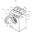
- FIG. 1 is a perspective view of a washing machine 100 in accordance with a first embodiment of the present invention.
- FIG. 3 is a perspective view of a washing machine 102 in accordance with a second embodiment of the present invention.
- FIG. 7 is a perspective view of a further washing machine 103.
- the washing machine 100, 102, 103 in accordance with the several embodiments described in the following includes an enclosure, which may also be referred to as a main body 111, forming an external appearance of the washing machine 100, 102, 103, a door 112 configured to allow laundry to be put into the main body 111 by opening and closing one side of the main body 111, a washing tub 120 disposed within the main body 111 to receive laundry for washing, a control panel 116 for user interface, and a processor (105 of FIGs. 2 , 4 , 8 ) for executing instructions causing the washing machine to perform steps of methods related to washing operations.
- an enclosure which may also be referred to as a main body 111, forming an external appearance of the washing machine 100, 102, 103, a door 112 configured to allow laundry to be put into the main body 111 by opening and closing one side of the main body 111, a washing tub 120 disposed within the main body 111 to receive laundry for washing, a control panel 116 for user interface, and
- the washing machine 100, 102, 103 may include a wash aid box 114.
- the wash aid box 114 may be slidingly engaged within a dispenser in the main body 111 or fixed within the main body 111.
- the wash aid box 114 may be removable by a user while in other embodiments, the wash aid box 114 may not be removable by the user.
- the washing machine 100 may receive a detachable wash aid container 200 on a top surface of the main body 111.
- the washing machine 102 may receive a detachable liquid wash aid module 184 on a top surface of the main body 111.
- the liquid wash aid module 184 may receive a detachable wash aid container 200 on a top surface thereof.
- a wash aid container 200 may be placed on a surface near the washing machine, such as a shelf above the washing machine. Of course, nothing would prevent the wash aid container 200 from being placed on the top surface of the main body 111 of the washing machine 103 itself.
- FIG. 2 is a side cross-sectional view of the washing machine in accordance with the embodiment of FIG. 1 .
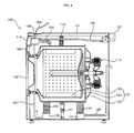
- FIG. 4 is a side cross-sectional view of the washing machine in accordance with the embodiment of FIG. 3 .
- FIG. 8 is a side cross-sectional view of the washing machine in accordance with the embodiment of FIG. 7 .
- the washing tub 120 accommodates laundry, liquid wash aid, and wash water during washing.
- the washing tub may be disposed within the main body 111 so as to be buffered by a spring 114 and a damper 117.
- the washing tub 120 preferably includes a drum 122 configured to contain wash water and wash aid, a tub 124 rotatably disposed within the drum 122, accommodating laundry, and having a plurality of holes, through which the wash water and wash aid in the drum 122 are free to pass through, and a lifter 126 disposed on an inner surface of the tub 124 to lift the laundry to a predetermined height during rotation of the tub 124 and then drop the same.
- the tub 124 may be rotated by a rotational force of a driving unit 113 coupled thereto and provided inside the main body 111.
- a mixing unit 133 may be provided between the water supply valve 131 and the first water supply passage 132.
- the wash water introduced through the water supply valve 131 may be mixed with liquid wash aid from the wash aid container 200 in the mixing unit 133 prior to the passage of the combined wash water and liquid wash aid through the first water supply passage 132.
- the liquid wash aid from the wash aid container 200 could be directed to the wash aid box 114 without use of a separate mixing unit 133 as illustrated in the embodiment of FIG. 7 .
- the wash water introduced through the water supply valve 131 may be mixed with liquid wash aid from the wash aid container 200 in the wash aid box 114.
- a circulation bellows 135 through which the wash water and liquid wash aid in the drum 122 are circulated, a circulation pump 136 configured to moving the wash water and liquid wash aid, and a circulation passage 137 through which the wash water and liquid wash aid flows may be provided in the main body 111. Water circulates in the direction of the arrow, as shown in the circulation passage 137.
- a discharge bellows 141 through which the wash water and liquid wash aid in the drum 122 are discharged, a discharge pump 142 configured to discharging the wash water and liquid wash aid, and a discharge passage 143 through which the wash water and liquid wash aid are discharged to the outside are also preferably provided in the main body 111.
- washing machines 100, 102, 103 including the washing tub 120 and main body 111, may be modified by those skilled in the art.
- the various embodiments may further comprise a flexible conduit 164 that may fluidly couple wash aid from the wash aid container 200 to the wash aid box 114.
- the flexible conduit 164 may comprise flexible and/or rigid or semi-rigid tubing.
- the various embodiments may further comprise a wash aid control unit 168 configured to control and/or meter the flow of the liquid wash aid passing from the wash aid container 200 to the wash aid box 114.
- the wash aid container 200 may be a commercially available container and may be used as-is, without modification. Alternatively, the liquid wash aid may be stored in a container adapted for such a purpose for the washing machine.
- the top surfaces of the washing machine 100 and the wash aid supply module 184 may be formed to stably receive a wash aid container 200.
- the top surfaces may include a wash aid container fixing unit 185 for fixing the wash aid container 200 to the washing machine 100 or the wash aid supply module 184, respectively.
- the wash aid container fixing unit 185 may be formed in various shapes according to the shape of the wash aid container 200 and may, for example, fix one or more sides, including the bottom, of the wash aid container 200 to the washing machine 100 or the wash aid supply module 184, respectively.
- the top surfaces of the washing machine 100 and the wash aid supply module 184 may be formed to accommodate a plurality of wash aid containers 200.
- the plurality of containers may have different shapes.
- the plurality of wash aid containers 200 may individually contain a washing detergent, a cleaning detergent (e.g., fabric softener), and a bleaching liquid, respectively.
- portions of the top surfaces of the washing machine 100 and the wash aid supply module 184 may be formed to match the shape of portions of one or more surfaces of the wash aid container 200.
- a depression corresponding to an outer shape of a portion of a wash aid container 200 may be formed in the top surface in order to receive the wash aid container 200.
- portions of the top surfaces of the washing machine 100 and wash aid supply module 184 may be formed of an elastic member capable of matching with or conforming to the shape of a wash aid container 200 placed thereon.
- the flexible conduit 164 may extend out from the rear of the wash aid supply module 184 and connect to an interface 165 on the rear of the main body 111.
- the interface 165 may allow a user to conveniently connect or disconnect the flexible conduit 164 to or from the washing machine 102.
- the interface 165 may also receive an electrical connection 166 that may carry power and/or control signal(s) to electrically operated components of the wash aid supply module 184.
- the electrical connection may couple, for example, the processor 105 to these electrically operated components of the wash aid supply module 184.
- the flexible conduit 164 may extend from one or more wash aid containers 200 placed on, for example, a shelf 10 on a wall near washing machine 103, to the washing machine 103.
- the flexible conduits 164 may be coupled to the main body 111 of washing machine 103 via mechanical couplings or even via through-holes in the upper surface 350 ( FIG. 9 ) of the washing machine 103.
- a plurality of flexible conduits 164 are disposed to pass through through-holes 179 formed through an upper surface 350 of the main body 111 of the washing machine 103.
- a wash aid control unit 168 may be disposed at an end of each of the flexible conduits 164.
- the wash aid control unit 168 are disposed at the ends of the flexible conduits 164 on the inside of the main body 111.
- Various placements of wash aid control units 168 and coupling methods of wash aid control units 168 to flexible conduits 164 and/or the main body 111 may be selected by those of skill in the art without departing from the scope of the invention.
- each flexible conduit 164 may include a wash aid control unit 168 to control the flow of the wash aid that passes through the flexible conduit 164.
- the wash aid control unit 168 may be implemented as a tube-pump or some other type of pump or a valve. In one embodiment, a peristaltic pump, a class of tube-pump, is used.
- the wash aid control unit 168 may regulate the amount of wash aid discharged from an associated wash aid container 200, such that the amount of wash aid identified by an instruction executed by the processor 105 is delivered to the wash aid box 114.
- the wash aid control unit 168 may be controlled automatically via an interface to the processor 105. In some embodiments, the wash aid control unit 168 may be controlled by a user from the control panel 116.
- the wash aid discharged from the flexible conduit 164 may be supplied to the wash aid box 114.
- the wash aid box 114 may be partitioned into compartments to accommodate different types of wash aids, such as washing liquid detergent, rinsing liquid detergent (e.g., fabric softener), and bleaching liquid.
- the wash aid delivered to the wash aid box 114 may be mixed with washing water as described above, and then introduced into the tub 122 through the second water supply passage 134.
- the flexible conduits 164 may be adjusted in length such that the length of the flexible conduits 164 correspond to the distances separating the wash aid containers 200, for example, from the through holes 179 in the washing machine 103.
- the flexible conduit 164 may be formed of a material having a shape memory, such that when it is released from being stretched it will spring back to its original or near to its original form.
- the flexible conduits 164 may be formed in a coil so as to allow for extension or retraction without excess flexible conduit 164 left lying about. Such a configuration may allow for self-adjustment of length and may be convenient for adapting to different distances between the washing machine 103 and the remotely placed wash aid containers 200.
- flexible conduits 164 may be implemented in a variety of ways, such as winding the flexible conduits on a roller or the like, without being limited thereto.
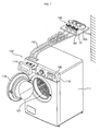
- FIG. 5 is a rear perspective view of the washing machine 102 in accordance with the embodiment of FIG. 3 .
- FIG. 5 illustrates the wash aid supply module 184 in a partially raised state.
- the wash aid supply module 184 may be connected to the top rear surface of the main body 111 by a hinge 119.
- the rear surface of the wash aid supply module 184 may be detachably connected to the main body 111 of the machine 103 via the hinge 119.
- the wash aid supply module 184 may be tilted with respect to the main body 111 by the hinge 119.
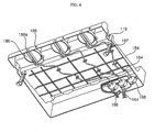
- FIG. 6 is a bottom perspective view of the wash aid supply module 184 in accordance with the embodiment of FIG. 3 .
- a support unit 187 may be included in the wash aid supply module 184.
- the support unit 187 may be rotatably coupled to the wash aid supply module 184.
- the support unit 187 may be configured to support the wash aid supply module 184 in a partially raised state, spaced apart at an angle from the main body 111 of washing machine 102. In this state, a user may gain access to components on the underside of the wash aid supply module. Access may be needed, for example, to allow for cleaning of certain components, such as reservoir 186. Access to reservoir 186 may provide beneficial convenience to a user in that the reservoir 186 may require cleaning.
- Access may be especially desired if the reservoir 186 is made, in total or in part, from transparent material. If made from transparent material, the reservoir 186 may require cleaning so as not to lose its transparency. Having the wash aid supply module 184 adapted to tilt upward at some angle, and maintain the separation between the wash aid supply module 184 and the top surface of the washing machine 102, will allow a user to gain access to the reservoir 186. Access may be required to remove the reservoir 186 from the wash aid supply module 184 for cleaning or replacement. Other mechanisms of supporting the supply module 184 in an open or tilted state are within the scope of the invention. For example, the hinge 119 may be designed to hold the supply module 184 in a tilted state without a need for support unit 187.
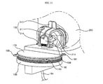
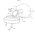
- FIG. 11 is a perspective view of a reservoir 186 coupled to a liquid wash aid supply container in accordance with the embodiments of either FIG. 1 or FIG. 3 .
- the reservoir 186 includes a cylindrical portion that includes a threaded interior portion 188.
- the threaded interior portion 188 mates with a threaded exterior portion of a corresponding cylindrical body extending downward from an underside of the wash aid supply module 184.
- a user may unscrew the reservoir 186 from the underside of the wash aid supply module 184, to detach the reservoir 186 therefrom.
- the flexible conduit 164 may couple to the bottom of the reservoir 186.
- FIG. 6 illustrates the placement of three reservoirs 186 on the underside of the wash aid supply module 184. Similar to the embodiment illustrated in FIG. 11 , the reservoirs 186 of FIG. 6 may also be detached from the wash aid supply module 184 by rotating the body of the reservoir 186 to unscrew it from the wash aid supply module 184.
- the wash aid supply module 184 may include a tab 119 ( FIG. 6 ) to engage a latch 118 ( FIG. 3 ) and thereby enable the wash aid supply module 184 to be secured to the main body 111 of washing machine 102.
- the main body 111 of washing machine 102 may include a tab (similar to 119) or slot (not shown) to engage a latch or other mechanism (similar to 118) on the wash aid supply module 184 and thereby secure the wash aid supply module 184 to the main body 111 of washing machine 102.
- the incorporation of various features to secure the wash aid supply module 184 to the washing machine 102 may be know to those of skill in the art and are within the scope of the invention.
- a washing machine 100, 102 may include a reservoir 186.
- the reservoir 186 may be located in the main body 111.
- reservoir 186 may be included on an underside of the wash aid supply module 184.
- the reservoir 186 may be located toward a front of the wash aid supply module 184.
- the reservoir 186 is be detachably coupled to allow, for example, for removal, cleaning, and replacement.
- the reservoir 187 (similar to 186) may be located remotely from the washing machine 103.
- the reservoir 186 used in the embodiments of FIGs. 1 and 3 are similar to the reservoir 187 used in the embodiment of FIG. 7 .
- Reservoirs 186, 187 may be configured to temporarily store liquid wash aid drawn from the wash aid container 200.
- the reservoir 186, 187 temporarily stores at least an amount of liquid wash aid required to perform a washing operation at least once, even if the liquid wash aid in the wash aid container 200 is exhausted (e.g., the wash aid container 200 has just emptied).
- a plurality of reservoirs 186, 187 are provided. Most preferably, at least one reservoir 186, 187 is provided for each wash aid container 200. In each of the exemplary embodiments described herein, three reservoirs 186, 187 are provided.
- the reservoir 186, 187 may be formed of a transparent material so that the residual amount of wash aid stored in the reservoir 186 may be viewed by a user. Viewing may be aided by viewing ports 186a on the washing machine 100 according to the first embodiment, and on the wash aid supply module 184 of washing machine 102 according to the second embodiment.
- a wash aid reservoir 186, 187 is not made of a transparent material overall, it may include a display window made of a transparent material to show (indicate) the remaining amount of the wash aid in the wash aid reservoir 186, 187.
- the reservoir 186, 187 may include a viewing port 186a to allow for observation of the amount of liquid wash aid introduced from the wash aid container 200.
- the viewing port 186a may be implemented by a transparent material to permit observation of the remaining amount of the wash aid.
- a function of determining the remaining amount of wash aid may be implemented by a device 1720 ( FIG. 17 ) capable of detecting the amount of liquid in the reservoir 186, 187 such as an electronic sensor, an electrode sensor, a magnetic sensor, a floating device, etc.
- a wash aid control unit 168 may be provided in series with the flexible conduit 164.
- the wash aid control unit 168 may act to control, or meter, the flow of the liquid wash aid passing through the flexible conduit 164.
- the wash aid control unit 168 may be implemented by a valve, and preferably by a pump capable of moving the liquid wash aid through the flexible conduit 164.
- the wash aid control unit 168 may be a tube pump, also known as a peristaltic pump.
- the pump may be configured so as not to need any priming.
- the wash aid control unit 168 may be implemented by a pump configured to positively or negatively pressurize the liquid wash aid in the flexible conduit 164.
- the wash aid control unit 168 may be controlled by the controller 105. When operated by the controller 105, the wash aid control unit 168 may be configured to control the amount of liquid wash aid supplied to the washing tub 120 according to, for example, the amount of laundry and water in the washing tub 120, and a predetermined washing course that may be selected by a user.
- the wash aid control unit 168 may be provided on a rear inside surface of the main body 111.
- the flexible conduit 164 may be connected at one end to the wash aid control unit 168 and at the other end to the reservoir 186.
- the wash aid control unit 168 may be provided on the rear inside surface of the wash aid supply module 184. Similar to the embodiment of FIG. 2 , the flexible conduit 164 may be connected at one end to the wash aid control unit 168 and at the other end to the reservoir 186.
- the wash aid control unit 168 may be provided at a far end of the flexible conduit 164 and may be positioned above the wash aid box 114, as illustrated in FIGs. 8 and 9 . Alternate placements of the wash aid control unit 168 in each of the various embodiments are within the scope of the invention.
- FIG. 10 is a perspective view of a portion of an upper surface of a washing machine according to the embodiment of FIG. 1 or a wash aid supply module 184 according to the embodiment of FIG. 3 .
- FIG. 11 is a perspective view of a reservoir 186 coupled to a liquid wash aid supply container 200 in accordance with the embodiments of either FIG. 1 or FIG. 3 .
- the reservoir 186 is threaded onto a reservoir receiving portion 178.
- the reservoir receiving portion 178 may be connected via screws (not shown) through flanges 190 into the underside of the top of the washing machine 100 or the wash aid supply module 184.
- FIG. 10 is a perspective view of a portion of an upper surface of a washing machine according to the embodiment of FIG. 1 or a wash aid supply module 184 according to the embodiment of FIG. 3 .
- FIG. 11 is a perspective view of a reservoir 186 coupled to a liquid wash aid supply container 200 in accordance with the embodiments of either FIG. 1 or FIG. 3 .
- FIG. 12 is a perspective view of a container connecting assembly 192 in accordance with an embodiment of the invention.
- FIG. 13 is a perspective view showing alignment of a liquid wash aid container 200 and a reservoir 187. In the embodiments of FIGs. 12 through 13 , the reservoir 187 is combined with a container connecting assembly 192.
- FIG. 14 is a perspective view showing a liquid wash aid container 200 coupled to a reservoir 167, where a container connecting assembly 192 is secured to the spout assembly of the wash aid container 200.
- a container connecting assembly 192 may be implemented to mechanically couple the wash aid container 200 to the reservoir 186, 187.
- the container connecting assembly 192 includes a spout fixing unit 311 configured to fix a spout 310 ( FIG.
- a button depressing unit 312 configured to push down a mechanically operated valve 210 of the wash aid container 200
- a handle 313 configured to allow a user to rotate the spout fixing unit 311 by hand
- a rotary connection unit 314 configured to rotatably connect the spout fixing unit 311 and the reservoir 186, 187 so that the spout fixing unit 311 can be rotated about the connection unit 314 and capture a portion of the container 200.
- the spout fixing unit 311 fixes the spout 310 of the wash aid container 200 to the reservoir 186, 187 and may be formed in various shapes according to the shape of the spout assembly of the wash aid container 200.
- the spout fixing unit 311 has a squared "C" or "U” shape, which is open at one side and closed on the remaining three sides. In the embodiments illustrated, the open portion of the spout fixing unit 311 receives the spout assembly of the wash aid container 200.
- Wedge shaped protrusions 315 at the ends of the spout fixing unit 311 may snap into corresponding slots 316 on the top of the washing machine 100, the top of the wash aid supply module 184, or the top of the reservoir 187, thereby releasably securing the spout assembly of the wash aid container 200 within the spout fixing unit 311.
- the button depressing unit 312 may be provided to depress the mechanically operated valve 210 when fixing the wash aid container 200 to the reservoir 186, 187.
- the button depressing unit 312 may be formed in various shapes according to the position and shape of the mechanically operated valve 210.
- the button depressing unit 312 may formed in a dome shape that protrudes from the bottom of the spout fixing unit 311.
- the handle 313 may be provided to allow the user to rotate the spout fixing unit 311 of the container connecting assembly 192.
- the handle 313 and has a flat shape formed in a direction perpendicular to the spout fixing unit 311.
- the rotary connection unit 314 rotatably connects spout fixing unit 311 of the container connecting assembly 192 to an upper surface of the washing machine 100, an upper surface of the wash aid supply module 184, or an upper surface of a reservoir 187.
- the spout fixing unit 311 rotates about the axis of the rotary connection unit 314, thus allowing the spout assembly of the wash aid container 200 to be secured therebetween.
- the container connecting assembly 192 may further include a cover unit 196 configured to open and close or otherwise uncover or cover the liquid wash aid spout inlet 194.
- the cover unit 196 may be provided to cover the liquid wash aid inlet 194 in case no wash aid container 200 is seated on the top surface of the washing machine 100, the top surface of the wash aid supply module 184, or the top surface of the reservoir 187.
- the cover unit 196 may be part of the assembly of the container connecting assembly 192.
- the rotary connection unit 314 may act as a hinge pin, passing through a cooperating receiving portion of the cover unit 196 substantially as shown in the exemplary illustrations of FIGs. 10 through 14 .
- the container connecting assembly 192 provides identification marks in accordance with the kinds of liquid wash aid containers 200 coupled thereto.
- the container connecting assembly 192 may provide different colors in accordance with the kinds of the liquid wash aid containers including a washing detergent wash aid container, a cleaning detergent wash aid (e.g., fabric softener) container, a bleaching liquid wash aid container, etc.
- a washing detergent wash aid container e.g., fabric softener
- a bleaching liquid wash aid container e.g., fabric softener
- the above-described structure of the container connecting assembly 192 may be modified in various ways according to the shape of the wash aid container 200 by those skilled in the art.
- the top surface of the washing machine 100, the top surface of the wash aid supply module 184, and the top surface of the reservoir 187 may include a spout inlet 194, into which the spout 310 of the liquid wash aid container 200 is fixed and through which the liquid wash aid drawn from the wash aid container 200 is introduced into the reservoir 186, 187.
- a resilient temporary or permanent seal such as an O-ring or a flat circular washer, may be provided between the spout 310 (or spout assembly) and the spout inlet 194 in order to provide a leak-proof or leak-resistant seal therebetween.
- a plurality of liquid wash aid spout inlets 194 may be provided to correspond to the number of liquid wash aid containers 200 and reservoirs 186.
- three liquid wash aid spout inlets 194 are provided.
- the liquid wash aid introduced into the liquid wash aid spout inlet 194 is stored in a corresponding reservoir 186, 187.
- the washing machine 100, 102 in accordance with various embodiments of the present invention may include a concentration selection unit 189 configured to select/indicate the concentration of the liquid wash aid stored in the wash aid container 200.
- the concentration selection unit 189 may allow a user to select the concentration of liquid wash aid according to the kind of liquid wash aid. In the case where the liquid wash aid is double-concentrated, the concentration selection unit 189 may be set to select a "double" as the concentration. Then, the wash aid control unit 168, under the control of the processor 105, controls the amount of liquid wash aid supplied to the washing tub 120 according to the concentration selected by the concentration selection unit 189.
- the washing machine 100, 102, 103 in accordance with the various embodiments described, may include a concentration selector 182 on the control panel 116 of the washing machine 100, 102, 103. The concentration selection unit 189 and/or the concentration selector 182 may interface to the processor 105.
- FIG. 15 is a perspective view showing an alternate embodiment of a liquid wash aid container 201 coupled to a wash aid reservoir 188 in accordance with another embodiment of the invention.
- a wash aid container coupling unit 392 may be configured to couple a generic wash aid container 201 to a wash aid reservoir 188 (similar to 186 and 187), even though the spouts of generic wash aid containers vary in shape.
- a wash aid container coupling unit 390 includes a spout coupling part 391 adapted to couple to a spout 220 of a generic wash aid container 201, a guiding part 392 adapted to guide wash aid discharged from the spout 220, and an inlet coupling part 393 adapted to couple the guiding part 392 to a wash aid spout inlet 194 of a reservoir 188.
- the spout coupling part 391 may be embodied to vary in its shape so as to correspond to the shape of a variety of spouts of generic wash aid containers.
- the method for implementing the spout coupling part 391, such that its shape can vary, may be implemented by an ordinary person in the art to which the present invention pertains.
- the spout coupling part 391 may be implemented by using an elastic material so as to be inserted into or around container spouts that may have various shapes and sizes.
- FIG. 16 is a flow diagram of a method of use of a washing machine in accordance with an embodiment of the invention. The operation of the above-described washing machine 100, 102, 103 and a washing method will be described below with reference to FIG. 16 .
- the method may start.
- the wash aid container 200 may be seated on the top surface of the washing machine 100 according to the embodiment of FIG. 1 , on the top surface of the wash aid supply module 184 according to the embodiment of FIG. 3 , or on any surface according to the embodiment of FIG. 7 .
- the container connecting assembly 192 fixes the wash aid container 200 and, when the mechanically operated valve 210 is depressed, the liquid wash aid in the wash aid container 200 is supplied to the reservoir 186, 187.
- the supplied liquid wash aid is temporarily stored in the reservoir 186, 187.
- the door 112 is opened and laundry is put into the tub 124 of the washing tub 120.
- the washing machine 100, 102, 103 is operated after closing the door 112
- the amount of laundry put into the tub 124 may be detected, and the water level, the amount of liquid wash aid to be supplied, the washing time, etc. are determined by operation of the processor 105.
- a predetermined amount of wash water is supplied from an external water source.
- the wash aid control unit 168 is operated according to commands executed by the processor 105, a predetermined amount of the liquid wash aid stored in the reservoir 186, 187 is supplied to the wash water.
- a washing liquid wash aid e.g., laundry detergent
- the liquid wash aid stored in the reservoir 186 is introduced into the mixing unit 133 through the flexible conduit 164.
- the liquid wash aid stored in the reservoir 187 is introduced into the wash aid box 114 through the flexible conduit 164. Variations of these combinations are within the scope of the invention.
- the wash water and liquid wash aid are mixed in the mixing unit 133 and/or the wash aid box 114, and introduced into the tub 124 and drum 122 of the washing tub 120 via the second water supply passage 134.
- the driving unit 113 operates to rotate/agitate the laundry in the tub 124 for a predetermined time in accordance with the determined washing machine parameters.
- the wash water and liquid wash aid may be circulated in and out of the washing tub 120 by the circulation pump 136.
- the operation of the driving unit 113 is stopped, and the discharge pump 142 operates to discharge the wash water and liquid wash aid used during the washing cycle to the outside.
- the method returns to 1608 and/or 1610, respectively, whereupon the water supply valve 131 is opened to supply wash water from the external water source, and the wash aid control unit 168 operates to supply a predetermined amount of a cleaning liquid wash aid (e.g., fabric softener).
- a cleaning liquid wash aid e.g., fabric softener
- the wash water and liquid wash aid are mixed as described above and introduced into the washing tub 120 via the second water supply passage 134.
- the driving unit 113 operates to rotate the tub 124 for a predetermined time according to determined the washing machine operating parameters, thus performing a rinsing cycle.
- the wash water and liquid wash aid may be circulated in and out of the washing tub 120 by the circulation pump 136.
- the operation of the driving unit 113 is stopped, and the discharge pump 142 operates to discharge the wash water and liquid wash aid to the outside.
- a dehydrating cycle and a drying cycle may be performed according to a predetermined schedule as determined by the washing machine operating parameters.
- the method may end.
- a user may observe if the amount of liquid wash aid stored in the reservoir 186, 187 is insufficient to perform the washing cycle.
- the user need only observe the viewing port 186a associated with the reservoir 186. If the amount is nearly insufficient or is insufficient, the user may replace the empty wash aid container 200 with a full container.
- FIG. 17 is a schematic representation of a control system of a washing machine in accordance with an embodiment of the invention.
- a control system in accordance with an embodiment of the invention may include: a processor 105; a control panel interface 1702 coupled to a control panel 116 for both receiving input from a user and to display output to a user; a memory 1704 for storing instructions corresponding to a method, the instructions to be executed by the processor 105; one, or more than one, communication interfaces 1706a, 1706b, 1706c coupled to one or more wash aid controllers 168a, 168b, 168c; a communication interface 1708 coupled to a water supply valve 131; a communication interface 1710 coupled to a motor 113; a communication interface 1712 coupled to a circulation pump 136; a communication interface 1714 coupled to a concentration selection unit 189,; a communication interface 1716 coupled to a concentration selection unit 189, and a communication interface coupled to a level detector 1718, all coupled to a communications bus 1720.
- the washing machine according to the present invention provide at least one of the following effects.
- liquid wash aid container containing liquid wash aid can be used as-is by connecting the same to the washing machine, and thus the user's convenience is improved.
- the liquid wash aid container can be conveniently detached.
- the supply module 184 which receives and connects to the liquid wash aid containers is formed as a module, separate from the main body of the washing machine, it may be added subsequent to an original purchase of the washing machine 102, removed from the washing machine 102, and lifted/tilted above the top of the washing machine 102 to allow for service of components on its underside.
Landscapes
- Engineering & Computer Science (AREA)
- Textile Engineering (AREA)
- Detail Structures Of Washing Machines And Dryers (AREA)
Claims (12)
- System, das umfasst:eine Umschließung (111);eine Trommel (122), die in der Umschließung (111) untergebracht ist;eine Mischeinheit (133), die in der Umschließung (111) getrennt von der Trommel (122) untergebracht ist und mit der Trommel (122) in Fluidkommunikation ist;eine Wasserzufuhreinheit, die mit der Mischeinheit (133) gekoppelt ist;einen Vorratsbehälter (186) mit einer Leitung, die konfiguriert ist, den Vorratsbehälter (186) mit der Mischeinheit (133) fluidtechnisch zu koppeln;eine Behälterverbindungsanordnung (192), die konfiguriert ist, einen Auslauf (310) eines Behälters (200) an dem Vorratsbehälter (186) zu befestigen; undBeobachtungsöffnungen (186a) zum Beobachten der Menge einer flüssigen Waschhilfe, die in dem Vorratsbehälter (186) gespeichert ist, wobei:der Behälter (200) an der Umschließung (111) abnehmbar befestigt ist oderder Behälter (200) an einem Zufuhrmodul (184) abnehmbar befestigt ist und das Zufuhrmodul (184) an der Umschließung (111) abnehmbar befestigt ist,wobei die Beobachtungsöffnungen (186a) vorhanden sind an:der Umschließung (111), falls der Behälter (200) an der Umschließung (111) abnehmbar befestigt ist, oder an dem Zufuhrmodul (184), falls der Behälter (200) an dem Zufuhrmodul (184) abnehmbar befestigt ist;wobei sich der Vorratsbehälter (186) in der Umschließung (111) befindet und mit der Umschließung (111) lösbar gekoppelt ist, falls der Behälter (200) an der Umschließung (111) abnehmbar befestigt ist, oder an einer Unterseite des Zufuhrmoduls (184) vorhanden ist und mit dem Zufuhrmodul (184) lösbar gekoppelt ist, falls der Behälter (200) an dem Zufuhrmodul (184) abnehmbar befestigt ist; undwobei der Vorratsbehälter (186) teilweise oder vollständig lichtdurchlässig ist, um eine Beobachtung eines Pegels der Inhalte des Vorratsbehälters durch die Beobachtungsöffnungen (186a) zu ermöglichen.
- System nach Anspruch 1, wobei die Behälterverbindungsanordnung (192) ferner konfiguriert ist, ein Ventil (210) des Behälters (200) in einer geöffneten Stellung zu halten, um eine unbeeinträchtigte Strömung der Behälterinhalte in den Vorratsbehälter (186) zu ermöglichen, wenn der Auslauf (310) des Behälters (200) an dem Vorratsbehälter (186) befestigt ist.
- System nach Anspruch 1, wobei der Auslauf (310) des Behälters (200) an dem Vorratsbehälter (186) abnehmbar befestigt ist.
- System nach Anspruch 1, das ferner eine Pumpe (168) umfasst, die konfiguriert ist, ein abgemessenes Flüssigkeitsvolumen von dem Vorratsbehälter (186) an die Mischeinheit (133) zu übertragen.
- System nach Anspruch 1, wobei entweder eine obere Oberfläche der Umschließung (111) oder eine obere Oberfläche des Zufuhrmoduls (184) konfiguriert ist:den Behälter (200) in einer einteilig ausgebildeten Aussparung aufzunehmen undden Behälter (200) in einer Stellung zu halten, derart, dass die Schwerkraft bewirkt, dass die flüssigen Inhalte des Behälters aus dem Behälterauslauf (310) auslaufen, um die flüssigen Inhalte des Behälters (200) zu entleeren oder nahezu zu entleeren.
- System nach Anspruch 1, das ferner umfasst:einen Vorratsbehälter-Aufnahmeabschnitt (178), wobei der Vorratsbehälter-Aufnahmeabschnitt (178) verbunden ist mit:der Umschließung (111), falls der Behälter (200) an der Umschließung (111) abnehmbar befestigt ist, oderdem Zufuhrmodul (184), falls der Behälter (200) an dem Zufuhrmodul (184) abnehmbar befestigt ist; undder Vorratsbehälter (186) mit dem Vorratsbehälter-Aufnahmeabschnitt (178) abnehmbar verbunden ist.
- System nach Anspruch 1, wobei das Zufuhrmodul (184) umfasst:ein Behälterbefestigungsteil (185), das konfiguriert ist, den Behälter (200) an dem Zufuhrmodul (184) abnehmbar zu befestigen;einen Vorratsbehälter-Aufnahmeabschnitt (178), der mit einer Unterseite des Zufuhrmoduls (184) verbunden ist, wobei der Vorratsbehälter (186) mit dem Vorratsbehälter-Aufnahmeabschnitt (178) abnehmbar verbunden ist.
- System nach Anspruch 7, das ferner eine Scharnieranordnung (119) umfasst, die konfiguriert ist, das Zufuhrmodul (184) mit der Umschließung (111) so zu koppeln, dass das Zufuhrmodul (184) um eine Arbeitsachse der Scharnieranordnung (119) schwenken kann, um einen Zugang zu der Unterseite des Zufuhrmoduls (184) zu erlangen.
- System nach Anspruch 8, das ferner eine Trageinheit (187) umfasst, die mit dem Zufuhrmodul (184) drehbar gekoppelt ist, wobei die Trageinheit (187) konfiguriert ist, das Zufuhrmodul (184) in einem teilweise erhöhten Zustand und von der Umschließung (111) um einen Winkel beabstandet zu tragen.
- System nach Anspruch 1, das ferner umfasst:einen Einlass (194) für flüssige Waschhilfe, um den Auslauf (310) des Behälters (200) aufzunehmen; undeine Abdeckeinheit (196), die konfiguriert ist, den Einlass (194) für flüssige Waschhilfe abzudecken, wenn der Auslauf (310) nicht darin aufgenommen ist.
- System nach Anspruch 1, das ferner eine Konzentrationsauswahleinheit (189) umfasst, die vorgesehen ist, um die Konzentration einer in dem Behälter (200) enthaltenen Flüssigkeit auszuwählen.
- System nach Anspruch 1, wobei die Behälterverbindungsanordnung (192) Identifizierungsmarkierungen in Übereinstimmung mit den Arten von damit gekoppelten Behältern (200) für flüssige Waschhilfe bereitstellt.
Applications Claiming Priority (3)
| Application Number | Priority Date | Filing Date | Title |
|---|---|---|---|
| KR20080124852A KR101492097B1 (ko) | 2008-12-09 | 2008-12-09 | 세탁기 |
| KR20080124851A KR101490169B1 (ko) | 2008-12-09 | 2008-12-09 | 세탁기 및 세탁 방법 |
| KR20080124850A KR101490168B1 (ko) | 2008-12-09 | 2008-12-09 | 세탁기 및 세탁 방법 |
Publications (2)
| Publication Number | Publication Date |
|---|---|
| EP2196574A1 EP2196574A1 (de) | 2010-06-16 |
| EP2196574B1 true EP2196574B1 (de) | 2015-09-09 |
Family
ID=41818294
Family Applications (1)
| Application Number | Title | Priority Date | Filing Date |
|---|---|---|---|
| EP09008225.6A Not-in-force EP2196574B1 (de) | 2008-12-09 | 2009-06-23 | Waschmaschinenvorrichtung |
Country Status (3)
| Country | Link |
|---|---|
| US (2) | US8555678B2 (de) |
| EP (1) | EP2196574B1 (de) |
| CN (1) | CN101748578B (de) |
Families Citing this family (41)
| Publication number | Priority date | Publication date | Assignee | Title |
|---|---|---|---|---|
| KR101482108B1 (ko) | 2008-05-23 | 2015-01-13 | 엘지전자 주식회사 | 세탁기 |
| US8756959B2 (en) * | 2009-09-28 | 2014-06-24 | Alliance Laundry Systems, Llc | Chemical injection dispenser and cap |
| DE102010027991A1 (de) * | 2010-04-20 | 2011-10-20 | Henkel Ag & Co. Kgaa | Dosiersystem zur Verwendung in Verbindung mit einem wasserführenden Haushaltsgerät wie eine Waschmaschine, Spülmaschine, Wäschetrockner oder dergleichen |
| DE102010027992A1 (de) * | 2010-04-20 | 2011-10-20 | Henkel Ag & Co. Kgaa | Dosiersystem zur Freisetzung von wenigstens drei unterschiedlichen Zubereitungen während eines Waschprogramms einer Waschmaschine |
| CH703349B1 (de) * | 2010-06-29 | 2013-12-13 | V Zug Ag | Waschmaschine mit Waschmittel-Dosiervorrichtung. |
| DE102010043418B3 (de) * | 2010-11-04 | 2012-02-09 | BSH Bosch und Siemens Hausgeräte GmbH | Wasserführendes Hausgerät mit einer Gebindeaufnahme |
| US20140053344A1 (en) * | 2012-08-21 | 2014-02-27 | Pellerin Milnor Corporation | Washer extractor apparatus and method |
| KR102210011B1 (ko) | 2013-09-05 | 2021-02-01 | 삼성전자주식회사 | 세탁기 및 그 제어방법 |
| WO2015161548A1 (zh) * | 2014-04-22 | 2015-10-29 | 无锡小天鹅股份有限公司 | 洗衣机及其自动投放系统 |
| CN105088686A (zh) * | 2014-04-22 | 2015-11-25 | 无锡小天鹅股份有限公司 | 洗衣机及其自动投放系统 |
| WO2015161606A1 (zh) * | 2014-04-22 | 2015-10-29 | 无锡小天鹅股份有限公司 | 洗衣机及其自动投放系统 |
| WO2015161607A1 (zh) * | 2014-04-22 | 2015-10-29 | 无锡小天鹅股份有限公司 | 洗衣机及其自动投放系统 |
| EP2995710B1 (de) * | 2014-09-15 | 2018-07-11 | Electrolux Appliances Aktiebolag | Waschmaschine |
| US10655264B2 (en) | 2015-08-04 | 2020-05-19 | Whirlpool Corporation | Laundry treating appliance with internal housing |
| JP2017074082A (ja) * | 2015-10-13 | 2017-04-20 | 日立アプライアンス株式会社 | 洗濯機 |
| CN106854812A (zh) * | 2015-12-09 | 2017-06-16 | 无锡小天鹅股份有限公司 | 独立式自动投放装置、洗衣机及其控制方法 |
| KR102450182B1 (ko) * | 2016-01-05 | 2022-10-04 | 엘지전자 주식회사 | 세탁물처리장치 및 그의 세탁제공급방법 |
| CN105671877A (zh) * | 2016-04-22 | 2016-06-15 | 青岛中怡智能安全研究院有限公司 | 一种洗涤装置与洗衣机 |
| WO2017205280A1 (en) * | 2016-05-23 | 2017-11-30 | TCD Parts, Inc. | Systems and methods for monitoring sanitation agents in a laundry system |
| IT201600086018A1 (it) * | 2016-08-18 | 2018-02-18 | Illinois Tool Works | Dispositivo ausiliario per l'erogazione di liquidi di lavaggio ad una lavatrice |
| KR102615064B1 (ko) | 2017-01-03 | 2023-12-19 | 삼성전자주식회사 | 세탁 장치 및 세탁 장치의 제어방법 |
| KR102642302B1 (ko) * | 2017-01-03 | 2024-03-04 | 삼성전자주식회사 | 세탁 장치 및 세탁 장치의 제어방법 |
| CN109385841B (zh) * | 2017-08-11 | 2022-07-01 | 青岛海尔洗衣机有限公司 | 洗衣机 |
| CN109385842B (zh) * | 2017-08-11 | 2022-04-26 | 青岛海尔洗衣机有限公司 | 洗衣机 |
| CN107815819A (zh) * | 2017-11-13 | 2018-03-20 | 青岛海尔洗衣机有限公司 | 洗衣机 |
| US10662567B2 (en) | 2017-11-17 | 2020-05-26 | Whirlpool Corporation | Laundry treating appliance having a user interface and methods of operating same |
| US10676855B2 (en) | 2017-11-17 | 2020-06-09 | Whirlpool Corporation | Laundry treating appliance having a user interface and methods of operating same |
| USD848692S1 (en) | 2017-12-21 | 2019-05-14 | Whirlpool Corporation | Bulk dispensing drawer |
| USD899720S1 (en) | 2017-12-21 | 2020-10-20 | Whirlpool Corporation | Laundry treating appliance |
| USD866887S1 (en) | 2017-12-21 | 2019-11-12 | Whirlpool Corporation | Pedestal |
| USD877431S1 (en) | 2017-12-21 | 2020-03-03 | Whirlpool Corporation | User interface |
| USD874764S1 (en) | 2017-12-21 | 2020-02-04 | Whirlpool Corporation | User interface |
| USD865306S1 (en) | 2017-12-21 | 2019-10-29 | Whirlpool Corporation | Laundry treating appliance door |
| KR102594512B1 (ko) | 2018-11-15 | 2023-10-25 | 엘지전자 주식회사 | 세탁기 |
| KR102555839B1 (ko) * | 2018-11-15 | 2023-07-13 | 엘지전자 주식회사 | 세탁기 |
| JP6993381B2 (ja) * | 2019-04-25 | 2022-01-13 | 日立グローバルライフソリューションズ株式会社 | 洗濯機 |
| JP7341862B2 (ja) * | 2019-11-12 | 2023-09-11 | シャープ株式会社 | 洗濯機 |
| IT201900022392A1 (it) | 2019-11-28 | 2021-05-28 | Salros S R L | Composizione di lavaggio liquida a componenti separati, per bucato in macchine lavatrici automatiche |
| JP7285400B2 (ja) * | 2020-02-06 | 2023-06-02 | パナソニックIpマネジメント株式会社 | 洗濯機 |
| CN115595769A (zh) * | 2021-07-07 | 2023-01-13 | 青岛海尔滚筒洗衣机有限公司(Cn) | 一种洗衣机及其控制方法 |
| CN116791336A (zh) * | 2022-03-17 | 2023-09-22 | 洗净加股份有限公司 | 洗涤系统、洗衣机及洗涤用水循环装置 |
Citations (2)
| Publication number | Priority date | Publication date | Assignee | Title |
|---|---|---|---|---|
| US4993457A (en) * | 1990-07-18 | 1991-02-19 | Shop-Vac Corporation | Housing arrangement for a fluid pump and tank |
| US5007254A (en) * | 1989-12-28 | 1991-04-16 | Raytheon Company | Additive fluid viewing |
Family Cites Families (25)
| Publication number | Priority date | Publication date | Assignee | Title |
|---|---|---|---|---|
| US2562843A (en) * | 1946-11-21 | 1951-07-31 | Bohus Mek Verkst S Aktiebolag | Electrical heating apparatus and method |
| US3881328A (en) * | 1971-12-22 | 1975-05-06 | Economics Lab | Electronic detergent dispensing system |
| DE3242382A1 (de) * | 1982-11-16 | 1984-05-17 | Bosch-Siemens Hausgeräte GmbH, 7000 Stuttgart | Geraet mit einrichtungen fuer die bevorratung, dosierung und zugabe von fluessigen wasch- und spuelmitteln |
| DE3302891A1 (de) * | 1982-11-16 | 1984-05-17 | Bosch-Siemens Hausgeräte GmbH, 7000 Stuttgart | Einer automatisch arbeitenden wasch- oder geschirrspuelmaschine beistellbares geraet |
| DE8403009U1 (de) | 1984-02-02 | 1985-07-18 | Bosch-Siemens Hausgeräte GmbH, 7000 Stuttgart | Automatisch gesteuerte Waschmaschine |
| IT215679Z2 (it) * | 1988-01-28 | 1990-10-22 | Zanussi A Spa Industrie | Contenitore erogatore di detersivi liquidi per macchine lavatrici. |
| US5870906A (en) | 1996-04-03 | 1999-02-16 | Denisar; Richard A. | Automatic dispensing device |
| JPH09276589A (ja) | 1996-04-18 | 1997-10-28 | Toshiba Corp | 洗濯機 |
| US6353954B1 (en) | 1999-03-31 | 2002-03-12 | Maytag Corporation | Laundry pretreatment system |
| US6401499B1 (en) | 2000-07-31 | 2002-06-11 | Maytag Corporation | Air pump bulk dispenser |
| US7725970B2 (en) * | 2002-11-25 | 2010-06-01 | Robert J. Tuttle | Control system and method for supplying detergent and other fluids to multiple washing machines |
| KR20050017481A (ko) * | 2003-08-13 | 2005-02-22 | 엘지전자 주식회사 | 증기발생장치를 구비한 드럼세탁기 |
| CA2461225C (en) | 2004-03-17 | 2010-04-20 | Hygiene-Technik Inc. | Self-orientating pump nozzle for fluid dispenser |
| US7398787B2 (en) * | 2004-10-18 | 2008-07-15 | Unilever Home & Personal Care Usa Division Of Conopco, Inc. | Automatic dispensing device for laundry care composition |
| US7481081B2 (en) * | 2004-11-23 | 2009-01-27 | Unilever Home & Personal Care Usa Division Of Conopco, Inc. | Automatic stand-alone dispensing device for laundry care composition |
| US20060117811A1 (en) * | 2004-12-06 | 2006-06-08 | Kinnetz Roger E | Liquid detergent dispensing system for automatic washer |
| AU2004325528B2 (en) | 2004-12-09 | 2009-07-23 | Ecolab Inc. | Detergent dispenser |
| BRPI0710040B1 (pt) | 2006-03-30 | 2017-12-26 | Diversey, Inc. | Chemical product distribution system including chamber linked to chemical product source in powder and method of distribution of liquid and powder chemical product |
| ITTO20060569A1 (it) | 2006-07-31 | 2008-02-01 | Indesit Co Spa | "macchina di lavaggio, in particolare una lavabiancheria, comprendente un dispensatore di agenti di lavaggio a lunga autonomia" |
| WO2008016683A1 (en) | 2006-08-01 | 2008-02-07 | The Procter & Gamble Company | Receiving apparatus |
| US20080276969A1 (en) | 2007-05-07 | 2008-11-13 | Whirlpool Corporation | Appliance with unique locking receptacles |
| DE102007023065A1 (de) | 2007-05-16 | 2008-11-20 | BSH Bosch und Siemens Hausgeräte GmbH | Automatisch gesteuerte Waschmaschine |
| ATE497046T1 (de) * | 2007-07-03 | 2011-02-15 | Electrolux Home Prod Corp | Waschmaschine |
| DE102007048197A1 (de) * | 2007-10-08 | 2009-04-16 | Miele & Cie. Kg | Dosiereinrichtung für Behandlungsmittel für eine Waschmaschine und Waschmaschine |
| KR20090101680A (ko) | 2008-03-24 | 2009-09-29 | 엘지전자 주식회사 | 의류처리장치 |
-
2009
- 2009-04-28 US US12/431,511 patent/US8555678B2/en not_active Expired - Fee Related
- 2009-06-23 EP EP09008225.6A patent/EP2196574B1/de not_active Not-in-force
- 2009-07-14 CN CN200910160460XA patent/CN101748578B/zh not_active Expired - Fee Related
-
2013
- 2013-10-11 US US14/052,195 patent/US9689104B2/en not_active Expired - Fee Related
Patent Citations (2)
| Publication number | Priority date | Publication date | Assignee | Title |
|---|---|---|---|---|
| US5007254A (en) * | 1989-12-28 | 1991-04-16 | Raytheon Company | Additive fluid viewing |
| US4993457A (en) * | 1990-07-18 | 1991-02-19 | Shop-Vac Corporation | Housing arrangement for a fluid pump and tank |
Also Published As
| Publication number | Publication date |
|---|---|
| US9689104B2 (en) | 2017-06-27 |
| US20100139010A1 (en) | 2010-06-10 |
| CN101748578B (zh) | 2012-08-22 |
| CN101748578A (zh) | 2010-06-23 |
| EP2196574A1 (de) | 2010-06-16 |
| US8555678B2 (en) | 2013-10-15 |
| US20140041418A1 (en) | 2014-02-13 |
Similar Documents
| Publication | Publication Date | Title |
|---|---|---|
| EP2196574B1 (de) | Waschmaschinenvorrichtung | |
| KR101466522B1 (ko) | 자동 계량공급 시스템을 구비한 물 사용 가전 기기 및 자동 계량공급 방법 | |
| EP1884584B1 (de) | Waschmaschine, insbesondere Wäschewaschmaschine, mit einem Waschmittelspender mit großer Kapazität | |
| EP2141276B1 (de) | Haushaltsreinigungsvorrichtung mit Ausgabesystem mit einfachem und mehrfachem Ausgabesystem | |
| CN101688350B (zh) | 自动控制的洗衣机 | |
| EP3091113B1 (de) | Waschmaschine mit einer bedienfeldbasis mit funktion zum automatischen hinzufügen von waschmittel | |
| EP2142697B1 (de) | Waschmaschine | |
| EP3502335B1 (de) | Waschmaschine | |
| US10138587B2 (en) | Household cleaning appliance with a dispensing system operable between a single use dispensing system and a bulk dispensing system | |
| EP3502336B1 (de) | Waschmaschine | |
| KR101490168B1 (ko) | 세탁기 및 세탁 방법 | |
| JP7634616B2 (ja) | 洗濯機 | |
| EP2133456A1 (de) | Haushaltswasch- und/oder Trocknungsmaschine mit Multifunktionswaschmittelspender und entsprechendes Betriebsverfahren | |
| JP6803959B2 (ja) | 洗濯機 | |
| KR101490169B1 (ko) | 세탁기 및 세탁 방법 | |
| US20190234000A1 (en) | Dispensing assembly for a bulk tank of a washing machine appliance | |
| CN222412305U (zh) | 衣物处理设备 | |
| JP2023043131A (ja) | 洗濯処理剤の自動投入装置の補助装置、及び洗濯機 | |
| JP2021053125A (ja) | 洗濯機 |
Legal Events
| Date | Code | Title | Description |
|---|---|---|---|
| PUAI | Public reference made under article 153(3) epc to a published international application that has entered the european phase |
Free format text: ORIGINAL CODE: 0009012 |
|
| AK | Designated contracting states |
Kind code of ref document: A1 Designated state(s): AT BE BG CH CY CZ DE DK EE ES FI FR GB GR HR HU IE IS IT LI LT LU LV MC MK MT NL NO PL PT RO SE SI SK TR |
|
| AX | Request for extension of the european patent |
Extension state: AL BA RS |
|
| 17P | Request for examination filed |
Effective date: 20101202 |
|
| 17Q | First examination report despatched |
Effective date: 20101230 |
|
| GRAP | Despatch of communication of intention to grant a patent |
Free format text: ORIGINAL CODE: EPIDOSNIGR1 |
|
| INTG | Intention to grant announced |
Effective date: 20150407 |
|
| RAP1 | Party data changed (applicant data changed or rights of an application transferred) |
Owner name: LG ELECTRONICS INC. |
|
| GRAS | Grant fee paid |
Free format text: ORIGINAL CODE: EPIDOSNIGR3 |
|
| GRAA | (expected) grant |
Free format text: ORIGINAL CODE: 0009210 |
|
| AK | Designated contracting states |
Kind code of ref document: B1 Designated state(s): AT BE BG CH CY CZ DE DK EE ES FI FR GB GR HR HU IE IS IT LI LT LU LV MC MK MT NL NO PL PT RO SE SI SK TR |
|
| REG | Reference to a national code |
Ref country code: GB Ref legal event code: FG4D |
|
| REG | Reference to a national code |
Ref country code: AT Ref legal event code: REF Ref document number: 748220 Country of ref document: AT Kind code of ref document: T Effective date: 20150915 Ref country code: CH Ref legal event code: EP |
|
| REG | Reference to a national code |
Ref country code: IE Ref legal event code: FG4D |
|
| REG | Reference to a national code |
Ref country code: DE Ref legal event code: R096 Ref document number: 602009033456 Country of ref document: DE |
|
| REG | Reference to a national code |
Ref country code: NL Ref legal event code: MP Effective date: 20150909 |
|
| PG25 | Lapsed in a contracting state [announced via postgrant information from national office to epo] |
Ref country code: NO Free format text: LAPSE BECAUSE OF FAILURE TO SUBMIT A TRANSLATION OF THE DESCRIPTION OR TO PAY THE FEE WITHIN THE PRESCRIBED TIME-LIMIT Effective date: 20151209 Ref country code: LT Free format text: LAPSE BECAUSE OF FAILURE TO SUBMIT A TRANSLATION OF THE DESCRIPTION OR TO PAY THE FEE WITHIN THE PRESCRIBED TIME-LIMIT Effective date: 20150909 Ref country code: GR Free format text: LAPSE BECAUSE OF FAILURE TO SUBMIT A TRANSLATION OF THE DESCRIPTION OR TO PAY THE FEE WITHIN THE PRESCRIBED TIME-LIMIT Effective date: 20151210 Ref country code: LV Free format text: LAPSE BECAUSE OF FAILURE TO SUBMIT A TRANSLATION OF THE DESCRIPTION OR TO PAY THE FEE WITHIN THE PRESCRIBED TIME-LIMIT Effective date: 20150909 Ref country code: FI Free format text: LAPSE BECAUSE OF FAILURE TO SUBMIT A TRANSLATION OF THE DESCRIPTION OR TO PAY THE FEE WITHIN THE PRESCRIBED TIME-LIMIT Effective date: 20150909 |
|
| REG | Reference to a national code |
Ref country code: LT Ref legal event code: MG4D |
|
| REG | Reference to a national code |
Ref country code: AT Ref legal event code: MK05 Ref document number: 748220 Country of ref document: AT Kind code of ref document: T Effective date: 20150909 |
|
| PG25 | Lapsed in a contracting state [announced via postgrant information from national office to epo] |
Ref country code: ES Free format text: LAPSE BECAUSE OF FAILURE TO SUBMIT A TRANSLATION OF THE DESCRIPTION OR TO PAY THE FEE WITHIN THE PRESCRIBED TIME-LIMIT Effective date: 20150909 Ref country code: SE Free format text: LAPSE BECAUSE OF FAILURE TO SUBMIT A TRANSLATION OF THE DESCRIPTION OR TO PAY THE FEE WITHIN THE PRESCRIBED TIME-LIMIT Effective date: 20150909 Ref country code: HR Free format text: LAPSE BECAUSE OF FAILURE TO SUBMIT A TRANSLATION OF THE DESCRIPTION OR TO PAY THE FEE WITHIN THE PRESCRIBED TIME-LIMIT Effective date: 20150909 |
|
| PG25 | Lapsed in a contracting state [announced via postgrant information from national office to epo] |
Ref country code: NL Free format text: LAPSE BECAUSE OF FAILURE TO SUBMIT A TRANSLATION OF THE DESCRIPTION OR TO PAY THE FEE WITHIN THE PRESCRIBED TIME-LIMIT Effective date: 20150909 |
|
| PG25 | Lapsed in a contracting state [announced via postgrant information from national office to epo] |
Ref country code: IS Free format text: LAPSE BECAUSE OF FAILURE TO SUBMIT A TRANSLATION OF THE DESCRIPTION OR TO PAY THE FEE WITHIN THE PRESCRIBED TIME-LIMIT Effective date: 20160109 Ref country code: IT Free format text: LAPSE BECAUSE OF FAILURE TO SUBMIT A TRANSLATION OF THE DESCRIPTION OR TO PAY THE FEE WITHIN THE PRESCRIBED TIME-LIMIT Effective date: 20150909 Ref country code: EE Free format text: LAPSE BECAUSE OF FAILURE TO SUBMIT A TRANSLATION OF THE DESCRIPTION OR TO PAY THE FEE WITHIN THE PRESCRIBED TIME-LIMIT Effective date: 20150909 Ref country code: CZ Free format text: LAPSE BECAUSE OF FAILURE TO SUBMIT A TRANSLATION OF THE DESCRIPTION OR TO PAY THE FEE WITHIN THE PRESCRIBED TIME-LIMIT Effective date: 20150909 Ref country code: SK Free format text: LAPSE BECAUSE OF FAILURE TO SUBMIT A TRANSLATION OF THE DESCRIPTION OR TO PAY THE FEE WITHIN THE PRESCRIBED TIME-LIMIT Effective date: 20150909 |
|
| REG | Reference to a national code |
Ref country code: FR Ref legal event code: PLFP Year of fee payment: 8 |
|
| PG25 | Lapsed in a contracting state [announced via postgrant information from national office to epo] |
Ref country code: PL Free format text: LAPSE BECAUSE OF FAILURE TO SUBMIT A TRANSLATION OF THE DESCRIPTION OR TO PAY THE FEE WITHIN THE PRESCRIBED TIME-LIMIT Effective date: 20150909 Ref country code: RO Free format text: LAPSE BECAUSE OF FAILURE TO SUBMIT A TRANSLATION OF THE DESCRIPTION OR TO PAY THE FEE WITHIN THE PRESCRIBED TIME-LIMIT Effective date: 20150909 Ref country code: AT Free format text: LAPSE BECAUSE OF FAILURE TO SUBMIT A TRANSLATION OF THE DESCRIPTION OR TO PAY THE FEE WITHIN THE PRESCRIBED TIME-LIMIT Effective date: 20150909 Ref country code: PT Free format text: LAPSE BECAUSE OF FAILURE TO SUBMIT A TRANSLATION OF THE DESCRIPTION OR TO PAY THE FEE WITHIN THE PRESCRIBED TIME-LIMIT Effective date: 20160111 |
|
| REG | Reference to a national code |
Ref country code: DE Ref legal event code: R097 Ref document number: 602009033456 Country of ref document: DE |
|
| PLBE | No opposition filed within time limit |
Free format text: ORIGINAL CODE: 0009261 |
|
| STAA | Information on the status of an ep patent application or granted ep patent |
Free format text: STATUS: NO OPPOSITION FILED WITHIN TIME LIMIT |
|
| 26N | No opposition filed |
Effective date: 20160610 |
|
| PG25 | Lapsed in a contracting state [announced via postgrant information from national office to epo] |
Ref country code: DK Free format text: LAPSE BECAUSE OF FAILURE TO SUBMIT A TRANSLATION OF THE DESCRIPTION OR TO PAY THE FEE WITHIN THE PRESCRIBED TIME-LIMIT Effective date: 20150909 Ref country code: SI Free format text: LAPSE BECAUSE OF FAILURE TO SUBMIT A TRANSLATION OF THE DESCRIPTION OR TO PAY THE FEE WITHIN THE PRESCRIBED TIME-LIMIT Effective date: 20150909 |
|
| PG25 | Lapsed in a contracting state [announced via postgrant information from national office to epo] |
Ref country code: BE Free format text: LAPSE BECAUSE OF FAILURE TO SUBMIT A TRANSLATION OF THE DESCRIPTION OR TO PAY THE FEE WITHIN THE PRESCRIBED TIME-LIMIT Effective date: 20150909 |
|
| PG25 | Lapsed in a contracting state [announced via postgrant information from national office to epo] |
Ref country code: MC Free format text: LAPSE BECAUSE OF FAILURE TO SUBMIT A TRANSLATION OF THE DESCRIPTION OR TO PAY THE FEE WITHIN THE PRESCRIBED TIME-LIMIT Effective date: 20150909 |
|
| REG | Reference to a national code |
Ref country code: CH Ref legal event code: PL |
|
| REG | Reference to a national code |
Ref country code: IE Ref legal event code: MM4A |
|
| PG25 | Lapsed in a contracting state [announced via postgrant information from national office to epo] |
Ref country code: CH Free format text: LAPSE BECAUSE OF NON-PAYMENT OF DUE FEES Effective date: 20160630 Ref country code: LI Free format text: LAPSE BECAUSE OF NON-PAYMENT OF DUE FEES Effective date: 20160630 |
|
| REG | Reference to a national code |
Ref country code: FR Ref legal event code: PLFP Year of fee payment: 9 |
|
| PG25 | Lapsed in a contracting state [announced via postgrant information from national office to epo] |
Ref country code: IE Free format text: LAPSE BECAUSE OF NON-PAYMENT OF DUE FEES Effective date: 20160623 |
|
| PGFP | Annual fee paid to national office [announced via postgrant information from national office to epo] |
Ref country code: FR Payment date: 20170515 Year of fee payment: 9 Ref country code: GB Payment date: 20170511 Year of fee payment: 9 |
|
| PG25 | Lapsed in a contracting state [announced via postgrant information from national office to epo] |
Ref country code: CY Free format text: LAPSE BECAUSE OF FAILURE TO SUBMIT A TRANSLATION OF THE DESCRIPTION OR TO PAY THE FEE WITHIN THE PRESCRIBED TIME-LIMIT Effective date: 20150909 Ref country code: HU Free format text: LAPSE BECAUSE OF FAILURE TO SUBMIT A TRANSLATION OF THE DESCRIPTION OR TO PAY THE FEE WITHIN THE PRESCRIBED TIME-LIMIT; INVALID AB INITIO Effective date: 20090623 |
|
| PG25 | Lapsed in a contracting state [announced via postgrant information from national office to epo] |
Ref country code: TR Free format text: LAPSE BECAUSE OF FAILURE TO SUBMIT A TRANSLATION OF THE DESCRIPTION OR TO PAY THE FEE WITHIN THE PRESCRIBED TIME-LIMIT Effective date: 20150909 Ref country code: MT Free format text: LAPSE BECAUSE OF NON-PAYMENT OF DUE FEES Effective date: 20160630 Ref country code: LU Free format text: LAPSE BECAUSE OF NON-PAYMENT OF DUE FEES Effective date: 20160623 Ref country code: MK Free format text: LAPSE BECAUSE OF FAILURE TO SUBMIT A TRANSLATION OF THE DESCRIPTION OR TO PAY THE FEE WITHIN THE PRESCRIBED TIME-LIMIT Effective date: 20150909 |
|
| PG25 | Lapsed in a contracting state [announced via postgrant information from national office to epo] |
Ref country code: BG Free format text: LAPSE BECAUSE OF FAILURE TO SUBMIT A TRANSLATION OF THE DESCRIPTION OR TO PAY THE FEE WITHIN THE PRESCRIBED TIME-LIMIT Effective date: 20150909 |
|
| GBPC | Gb: european patent ceased through non-payment of renewal fee |
Effective date: 20180623 |
|
| PG25 | Lapsed in a contracting state [announced via postgrant information from national office to epo] |
Ref country code: GB Free format text: LAPSE BECAUSE OF NON-PAYMENT OF DUE FEES Effective date: 20180623 Ref country code: FR Free format text: LAPSE BECAUSE OF NON-PAYMENT OF DUE FEES Effective date: 20180630 |
|
| PGFP | Annual fee paid to national office [announced via postgrant information from national office to epo] |
Ref country code: DE Payment date: 20200506 Year of fee payment: 12 |
|
| REG | Reference to a national code |
Ref country code: DE Ref legal event code: R119 Ref document number: 602009033456 Country of ref document: DE |
|
| PG25 | Lapsed in a contracting state [announced via postgrant information from national office to epo] |
Ref country code: DE Free format text: LAPSE BECAUSE OF NON-PAYMENT OF DUE FEES Effective date: 20220101 |