EP2196590B1 - Abgehängte Deckenstruktur mit Bauelementanschluss und Verfahren zur Montage des Bauelements an der abgehängten Deckenstruktur - Google Patents
Abgehängte Deckenstruktur mit Bauelementanschluss und Verfahren zur Montage des Bauelements an der abgehängten Deckenstruktur Download PDFInfo
- Publication number
- EP2196590B1 EP2196590B1 EP08171214A EP08171214A EP2196590B1 EP 2196590 B1 EP2196590 B1 EP 2196590B1 EP 08171214 A EP08171214 A EP 08171214A EP 08171214 A EP08171214 A EP 08171214A EP 2196590 B1 EP2196590 B1 EP 2196590B1
- Authority
- EP
- European Patent Office
- Prior art keywords
- panel
- fixation
- ceiling
- panels
- suspended ceiling
- Prior art date
- Legal status (The legal status is an assumption and is not a legal conclusion. Google has not performed a legal analysis and makes no representation as to the accuracy of the status listed.)
- Active
Links
Images

Classifications
-
- E—FIXED CONSTRUCTIONS
- E04—BUILDING
- E04B—GENERAL BUILDING CONSTRUCTIONS; WALLS, e.g. PARTITIONS; ROOFS; FLOORS; CEILINGS; INSULATION OR OTHER PROTECTION OF BUILDINGS
- E04B9/00—Ceilings; Construction of ceilings, e.g. false ceilings; Ceiling construction with regard to insulation
- E04B9/008—Ceilings; Construction of ceilings, e.g. false ceilings; Ceiling construction with regard to insulation with means for connecting partition walls or panels to the ceilings
Definitions
- the present invention relates to a suspended ceiling structure connected to a construction element, such as a partition wall or a dry wall, the suspended ceiling structure comprising a supporting structure composed by runners and a number of ceiling panels carried at edges by the supporting structure.
- Suspended ceilings normally comprise a grid system, such as made up of runners having a section of inverted T, carrying a number of ceiling panels.
- This grid system is connected to a base ceiling, which is often a concrete storey partition.
- the space between the base ceiling and the suspended ceiling is used for installations, such as heat pipes.
- Partition walls to divide large rooms into smaller rooms are difficult to install with suspended ceilings, as the ceiling panels are usually not able to carry the partition walls themselves. This may be due to the fact that the ceiling panels rest on the runners of the grid system without other fixation means, or it may be due to the fact that the material of the ceiling panels is too soft for fastening of the partition walls.
- Prior art solutions involve removing the suspended ceiling at the position of the partition wall and fix the partition wall to the base ceiling. This is a somewhat complicated solution, and it is also difficult to remove the partition wall again.
- EP 1 010 830 A1 discloses a partitioning installation and a suspended ceiling, whereby a bracket mounted on the top edge of a partition wall is connected to a number of runners of a suspended grid.
- This solution requires relatively wide gaps between adjacent ceiling panels to allow connection of the brackets to the runners of the grid.
- wide gaps are contrary to the common wish among architects to have a ceiling surface substantially without visible gaps between ceiling panels.
- mounting holes in the runners will be visible, if a partition wall is removed.
- the position of the lamp is restricted by the exact position of the runners.
- EP 0 269 830 A1 discloses a suspended ceiling having special runners for the grid system, whereby the runners are adapted for receiving a top bracket of a partition wall, so that the top edge of the partition wall extends along the runner. Such systems restrict the position of the partition walls to the exact positions of the runners. Further, a special runner of this type will be visible, if no partition wall is erected at the specific position of the runner.
- US 3742 674 A discloses a suspended ceiling structure connected to a construction element according to the preamble of claim 1.
- the object of the present invention is to provide a suspended ceiling structure connected to a construction element, such as a partition wall, whereby the construction element easily may be located at substantially any position below the suspended ceiling structure.
- At least one fixation panel is mounted above a ceiling panel and is secured to at least one runner of the supporting structure, and the construction element is secured to the fixation panel by means of fasteners extending through said ceiling panel.
- the partition wall or other construction element may be fastened at any position below a ceiling panel by positioning a fixation panel above said ceiling panel, and at the same time the partition wall may be securely fastened to the supporting structure of the suspended ceiling structure.
- the fixation panel is secured to neighbouring runners of the supporting structure.
- the fixation panels may have the form of a modular element that may positioned at any position of the suspended ceiling structure, thereby providing a very flexible solution.
- the fixation panels may be of a size corresponding to the ceiling panels, thereby enabling easy insertion of a fixation panel through a hole provided in the ceiling structure by removing a ceiling panel.
- the fixation panel is adapted to snap-on connection to runners of the supporting structure. Thereby, easy mounting as well as demounting of partition walls or the like is enabled.
- the fixation panel is formed from a relatively thin plate material and comprises a panel body having opposed edges that are bent to form elastically deformable flanges engaging runners of the supporting structure.
- the fixation panel may have good strength and be relatively light.
- each elastically deformable flange has a protrusion engaging under a shoulder of a runner and a gripping part spaced above the panel body, so that the protrusion may be brought out of engagement with the shoulder by pressing the gripping part in the direction of the panel body.
- the panel body of the fixation panel is provided with strengthening ribs.
- the fixation panel may have even better strength and/or be even lighter.
- the present invention further relates to a method of mounting a construction element, such as a partition wall, to a suspended ceiling structure comprising a supporting structure composed by runners and a number of ceiling panels carried at edges by the supporting structure.
- the method is characterized by mounting at least one fixation panel above a ceiling panel and securing the fixation panel to at least one runner of the supporting structure, and by securing the construction element to the fixation panel by insertion of fasteners through holes in said ceiling panel.
- a number of ceiling panels are removed from the suspended ceiling structure, thereby providing openings in the suspended ceiling structure through which openings, respectively, a number of fixation panels are arranged and mounted above ceiling panels carried by the supporting structure, and by that the removed ceiling panels are rearranged in the suspended ceiling structure after mounting of the fixation panels.
- the construction element is secured to the fixation panel by drilling screw holes extending through both the ceiling panels and the fixation panels and subsequently connecting the construction element to the fixation panel by means of preferably self-tapping screws that are screwed into said screw holes.
- Fig. 1 illustrates the first steps of an embodiment of the method according to the invention of mounting a construction element in the form of a partition wall 7 under the suspended ceiling structure 1.
- a number of fixation panels 8a, 8b, 8c are mounted above respective ceiling panels 4 and are secured to runners 3 of the supporting structure 2.
- the fixation panel 8a has already been mounted and secured, whereas the fixation panels 8b, 8c are located above the ceiling panels and are about to be mounted and secured.
- the fixation panels 8a, 8b, 8c are arranged and mounted above the ceiling panels 4 through openings 9 in the suspended ceiling structure which have been provided by removing a number of ceiling panels from the suspended ceiling structure.
- the removed ceiling panels are rearranged in the suspended ceiling structure.
- This embodiment of the method is advantageous, if for instance a partition wall is to be mounted in an already mounted suspended ceiling structure.
- the fixation panels may, for instance, be mounted consecutively with the mounting of the ceiling panels.
- a fixation panel and its corresponding ceiling panel may also be sandwiched and mounted together in one operation.
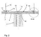
- the partition wall 7 is secured to the fixation panels 8a, 8b, 8c by insertion of fasteners 11 in the form of self-tapping screws through said ceiling panel and the fixation panels 8a, 8b, 8c.
- the partition wall 7 may be provided with a removable upper bracket 18 through which the self-tapping screws may be mounted.
- the bracket 18 may be mounted on the partition wall, for instance by means of screws, after mounting of said self-tapping screws. Other types of bracket may enable mounting of the bracket on the partition wall before mounting of the screws.
- the fixation panels are typically of a material that is harder than the material of the ceiling panels and are also typically of a material that is more rigid than the material of the ceiling panels. Consequently, the self-tapping screws will typically get a better grip in the fixation panels than in the ceiling panels.
- the partition wall 7 may also be secured to the fixation panels 8a, 8b, 8c by other types of fastener than screws, such as clamping devices, special rivets or the like.
- construction element has been illustrated above in the form of a partition wall, it could also for instance be a lamp or a projector.
- ceiling panels will not be able to carry such an element, and without the fixation panel, the position of the element would be restricted to the position of the runners.
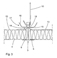
- Fig. 3 illustrates in greater detail an embodiment of the connection between the fixation panels 8 and the runners 3 of the supporting structure, whereby the fixation panels are adapted to snap-on connection to the runners.
- the fixation panels 8 are formed from a relatively thin plate material and each comprises a panel body 13 having opposed edges that are bent to form elastically deformable flanges 14 engaging the runners 3.
- Each elastically deformable flange 14 has a protrusion 15 engaging under a shoulder 16 of a runner 3 and a gripping part 17 spaced above the panel body 13, so that the protrusion 15 may be brought out of engagement with the shoulder 16 by pressing the gripping part 17 in the direction of the panel body 13.
- the gripping part 17 may advantageously have an end portion 18 that points in a direction upward and towards the centre of the panel body 13, whereby gripping of the gripping part 17 may be facilitated.
- the panel body 13 of the fixation panel 8 may be provided with not shown strengthening ribs.
- connection between the fixation panels 8 and the runners 3 of the supporting structure may for instance be carried out by means of spring-biased taps, a number of resilient flaps, sliders, or even screw connections or the like.
- the fixation panel can be particularly simple, such as a flat panel with no special engagement means for fixing to the runners of the grid.
- the partition wall may be mounted to the fixation panels 8 located above the ceiling panels 4 by means of screws inserted through some of the small bores in the ceiling panels. Thereby, the partition wall or other construction element may be removed again substantially without leaving any traces on the ceiling panels.
- the fixation panels may be provided with screw holes at positions corresponding to some of the small bores in the ceiling panels, thereby enabling the screw connection without having to drill holes in the fixation panels on the construction site.
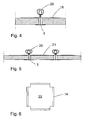
- Fig. 4 illustrates another embodiment of the suspended ceiling structure 1 according to the invention.
- a fixation panel 19 is connected to only one runner 3 of a supporting structure by means of an elastic bent portion 20 formed in the centre of the fixation panel 19 and gripping over a part of the runner 3.
- a construction element, such as a partition wall, may be connected to the fixation panel 19 as explained above.
- Fig. 5 shows a further development of the embodiment shown in Fig. 4 .
- one fixation panel 21 is formed with two spaced elastic bent portions 20, each gripping over a runner 3.
- a fixation panel could also have the form of one long element comprising several spaced elastic bent portions 20 or other connection means.
- Such a long standardized element could be shortened off to the desired length by breaking off a part of it, possibly at weakened lines made for this purpose.
- the fixation panels may abut the top side of the ceiling panels, this is generally not a requirement.
- a long fixation panel could be connected to only some of the runners it crosses, for instance by being placed above the runners.
- Fig. 6 shows another embodiment of the fixation panel.
- the fixation panel 22 is at each of its four sides provided with elastically deformable flanges 14 adapted to engage runners.
- the fixation panel may be made of a suitable material. In some applications it may be advantageous to choose a non-combustible material, such as metal, in view of fire regulations.
- the fixation panel may be adopted for easy gripping of a screw, such as by providing the face of the panel with a nubbly surface, indentations or perforations.
Landscapes
- Engineering & Computer Science (AREA)
- Architecture (AREA)
- Physics & Mathematics (AREA)
- Electromagnetism (AREA)
- Civil Engineering (AREA)
- Structural Engineering (AREA)
- Residential Or Office Buildings (AREA)
- Finishing Walls (AREA)
- Vehicle Interior And Exterior Ornaments, Soundproofing, And Insulation (AREA)
Claims (9)
- System, das eine abgehängte Deckenstruktur (1) umfasst, die mit einem Bauelement (7), wie etwa einer Trennwand oder einer Trockenbauwand, verbunden ist, wobei die abgehängte Deckenstruktur (1) eine tragende Struktur (2), die aus Schienen (3) zusammengesetzt ist, und eine Anzahl von Deckenplatten (4), die an Rändern (5) von der tragenden Struktur (2) getragen werden, umfasst, dadurch gekennzeichnet, dass wenigstens eine Fixierungsplatte (8a, 8b, 8c, 19, 21, 22) oberhalb einer Deckenplatte (4) montiert ist und an wenigstens einer Schiene (3) der tragenden Struktur (2) befestigt ist und dass das Bauelement (7) mittels Befestigern (11), die sich durch die Deckenplatte erstrecken, an der Fixierungsplatte befestigt ist.
- System, das eine abgehängte Deckenstruktur gemäß Anspruch 1 umfasst, dadurch gekennzeichnet, dass die Fixierungsplatte (8, 21, 22) an benachbarten Schienen (3) der tragenden Struktur (2) befestigt ist.
- System, das eine abgehängte Deckenstruktur gemäß Anspruch 1 oder 2 umfasst, dadurch gekennzeichnet, dass die Fixierungsplatte (8a, 8b, 8c, 19, 21, 22) für eine Rastverbindung mit den Schienen (3) der tragenden Struktur (2) angepasst ist.
- System, das eine abgehängte Deckenstruktur gemäß einem der vorhergehenden Ansprüche umfasst, dadurch gekennzeichnet, dass die Fixierungsplatte (8a, 8b, 8c, 19, 21, 22) aus einem relativ dünnen Plattenmaterial gebildet ist und einen Plattenkörper (13) mit gegenüberliegenden Rändern aufweist, die gebogen sind, um elastisch verformbare Flansche (14) zu bilden, die mit Schienen (3) der tragenden Struktur (2) in Eingriff stehen.
- System, das eine abgehängte Deckenstruktur gemäß Anspruch 4 umfasst, dadurch gekennzeichnet, dass jeder elastisch verformbare Flansch (14) einen Vorsprung (15), der unter einem Absatz (16) einer Schiene (3) in Eingriff steht, und einen Greifteil (17) aufweist, der oberhalb des Plattenkörpers (13) beabstandet ist, so dass der Vorsprung (15) durch Drücken des Greifteils (17) in der Richtung des Plattenkörpers (13) aus dem Eingriff mit dem Absatz (16) gelöst werden kann.
- System, das eine abgehängte Deckenstruktur gemäß Anspruch 4 oder 5 umfasst, dadurch gekennzeichnet, dass der Plattenkörper (13) der Fixierungsplatte mit Verstärkungsrippen versehen ist.
- Verfahren zum Montieren eines Systems gemäß einem der vorhergehenden Ansprüche, wobei ein Bauelement (7), wie etwa eine Trennwand oder eine Trockenbauwand, an eine abgehängte Deckenstruktur (1) montiert wird, die eine tragende Struktur (2), welche aus Schienen (3) zusammengesetzt ist, und eine Anzahl von Deckenplatten (4), welche an Rändern (5) von der tragenden Struktur (2) getragen werden, umfasst, gekennzeichnet durch ein Montieren wenigstens einer Fixierungsplatte (8a, 8b, 8c, 19, 21, 22) oberhalb einer Deckenplatte (4) und ein Befestigen der Fixierungsplatte an wenigstens einer Schiene (3) der tragenden Struktur (2) und durch ein Befestigen des Bauelementes an der Fixierungsplatte durch Einführen von Befestigern (11) durch die Deckenplatte.
- Verfahren gemäß Anspruch 7, dadurch gekennzeichnet, dass eine Anzahl von Deckenplatten (4) aus der abgehängten Deckenstruktur (1) entfernt werden, wodurch Öffnungen (9) in der abgehängten Deckenstruktur bereitgestellt werden, wobei durch die Öffnungen jeweils eine Anzahl von Fixierungsplatten (8a, 8b, 8c, 19, 21, 22) angeordnet werden und oberhalb von Deckenplatten (4), die von der tragenden Struktur (2) getragen werden, montiert werden, und dass die entfernten Deckenplatten nach dem Montieren der Fixierungsplatten wieder in der abgehängten Deckenstruktur angeordnet werden.
- Verfahren gemäß Anspruch 7 oder 8, dadurch gekennzeichnet, dass das Bauelement (7) an der Fixierungsplatte (8a, 8b, 8c, 19, 21, 22) befestigt wird, indem Schraubenlöcher (12) gebohrt werden, die sich durch sowohl die Deckenplatten (4) als auch die Fixierungsplatten erstrecken, und das Bauelement danach mittels bevorzugt selbstschneidender Schrauben, die in die Schraubenlöcher geschraubt werden, an der Fixierungsplatte befestigt wird.
Priority Applications (4)
| Application Number | Priority Date | Filing Date | Title |
|---|---|---|---|
| PL08171214T PL2196590T5 (pl) | 2008-12-10 | 2008-12-10 | Konstrukcja sufitu podwieszanego połączona z elementem konstrukcyjnym oraz sposób montowania elementu konstrukcyjnego do konstrukcji sufitu podwieszanego |
| DK08171214.3T DK2196590T4 (da) | 2008-12-10 | 2008-12-10 | Ophængt loftsstruktur, der er forbundet med et konstruktionselement, og fremgangsmåde til montering af et konstruktionselement på en op-hængt loftsstruktur |
| AT08171214T ATE531866T1 (de) | 2008-12-10 | 2008-12-10 | Abgehängte deckenstruktur mit bauelementanschluss und verfahren zur montage des bauelements an der abgehängten deckenstruktur |
| EP08171214.3A EP2196590B2 (de) | 2008-12-10 | 2008-12-10 | Abgehängte Deckenstruktur mit Bauelementanschluss und Verfahren zur Montage des Bauelements an der abgehängten Deckenstruktur |
Applications Claiming Priority (1)
| Application Number | Priority Date | Filing Date | Title |
|---|---|---|---|
| EP08171214.3A EP2196590B2 (de) | 2008-12-10 | 2008-12-10 | Abgehängte Deckenstruktur mit Bauelementanschluss und Verfahren zur Montage des Bauelements an der abgehängten Deckenstruktur |
Publications (3)
| Publication Number | Publication Date |
|---|---|
| EP2196590A1 EP2196590A1 (de) | 2010-06-16 |
| EP2196590B1 true EP2196590B1 (de) | 2011-11-02 |
| EP2196590B2 EP2196590B2 (de) | 2014-07-30 |
Family
ID=40473393
Family Applications (1)
| Application Number | Title | Priority Date | Filing Date |
|---|---|---|---|
| EP08171214.3A Active EP2196590B2 (de) | 2008-12-10 | 2008-12-10 | Abgehängte Deckenstruktur mit Bauelementanschluss und Verfahren zur Montage des Bauelements an der abgehängten Deckenstruktur |
Country Status (4)
| Country | Link |
|---|---|
| EP (1) | EP2196590B2 (de) |
| AT (1) | ATE531866T1 (de) |
| DK (1) | DK2196590T4 (de) |
| PL (1) | PL2196590T5 (de) |
Families Citing this family (3)
| Publication number | Priority date | Publication date | Assignee | Title |
|---|---|---|---|---|
| PL398712A1 (pl) | 2012-04-03 | 2013-10-14 | Es-System Spólka Akcyjna | Element nosny sufitu podwieszanego i sufit podwieszany zawierajacy taki element |
| CN114704018A (zh) * | 2021-04-02 | 2022-07-05 | 上海亮荣建设(集团)有限公司 | 一种室内装修用预制管线吊顶板 |
| CN113445656A (zh) * | 2021-07-26 | 2021-09-28 | 苏州金螳螂建筑装饰股份有限公司 | 一种超长过道顶面吸音板与设备带集成设计结构 |
Family Cites Families (7)
| Publication number | Priority date | Publication date | Assignee | Title |
|---|---|---|---|---|
| US3685235A (en) * | 1970-09-21 | 1972-08-22 | Bajer Ind Inc | Suspended ceiling system including a grid network |
| US4209953A (en) * | 1977-08-15 | 1980-07-01 | United States Gypsum Company | Ceiling runner attachment system and clip therefor |
| SE455429B (sv) | 1986-11-03 | 1988-07-11 | Jernkonst Ab | Undertakskonstruktion |
| US4838002A (en) * | 1988-06-27 | 1989-06-13 | Dajnko Milan A | Clip fastener securable to ceiling T-bar to retain wall partition in position |
| EP0681070A1 (de) * | 1994-03-31 | 1995-11-08 | Clestra Hauserman | Abgehängte Decke |
| GB9827744D0 (en) | 1998-12-17 | 1999-02-10 | Parker Brian B | Partitioning |
| GB2407826B (en) * | 2003-10-13 | 2007-05-23 | Burgess Architectural Products | Ceiling grids |
-
2008
- 2008-12-10 AT AT08171214T patent/ATE531866T1/de active
- 2008-12-10 EP EP08171214.3A patent/EP2196590B2/de active Active
- 2008-12-10 DK DK08171214.3T patent/DK2196590T4/da active
- 2008-12-10 PL PL08171214T patent/PL2196590T5/pl unknown
Also Published As
| Publication number | Publication date |
|---|---|
| PL2196590T5 (pl) | 2014-10-31 |
| EP2196590B2 (de) | 2014-07-30 |
| EP2196590A1 (de) | 2010-06-16 |
| DK2196590T4 (da) | 2014-09-08 |
| PL2196590T3 (pl) | 2012-04-30 |
| ATE531866T1 (de) | 2011-11-15 |
| DK2196590T3 (da) | 2012-02-20 |
Similar Documents
| Publication | Publication Date | Title |
|---|---|---|
| US5338255A (en) | Air duct fitting mounting shoulder | |
| US10288269B2 (en) | Ceiling system | |
| KR20150101855A (ko) | 천정 마감용 패널 및 이를 구비한 천정 마감장치 | |
| EP2196590B1 (de) | Abgehängte Deckenstruktur mit Bauelementanschluss und Verfahren zur Montage des Bauelements an der abgehängten Deckenstruktur | |
| US20060101744A1 (en) | Ceiling and wall panel clips | |
| EP0577661B1 (de) | Rahmenstruktur für eine querwand | |
| US4257205A (en) | Attachment system for suspended drywall ceiling panels | |
| WO2023053832A1 (ja) | パネル装置 | |
| US20240299788A1 (en) | Side bracket for installation of sprinkler | |
| JP2024142730A (ja) | ルーバー材及びシステム天井 | |
| JP4822627B2 (ja) | 天井板固定枠を使用した天井構造 | |
| JP3079453B2 (ja) | 天井バー用連結金具 | |
| JP5289924B2 (ja) | 設備用下地材固定金物及びこれを備えたパネル | |
| EP1775398B1 (de) | Deckensystemverbinder | |
| JP7788656B2 (ja) | パネル装置 | |
| AU2017101778B4 (en) | A firestopping device and associated method | |
| JP7777790B2 (ja) | パネル装置及びこれの設置構造 | |
| JP7777788B2 (ja) | パネル設置構造 | |
| JP7365209B2 (ja) | 天井部材取り付け具、建物天井及びその施工方法 | |
| JP7777791B2 (ja) | パネル装置 | |
| JP7777789B2 (ja) | パネル装置 | |
| GB2082222A (en) | Clip for connecting rails for a suspended ceiling | |
| KR100470679B1 (ko) | 욕실용 천장 패널과 그 시공방법 | |
| WO2023054014A1 (ja) | パネル装置及びこれの設置構造 | |
| WO2023054015A1 (ja) | パネル設置構造 |
Legal Events
| Date | Code | Title | Description |
|---|---|---|---|
| PUAI | Public reference made under article 153(3) epc to a published international application that has entered the european phase |
Free format text: ORIGINAL CODE: 0009012 |
|
| AK | Designated contracting states |
Kind code of ref document: A1 Designated state(s): AT BE BG CH CY CZ DE DK EE ES FI FR GB GR HR HU IE IS IT LI LT LU LV MC MT NL NO PL PT RO SE SI SK TR |
|
| AX | Request for extension of the european patent |
Extension state: AL BA MK RS |
|
| 17P | Request for examination filed |
Effective date: 20101216 |
|
| AKX | Designation fees paid |
Designated state(s): AT BE BG CH CY CZ DE DK EE ES FI FR GB GR HR HU IE IS IT LI LT LU LV MC MT NL NO PL PT RO SE SI SK TR |
|
| GRAP | Despatch of communication of intention to grant a patent |
Free format text: ORIGINAL CODE: EPIDOSNIGR1 |
|
| GRAS | Grant fee paid |
Free format text: ORIGINAL CODE: EPIDOSNIGR3 |
|
| GRAA | (expected) grant |
Free format text: ORIGINAL CODE: 0009210 |
|
| AK | Designated contracting states |
Kind code of ref document: B1 Designated state(s): AT BE BG CH CY CZ DE DK EE ES FI FR GB GR HR HU IE IS IT LI LT LU LV MC MT NL NO PL PT RO SE SI SK TR |
|
| REG | Reference to a national code |
Ref country code: GB Ref legal event code: FG4D |
|
| REG | Reference to a national code |
Ref country code: CH Ref legal event code: EP |
|
| REG | Reference to a national code |
Ref country code: IE Ref legal event code: FG4D |
|
| REG | Reference to a national code |
Ref country code: DE Ref legal event code: R096 Ref document number: 602008011044 Country of ref document: DE Effective date: 20120105 |
|
| REG | Reference to a national code |
Ref country code: NL Ref legal event code: T3 |
|
| REG | Reference to a national code |
Ref country code: DK Ref legal event code: T3 |
|
| REG | Reference to a national code |
Ref country code: SE Ref legal event code: TRGR |
|
| REG | Reference to a national code |
Ref country code: NO Ref legal event code: T2 Effective date: 20111102 |
|
| LTIE | Lt: invalidation of european patent or patent extension |
Effective date: 20111102 |
|
| PG25 | Lapsed in a contracting state [announced via postgrant information from national office to epo] |
Ref country code: LT Free format text: LAPSE BECAUSE OF FAILURE TO SUBMIT A TRANSLATION OF THE DESCRIPTION OR TO PAY THE FEE WITHIN THE PRESCRIBED TIME-LIMIT Effective date: 20111102 Ref country code: IS Free format text: LAPSE BECAUSE OF FAILURE TO SUBMIT A TRANSLATION OF THE DESCRIPTION OR TO PAY THE FEE WITHIN THE PRESCRIBED TIME-LIMIT Effective date: 20120302 |
|
| REG | Reference to a national code |
Ref country code: PL Ref legal event code: T3 |
|
| PG25 | Lapsed in a contracting state [announced via postgrant information from national office to epo] |
Ref country code: GR Free format text: LAPSE BECAUSE OF FAILURE TO SUBMIT A TRANSLATION OF THE DESCRIPTION OR TO PAY THE FEE WITHIN THE PRESCRIBED TIME-LIMIT Effective date: 20120203 Ref country code: HR Free format text: LAPSE BECAUSE OF FAILURE TO SUBMIT A TRANSLATION OF THE DESCRIPTION OR TO PAY THE FEE WITHIN THE PRESCRIBED TIME-LIMIT Effective date: 20111102 Ref country code: LV Free format text: LAPSE BECAUSE OF FAILURE TO SUBMIT A TRANSLATION OF THE DESCRIPTION OR TO PAY THE FEE WITHIN THE PRESCRIBED TIME-LIMIT Effective date: 20111102 Ref country code: SI Free format text: LAPSE BECAUSE OF FAILURE TO SUBMIT A TRANSLATION OF THE DESCRIPTION OR TO PAY THE FEE WITHIN THE PRESCRIBED TIME-LIMIT Effective date: 20111102 Ref country code: PT Free format text: LAPSE BECAUSE OF FAILURE TO SUBMIT A TRANSLATION OF THE DESCRIPTION OR TO PAY THE FEE WITHIN THE PRESCRIBED TIME-LIMIT Effective date: 20120302 |
|
| PG25 | Lapsed in a contracting state [announced via postgrant information from national office to epo] |
Ref country code: CY Free format text: LAPSE BECAUSE OF FAILURE TO SUBMIT A TRANSLATION OF THE DESCRIPTION OR TO PAY THE FEE WITHIN THE PRESCRIBED TIME-LIMIT Effective date: 20111102 |
|
| PG25 | Lapsed in a contracting state [announced via postgrant information from national office to epo] |
Ref country code: CZ Free format text: LAPSE BECAUSE OF FAILURE TO SUBMIT A TRANSLATION OF THE DESCRIPTION OR TO PAY THE FEE WITHIN THE PRESCRIBED TIME-LIMIT Effective date: 20111102 Ref country code: MC Free format text: LAPSE BECAUSE OF NON-PAYMENT OF DUE FEES Effective date: 20111231 Ref country code: SK Free format text: LAPSE BECAUSE OF FAILURE TO SUBMIT A TRANSLATION OF THE DESCRIPTION OR TO PAY THE FEE WITHIN THE PRESCRIBED TIME-LIMIT Effective date: 20111102 Ref country code: EE Free format text: LAPSE BECAUSE OF FAILURE TO SUBMIT A TRANSLATION OF THE DESCRIPTION OR TO PAY THE FEE WITHIN THE PRESCRIBED TIME-LIMIT Effective date: 20111102 Ref country code: BG Free format text: LAPSE BECAUSE OF FAILURE TO SUBMIT A TRANSLATION OF THE DESCRIPTION OR TO PAY THE FEE WITHIN THE PRESCRIBED TIME-LIMIT Effective date: 20120202 |
|
| PLBI | Opposition filed |
Free format text: ORIGINAL CODE: 0009260 |
|
| PG25 | Lapsed in a contracting state [announced via postgrant information from national office to epo] |
Ref country code: RO Free format text: LAPSE BECAUSE OF FAILURE TO SUBMIT A TRANSLATION OF THE DESCRIPTION OR TO PAY THE FEE WITHIN THE PRESCRIBED TIME-LIMIT Effective date: 20111102 |
|
| 26 | Opposition filed |
Opponent name: SAINT-GOBAIN ECOPHON AB Effective date: 20120731 |
|
| PLAX | Notice of opposition and request to file observation + time limit sent |
Free format text: ORIGINAL CODE: EPIDOSNOBS2 |
|
| REG | Reference to a national code |
Ref country code: IE Ref legal event code: MM4A |
|
| REG | Reference to a national code |
Ref country code: DE Ref legal event code: R026 Ref document number: 602008011044 Country of ref document: DE Effective date: 20120731 |
|
| PG25 | Lapsed in a contracting state [announced via postgrant information from national office to epo] |
Ref country code: IE Free format text: LAPSE BECAUSE OF NON-PAYMENT OF DUE FEES Effective date: 20111210 |
|
| PLAF | Information modified related to communication of a notice of opposition and request to file observations + time limit |
Free format text: ORIGINAL CODE: EPIDOSCOBS2 |
|
| PG25 | Lapsed in a contracting state [announced via postgrant information from national office to epo] |
Ref country code: MT Free format text: LAPSE BECAUSE OF FAILURE TO SUBMIT A TRANSLATION OF THE DESCRIPTION OR TO PAY THE FEE WITHIN THE PRESCRIBED TIME-LIMIT Effective date: 20111102 |
|
| PLBB | Reply of patent proprietor to notice(s) of opposition received |
Free format text: ORIGINAL CODE: EPIDOSNOBS3 |
|
| PG25 | Lapsed in a contracting state [announced via postgrant information from national office to epo] |
Ref country code: LU Free format text: LAPSE BECAUSE OF NON-PAYMENT OF DUE FEES Effective date: 20111210 |
|
| PG25 | Lapsed in a contracting state [announced via postgrant information from national office to epo] |
Ref country code: FI Free format text: LAPSE BECAUSE OF FAILURE TO SUBMIT A TRANSLATION OF THE DESCRIPTION OR TO PAY THE FEE WITHIN THE PRESCRIBED TIME-LIMIT Effective date: 20111102 |
|
| REG | Reference to a national code |
Ref country code: CH Ref legal event code: PL |
|
| PG25 | Lapsed in a contracting state [announced via postgrant information from national office to epo] |
Ref country code: TR Free format text: LAPSE BECAUSE OF FAILURE TO SUBMIT A TRANSLATION OF THE DESCRIPTION OR TO PAY THE FEE WITHIN THE PRESCRIBED TIME-LIMIT Effective date: 20111102 |
|
| PG25 | Lapsed in a contracting state [announced via postgrant information from national office to epo] |
Ref country code: LI Free format text: LAPSE BECAUSE OF NON-PAYMENT OF DUE FEES Effective date: 20121231 Ref country code: CH Free format text: LAPSE BECAUSE OF NON-PAYMENT OF DUE FEES Effective date: 20121231 Ref country code: ES Free format text: LAPSE BECAUSE OF FAILURE TO SUBMIT A TRANSLATION OF THE DESCRIPTION OR TO PAY THE FEE WITHIN THE PRESCRIBED TIME-LIMIT Effective date: 20120213 Ref country code: HU Free format text: LAPSE BECAUSE OF FAILURE TO SUBMIT A TRANSLATION OF THE DESCRIPTION OR TO PAY THE FEE WITHIN THE PRESCRIBED TIME-LIMIT Effective date: 20111102 |
|
| PGFP | Annual fee paid to national office [announced via postgrant information from national office to epo] |
Ref country code: AT Payment date: 20131126 Year of fee payment: 6 Ref country code: GB Payment date: 20131204 Year of fee payment: 6 |
|
| PGFP | Annual fee paid to national office [announced via postgrant information from national office to epo] |
Ref country code: IT Payment date: 20131213 Year of fee payment: 6 |
|
| PUAH | Patent maintained in amended form |
Free format text: ORIGINAL CODE: 0009272 |
|
| STAA | Information on the status of an ep patent application or granted ep patent |
Free format text: STATUS: PATENT MAINTAINED AS AMENDED |
|
| 27A | Patent maintained in amended form |
Effective date: 20140730 |
|
| AK | Designated contracting states |
Kind code of ref document: B2 Designated state(s): AT BE BG CH CY CZ DE DK EE ES FI FR GB GR HR HU IE IS IT LI LT LU LV MC MT NL NO PL PT RO SE SI SK TR |
|
| REG | Reference to a national code |
Ref country code: DE Ref legal event code: R102 Ref document number: 602008011044 Country of ref document: DE |
|
| REG | Reference to a national code |
Ref country code: DE Ref legal event code: R102 Ref document number: 602008011044 Country of ref document: DE Effective date: 20140730 |
|
| REG | Reference to a national code |
Ref country code: DK Ref legal event code: T4 Effective date: 20140903 |
|
| REG | Reference to a national code |
Ref country code: SE Ref legal event code: RPEO |
|
| REG | Reference to a national code |
Ref country code: NO Ref legal event code: T2 Effective date: 20111102 Ref country code: NO Ref legal event code: T3 |
|
| REG | Reference to a national code |
Ref country code: PL Ref legal event code: T5 |
|
| REG | Reference to a national code |
Ref country code: NL Ref legal event code: T3 |
|
| PGFP | Annual fee paid to national office [announced via postgrant information from national office to epo] |
Ref country code: DE Payment date: 20141202 Year of fee payment: 7 |
|
| PG25 | Lapsed in a contracting state [announced via postgrant information from national office to epo] |
Ref country code: LV Free format text: LAPSE BECAUSE OF FAILURE TO SUBMIT A TRANSLATION OF THE DESCRIPTION OR TO PAY THE FEE WITHIN THE PRESCRIBED TIME-LIMIT Effective date: 20140730 |
|
| REG | Reference to a national code |
Ref country code: AT Ref legal event code: MM01 Ref document number: 531866 Country of ref document: AT Kind code of ref document: T Effective date: 20141210 |
|
| GBPC | Gb: european patent ceased through non-payment of renewal fee |
Effective date: 20141210 |
|
| PG25 | Lapsed in a contracting state [announced via postgrant information from national office to epo] |
Ref country code: GB Free format text: LAPSE BECAUSE OF NON-PAYMENT OF DUE FEES Effective date: 20141210 |
|
| REG | Reference to a national code |
Ref country code: FR Ref legal event code: PLFP Year of fee payment: 8 |
|
| PG25 | Lapsed in a contracting state [announced via postgrant information from national office to epo] |
Ref country code: AT Free format text: LAPSE BECAUSE OF NON-PAYMENT OF DUE FEES Effective date: 20141210 |
|
| PG25 | Lapsed in a contracting state [announced via postgrant information from national office to epo] |
Ref country code: IT Free format text: LAPSE BECAUSE OF NON-PAYMENT OF DUE FEES Effective date: 20141210 |
|
| REG | Reference to a national code |
Ref country code: DE Ref legal event code: R119 Ref document number: 602008011044 Country of ref document: DE |
|
| PG25 | Lapsed in a contracting state [announced via postgrant information from national office to epo] |
Ref country code: DE Free format text: LAPSE BECAUSE OF NON-PAYMENT OF DUE FEES Effective date: 20160701 |
|
| REG | Reference to a national code |
Ref country code: FR Ref legal event code: PLFP Year of fee payment: 9 |
|
| REG | Reference to a national code |
Ref country code: FR Ref legal event code: PLFP Year of fee payment: 10 |
|
| REG | Reference to a national code |
Ref country code: NO Ref legal event code: CHAD Owner name: ROCKWOOL A/S, DK |
|
| REG | Reference to a national code |
Ref country code: NL Ref legal event code: HC Owner name: ROCKWOOL A/S; DK Free format text: DETAILS ASSIGNMENT: CHANGE OF OWNER(S), CHANGE OF OWNER(S) NAME; FORMER OWNER NAME: ROCKWOOL INTERNATIONAL A/S Effective date: 20230728 |
|
| REG | Reference to a national code |
Ref country code: BE Ref legal event code: PD Owner name: ROCKWOOL INTERNATIONAL A/S; DK Free format text: DETAILS ASSIGNMENT: CHANGE OF OWNER(S), OTHER; FORMER OWNER NAME: ROCKWOOL INTERNATIONAL A/S Effective date: 20241212 Ref country code: BE Ref legal event code: HC Owner name: ROCKWOOL A/S; DK Free format text: DETAILS ASSIGNMENT: CHANGE OF OWNER(S), CHANGE OF OWNER(S) NAME; FORMER OWNER NAME: ROCKWOOL INTERNATIONAL A/S Effective date: 20241212 |
|
| PGFP | Annual fee paid to national office [announced via postgrant information from national office to epo] |
Ref country code: NO Payment date: 20251231 Year of fee payment: 18 |
|
| PGFP | Annual fee paid to national office [announced via postgrant information from national office to epo] |
Ref country code: DK Payment date: 20251226 Year of fee payment: 18 |
|
| PGFP | Annual fee paid to national office [announced via postgrant information from national office to epo] |
Ref country code: NL Payment date: 20251226 Year of fee payment: 18 Ref country code: FR Payment date: 20251226 Year of fee payment: 18 |
|
| PGFP | Annual fee paid to national office [announced via postgrant information from national office to epo] |
Ref country code: BE Payment date: 20251229 Year of fee payment: 18 |
|
| PGFP | Annual fee paid to national office [announced via postgrant information from national office to epo] |
Ref country code: SE Payment date: 20251227 Year of fee payment: 18 |
|
| PGFP | Annual fee paid to national office [announced via postgrant information from national office to epo] |
Ref country code: PL Payment date: 20251119 Year of fee payment: 18 |