EP2196594A1 - Elément de revêtement de bâtiments - Google Patents
Elément de revêtement de bâtiments Download PDFInfo
- Publication number
- EP2196594A1 EP2196594A1 EP09178519A EP09178519A EP2196594A1 EP 2196594 A1 EP2196594 A1 EP 2196594A1 EP 09178519 A EP09178519 A EP 09178519A EP 09178519 A EP09178519 A EP 09178519A EP 2196594 A1 EP2196594 A1 EP 2196594A1
- Authority
- EP
- European Patent Office
- Prior art keywords
- frame
- component
- panel
- profile
- components
- Prior art date
- Legal status (The legal status is an assumption and is not a legal conclusion. Google has not performed a legal analysis and makes no representation as to the accuracy of the status listed.)
- Granted
Links
Images



Classifications
-
- E—FIXED CONSTRUCTIONS
- E04—BUILDING
- E04D—ROOF COVERINGS; SKY-LIGHTS; GUTTERS; ROOF-WORKING TOOLS
- E04D3/00—Roof covering by making use of flat or curved slabs or stiff sheets
- E04D3/02—Roof covering by making use of flat or curved slabs or stiff sheets of plane slabs, slates, or sheets, or in which the cross-section is unimportant
-
- F—MECHANICAL ENGINEERING; LIGHTING; HEATING; WEAPONS; BLASTING
- F24—HEATING; RANGES; VENTILATING
- F24S—SOLAR HEAT COLLECTORS; SOLAR HEAT SYSTEMS
- F24S20/00—Solar heat collectors specially adapted for particular uses or environments
- F24S20/60—Solar heat collectors integrated in fixed constructions, e.g. in buildings
- F24S20/67—Solar heat collectors integrated in fixed constructions, e.g. in buildings in the form of roof constructions
-
- F—MECHANICAL ENGINEERING; LIGHTING; HEATING; WEAPONS; BLASTING
- F24—HEATING; RANGES; VENTILATING
- F24S—SOLAR HEAT COLLECTORS; SOLAR HEAT SYSTEMS
- F24S25/00—Arrangement of stationary mountings or supports for solar heat collector modules
- F24S25/20—Peripheral frames for modules
-
- F—MECHANICAL ENGINEERING; LIGHTING; HEATING; WEAPONS; BLASTING
- F24—HEATING; RANGES; VENTILATING
- F24S—SOLAR HEAT COLLECTORS; SOLAR HEAT SYSTEMS
- F24S40/00—Safety or protection arrangements of solar heat collectors; Preventing malfunction of solar heat collectors
- F24S40/40—Preventing corrosion; Protecting against dirt or contamination
- F24S40/44—Draining rainwater or condensation
-
- H—ELECTRICITY
- H02—GENERATION; CONVERSION OR DISTRIBUTION OF ELECTRIC POWER
- H02S—GENERATION OF ELECTRIC POWER BY CONVERSION OF INFRARED RADIATION, VISIBLE LIGHT OR ULTRAVIOLET LIGHT, e.g. USING PHOTOVOLTAIC [PV] MODULES
- H02S20/00—Supporting structures for PV modules
- H02S20/20—Supporting structures directly fixed to an immovable object
- H02S20/22—Supporting structures directly fixed to an immovable object specially adapted for buildings
- H02S20/23—Supporting structures directly fixed to an immovable object specially adapted for buildings specially adapted for roof structures
-
- F—MECHANICAL ENGINEERING; LIGHTING; HEATING; WEAPONS; BLASTING
- F24—HEATING; RANGES; VENTILATING
- F24S—SOLAR HEAT COLLECTORS; SOLAR HEAT SYSTEMS
- F24S20/00—Solar heat collectors specially adapted for particular uses or environments
- F24S2020/10—Solar modules layout; Modular arrangements
- F24S2020/13—Overlaying arrangements similar to roof tiles
-
- F—MECHANICAL ENGINEERING; LIGHTING; HEATING; WEAPONS; BLASTING
- F24—HEATING; RANGES; VENTILATING
- F24S—SOLAR HEAT COLLECTORS; SOLAR HEAT SYSTEMS
- F24S25/00—Arrangement of stationary mountings or supports for solar heat collector modules
- F24S2025/01—Special support components; Methods of use
- F24S2025/014—Methods for installing support elements
-
- F—MECHANICAL ENGINEERING; LIGHTING; HEATING; WEAPONS; BLASTING
- F24—HEATING; RANGES; VENTILATING
- F24S—SOLAR HEAT COLLECTORS; SOLAR HEAT SYSTEMS
- F24S25/00—Arrangement of stationary mountings or supports for solar heat collector modules
- F24S2025/01—Special support components; Methods of use
- F24S2025/015—Supports with play between elements
-
- Y—GENERAL TAGGING OF NEW TECHNOLOGICAL DEVELOPMENTS; GENERAL TAGGING OF CROSS-SECTIONAL TECHNOLOGIES SPANNING OVER SEVERAL SECTIONS OF THE IPC; TECHNICAL SUBJECTS COVERED BY FORMER USPC CROSS-REFERENCE ART COLLECTIONS [XRACs] AND DIGESTS
- Y02—TECHNOLOGIES OR APPLICATIONS FOR MITIGATION OR ADAPTATION AGAINST CLIMATE CHANGE
- Y02B—CLIMATE CHANGE MITIGATION TECHNOLOGIES RELATED TO BUILDINGS, e.g. HOUSING, HOUSE APPLIANCES OR RELATED END-USER APPLICATIONS
- Y02B10/00—Integration of renewable energy sources in buildings
- Y02B10/10—Photovoltaic [PV]
-
- Y—GENERAL TAGGING OF NEW TECHNOLOGICAL DEVELOPMENTS; GENERAL TAGGING OF CROSS-SECTIONAL TECHNOLOGIES SPANNING OVER SEVERAL SECTIONS OF THE IPC; TECHNICAL SUBJECTS COVERED BY FORMER USPC CROSS-REFERENCE ART COLLECTIONS [XRACs] AND DIGESTS
- Y02—TECHNOLOGIES OR APPLICATIONS FOR MITIGATION OR ADAPTATION AGAINST CLIMATE CHANGE
- Y02B—CLIMATE CHANGE MITIGATION TECHNOLOGIES RELATED TO BUILDINGS, e.g. HOUSING, HOUSE APPLIANCES OR RELATED END-USER APPLICATIONS
- Y02B10/00—Integration of renewable energy sources in buildings
- Y02B10/20—Solar thermal
-
- Y—GENERAL TAGGING OF NEW TECHNOLOGICAL DEVELOPMENTS; GENERAL TAGGING OF CROSS-SECTIONAL TECHNOLOGIES SPANNING OVER SEVERAL SECTIONS OF THE IPC; TECHNICAL SUBJECTS COVERED BY FORMER USPC CROSS-REFERENCE ART COLLECTIONS [XRACs] AND DIGESTS
- Y02—TECHNOLOGIES OR APPLICATIONS FOR MITIGATION OR ADAPTATION AGAINST CLIMATE CHANGE
- Y02E—REDUCTION OF GREENHOUSE GAS [GHG] EMISSIONS, RELATED TO ENERGY GENERATION, TRANSMISSION OR DISTRIBUTION
- Y02E10/00—Energy generation through renewable energy sources
- Y02E10/40—Solar thermal energy, e.g. solar towers
- Y02E10/47—Mountings or tracking
-
- Y—GENERAL TAGGING OF NEW TECHNOLOGICAL DEVELOPMENTS; GENERAL TAGGING OF CROSS-SECTIONAL TECHNOLOGIES SPANNING OVER SEVERAL SECTIONS OF THE IPC; TECHNICAL SUBJECTS COVERED BY FORMER USPC CROSS-REFERENCE ART COLLECTIONS [XRACs] AND DIGESTS
- Y02—TECHNOLOGIES OR APPLICATIONS FOR MITIGATION OR ADAPTATION AGAINST CLIMATE CHANGE
- Y02E—REDUCTION OF GREENHOUSE GAS [GHG] EMISSIONS, RELATED TO ENERGY GENERATION, TRANSMISSION OR DISTRIBUTION
- Y02E10/00—Energy generation through renewable energy sources
- Y02E10/50—Photovoltaic [PV] energy
Definitions
- the invention relates to a component for covering buildings, in particular pitched roofs or facades, according to the preamble of the independent claim.
- roofs or facades of buildings are to be equipped with photovoltaic modules, they can be mounted on an existing façade or an existing roof, i. they are mounted on the façade or the roof with a suitable, usually complicated assembly construction.
- the existing roof skin such as a tile roof, can continue to be used and the photovoltaic modules do not have to perform a sealing function.
- the assembly structure must be individually adapted to a particular roof. In terms of cost, this method is particularly advantageous for existing roofs and facades.
- appropriately designed photovoltaic modules themselves form the dense lining of the roof or the facade. This option is particularly advantageous for new buildings or larger renovations, since the cost of covering the roof can be partially saved and thus the total construction costs can be reduced. Another advantage of such a solution is a more uniform optical appearance, and thus an aesthetically pleasing effect.
- FR 2465315 shows a photovoltaic module, which are fitted in a metal profile frame, so that there is a plate-shaped photovoltaic device.
- the photovoltaic module is sealed in a circumferential profile of the frame.
- the profile frame is designed such that the components such as brick can be installed in a scaly overlapping manner.
- the profile frame adjacent components interlock, so that there is a rainproof roof skin.
- the photovoltaic devices are fixed like conventional bricks with brackets on the roof battens. The construction as a small brick is disadvantageous for use as a photovoltaic module for electrical reasons.
- EP 1060520 shows a photovoltaic device, which corresponds in size to conventional photovoltaic modules, and therefore much larger than conventional bricks.
- the illustrated photovoltaic device has laterally a profile frame, which engages in the profile frame of the adjacent component, and thus creates a rain-tight connection.
- the overhead profile has a horizontal drainage channel, and means for attaching the device to the roof structure. On the bottom side, the profile is designed to only support the photovoltaic module but not cover it on top of the light receiving top.
- EP 1703037 shows a photovoltaic device, in which on the building side facing the component supporting devices are arranged, which cooperate with support elements which are mounted on a substructure, such as the roof battens.
- a construction with side frame profiles that interlock has the advantage that in the fall direction the profile below forms a drainage channel through which the rainwater can flow.
- this design has the disadvantage that the laying of the individual components must necessarily be made in a certain horizontal and vertical order. In the maintenance or repair of individual components, this can lead to problems.
- EP 1362967 shows a system in which each between two rows of adjacent components in the direction of fall a continuous, upwardly open rail is arranged.
- the side frame profiles engage in this rail, so that forms a continuous drainage channel and at the same time a rain-tight lateral connection between the components in the direction of fall. Individual components are so accessible, without the laterally adjacent components are affected.
- An object of the invention is to provide a device of the type mentioned, in particular a photovoltaic device, which does not have the above-mentioned and other disadvantages.
- Another object of the invention is to provide a component which makes it possible to cover a pitched roof or a facade from top to bottom.
- Another object of the invention is to provide a component which makes it possible to replace individual components in a finished building cladding without having to remove other components.
- Yet another object of the invention is to provide a component that does not require additional, separate plastic sealing elements.
- Another object of the invention is to provide components with which roofs and facades can be covered rainproof, with the least possible material consumption.
- a device according to the invention should also be inexpensive to produce in smaller series.
- a component according to the invention is provided for the rain-proof cladding of a building exterior, in particular a pitched roof or a facade, with a plurality of overlapping components.
- the component comprises a frame and a panel fixed in or on this frame.
- the frame has an upper profile with two or more sealing lips projecting towards the outer weather side and a lower profile with two or more sealing lips projecting inwards away from the weather side.
- the upper or lower profiles are designed such that they can be brought into engagement with a lower or upper profile of an adjacent structurally identical component, resulting in a labyrinth seal.
- Rainproof means in this context of the invention described not absolutely waterproof, but tight against the ingress of water due to external weather conditions, especially rain.
- the lower and upper profiles of directly adjacent components do not come into contact with each other. Instead, they have a certain amount of play, so that, given a thermal expansion of the components, no mechanical stresses can build up due to a temperature change. This is particularly important for components with photovoltaic panels, as they heat and cool very quickly due to the dark color, so that over the course of a day, a significant change in length can result.
- the panel is preferably kept sealed in the frame.
- Said panel may be a photovoltaic module, or a solar collector module for the production of hot water, or even a simple cover without additional function, such as sheet metal, glass, or transparent plastic.
- the labyrinth seal in which the sealing lips of the interlocking profiles are arranged alternately, prevents flowing in the direction of fall on the roof running water under the components. It also effectively prevents the ingress of mist or water spray, and captures condensation.
- the upper and the lower profile of the frame is designed such that the upper profile by a Pivoting movement along a pivot axis parallel to an upper edge of the component with a lower profile of an above the component mounted on a substructure identical component can be brought into engagement.
- components can be mounted in this way from above, from the ridge, down towards the eaves, with already assembled components must not be solved, moved or raised.
- An assembler can work from below the covered roof during installation, taking a comparatively comfortable posture and a secure footing. There is also a reduced risk of accidentally damaging already installed components.
- the frame of a component according to the invention has two lateral profiles, with two or more inwardly projecting sealing lips.
- the panel may be disposed in a U-shaped groove of the frame and / or on a mounting surface of the frame.
- the panel and the frame of the device form a substantially watertight surface.
- the upper profile has at least one horizontal gutter.
- the panel of a device according to the invention may be, for example, a photovoltaic module or a solar collector module.
- this component is constructed modularly from individual parts which can be combined as required.
- An inventive building cladding in particular for a pitched roof, has a plurality of such novel components.
- a slanted roof according to the invention and a building facade according to the invention have as or more components according to the invention.
- a power generation plant according to the invention in particular a photovoltaic plant or a solar collector plant, have one or more components according to the invention.
- a frame with a circumferential mounting surface is provided. Subsequently, a panel is placed on the mounting surface of the frame, and a seal is applied between an outer edge and the edge of the panel. The seal forms a watertight surface of the device with the frame and the panel.
- FIG. 1 An exemplary embodiment of a device 1 according to the invention is shown in FIG FIG. 1 shown.
- FIG. 3 shows the same component in an exploded view, with the panel omitted.
- a rectangular panel 12 is held on all four sides by a peripheral frame 11.
- the seal between frame and panel may be a silicone rubber seal or a circumferential sealing lip made of a suitable elastomer.
- the frame 11 consists essentially of four frame profiles 2, 2 ', 3, 4, which have a directed against the center U-shaped groove in which the panel is sealingly mounted.
- the frame profiles are preferably made Light metal manufactured by continuous casting. In order to form the frame, the profiles are preferably screwed together, being provided for this purpose in the illustrated embodiment access openings 24 for a tool. Alternatively, other fastening techniques are conceivable, for example soldering, gluing, welding or riveting.
- the structure of the frame of simple frame profiles in addition to reduced costs and the advantage that can be made by simply cutting the profiles very quickly the frame for a panel of any size.
- special dimensioning requirements can be taken into account without additional costs, and on the other hand purchased photovoltaic modules can be very easily installed in a component according to the invention.
- the corners of the device in the installed state are not visible, can be dispensed with complex corner finishes. Should the replacement of a component become necessary at a later date, but the corresponding frame profiles are no longer available, the component to be replaced can also be disassembled, the panel replaced, and the old frame profiles reassembled to form a new component.
- the dimensions of the comparatively small dimensioned component in FIG. 1 is to be understood only as an example. Modern photovoltaic panels have much larger dimensions, for example 80 cm X 160 cm.
- the two lateral profiles 2, 2 ' have a U-shaped groove for receiving the panel 12 and an inner 22 and an outer 21 sealing lip.
- the two profiles 2, 2 ' are identical, and differ only in their orientation with respect to the component.
- the side profiles run in the direction of fall.
- an upper profile 4 is arranged, with two directed to the outer side of the device sealing lips 41, 42.
- the outer located at the edge of the sealing lip 41 closes off a horizontal gutter 43, which later in the labyrinth seal Collects collected condensed water and water spray to the side.
- the lower profile 3 located at a lower end of the component has a cover 37, as well as two sealing lips 31 and 32 directed towards the inner side of the component.
- the outer, located at the edge sealing lip 41 may also be shorter than in the example shown, as long as it is ensured that the horizontal gutter 43 can absorb splash or condensation, which runs down on the sealing lip 32 '.
- water in the horizontal drainage channels 43, 43a, 39 on the side can flow off into the drainage channel 8 extending in the fall direction.
- openings in the lateral profile or at the longitudinal ends of the gutters 43, 43 a, 39 may be present, through which the collected water can flow into the drain channel 8.
- the lower profile 3 extends over the entire width of the component, while the upper profile 4 is flanked by the two lateral profiles 2, 2 '.
- the lower profile between the two lateral profiles run, or both 3, 4 profiles extend over the entire width.
- Other combinations are also conceivable, since the sealing effect is given in each case.
- FIG. 2 shows a longitudinal section in the direction of fall through the overlapping edge region of two completely assembled components 1, 1 'according to the invention.
- a support element 5 is arranged, which is fastened with one or more fastening means 52, for example a screw or a nail, on the roof batten.
- the support element has a first contact surface 53 and a second contact surface 54.
- the lower profile 3 'of the upper component 1' lies on the first contact surface 53.
- the bearing surface 53 runs obliquely upwards into a protruding region, which is arranged in a retaining groove 34 of the lower profile 3 '.
- Lower profile 3 'and support member 5 are thus form-fitting connected so far that slipping of the device is not possible.
- the component 1 'against gravity must be pushed upwards.
- the support element 5 is preferably made of metal. This has the stability in addition to the advantage that the masses of the components are electrically connected.
- the support member 5 may alternatively be formed integrally as part of the lower profile 3. Since the longitudinal profile 4 slides on the second support surface 52 in the case of a longitudinal expansion of the component, the two surfaces should be as smooth as possible in order to avoid mechanical stresses.
- a special sliding surface for example made of polytetrafluoroethylene (Teflon) or high-density polyethylene may be provided.
- the preferably non-contacting sealing lips 31 ', 42, 32', 41 form a labyrinth seal 7, the air exchange between the outside 13 and inside 14 and thus also minimizes the penetration of moisture under the roof.
- Labyrinth seals are by definition not completely gas-tight, but increase the flow resistance of a fluid, in this case the air, above a desired level, so that the desired relative sealing effect results. Splashing water is also successfully retained by the labyrinth seal of the inventive component. Since the distance between the two profiles 3 ', 4, although small, but still too large for a capillary effect, no liquid water can penetrate under the roof membrane against gravity.
- the upper profile 4 has between the two sealing lips horizontal collecting channels 43, 43a, which optionally still forward existing water, eg due to condensed moisture, to the side.
- the outer sealing lips 21, 21 'of the lateral profiles 2, 2' are provided at their lower end with a lateral lip, which increases the lateral seal (see. FIG. 4 ).
- the illustrated embodiment of the labyrinth seal is only to be understood as an example. It is of course possible to customize the concrete design. For example, it is also possible to increase the number of sealing lips.
- the panel 12 is held in a form-fitting manner in the U-shaped grooves 26, 26 ', 36, 46.
- a labyrinth seal is formed in the lateral profiles, as from the cross section in FIG. 4 is apparent.
- 2 'an outflow channel 8 is arranged, which runs in the direction of fall continuously from ridge to eaves.
- the drainage channel 8 has three adjacent gutters.
- the outer drainage channels 82 serve at the same time also for the removal of the consensus water, which forms within the labyrinth seals.
- the sealing lips 21, 22 of the lateral profiles are shaped so that only results in a minimum gap width.
- the drainage channel can be inexpensively manufactured by folding a sheet, but also the use of plastic or metal profiles are conceivable.
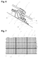
- a covered with inventive components roof is in FIG. 7 shown.
- the upper profile is brought by a pivoting movement of the component to be mounted under the fixed lower profile.
- the upper 4 and lower 3 profile of the frame 11 are designed such that the upper profile 4 by a pivoting movement along a pivot axis parallel to an upper edge of the device with the lower profile 3 'of above the component 1 mounted on the substructure 6 identical Component 1 'can be brought into engagement.
- FIG. 5 The sequence of the assembly process of such a preferred embodiment of an inventive component is in FIG. 5 shown in three steps.
- a first step FIG. 5 (a)
- the component 1 to be mounted is placed on the support element 5 in a tilted position toward the ridge.
- the inner sealing lip 42 of the upper profile can thus under the outer Sealing lip 31 'are pushed.
- a second step FIG. 5 (b)
- a pivoting movement 9 along an axis parallel to the upper edge of the component the upper profile 4 with the lower profile 3 'engaged.
- the result is the labyrinth seal.
- FIG. 5 (c) In a third, final step, FIG. 5 (c) , The support elements 5 'of the component to be mounted 1 are fixed to the substructure 6, in the case shown on the right in FIG. 5 (c) by means of two screws 52.
- the support elements have already been inserted in advance for this purpose in the retaining groove 34 of the lower profile 3, so that the fitter has his hands free.
- the position of the support element 5 ' is chosen so that in the newly formed labyrinth seal the distances of the sealing lips are suitable to each other. Since these distances change with the length expansion of the component with temperature changes, the correct distance is advantageously determined on the basis of the currently prevailing ambient temperature, for example by means of a table.
- a suitable method is, for example, to measure before mounting the device of the support elements of the upstream device down.
- FIG. 6 shows an embodiment of the inventive device, analogous to FIG. 2 in which some additional advantageous elements are present.
- two undercut grooves of the upper 4 and lower 3 'profile block-shaped inserts 35, 45 are arranged. These may consist of a short metal block which is inserted into the longitudinal ends of said grooves and then clamped in the groove with a pressure screw 38 arranged in a through bore. Towards the longitudinal end of the profile, a further bore is arranged in the metal block 35, 45. This can be used as a replacement or in addition to the screw hole 33, 44 for connecting the profiles to the frame. Also shown is an optional spacer 51 (dashed line) which is plugged onto a corresponding lip of the support element 5.
- This spacer which is preferably made of plastic, serves to align the component to be mounted or the next support element 5 'still to be fastened during assembly easy way to set. It can be provided for different cases, for example, for different ambient temperatures during assembly differently sized spacers.
- the spacers are preferably designed so that they break easily when, for example, the component contracts with a change in temperature.
- FIG. 8 A further embodiment of a device 1 according to the invention is shown in FIG FIG. 8 shown in a longitudinal section analogous to FIG. 2 ,
- This variant differs from the embodiments of components FIG. 2 and 6 essentially by a different attachment of the panel 12, 12 'in the frame 11.
- the profiles 2, 2', 3, 4 of the frame 11 on a mounting surface 17 on which the panel is mounted.
- a spacer element 15 is fixed on the mounting surface 17, for example in the form of a plastic strip, for example by gluing.
- the panel 12 is attached, for example, also by gluing.
- the joint can be filled with a sealant such as a silicone sealant. The result is a watertight, substantially planar outer surface of the inventive element 11, on the water can flow easily. Ingress of water to the inside 14 is prevented by the seal 16.
- profiles of a certain depth h1 can easily be combined with panels of different thickness h2 to form components 1 according to the invention by selecting the thickness h3 of the spacers 15 such that the surface of the panel 2 is flush with the outer edge 30 of the lower profile 3. Since the panel 12 need not be threaded into a U-shaped groove of the frame 11, the frame 11 can be completely pre-assembled before the panel 12 has to be mounted. Components according to the invention can be manufactured so quickly and inexpensively, and an automated Production is easily possible. The attachment of the sealant is also better controllable than a U-profile.
Landscapes
- Engineering & Computer Science (AREA)
- Architecture (AREA)
- Civil Engineering (AREA)
- Structural Engineering (AREA)
- Physics & Mathematics (AREA)
- Life Sciences & Earth Sciences (AREA)
- Sustainable Development (AREA)
- Sustainable Energy (AREA)
- Thermal Sciences (AREA)
- Chemical & Material Sciences (AREA)
- Combustion & Propulsion (AREA)
- Mechanical Engineering (AREA)
- General Engineering & Computer Science (AREA)
- Roof Covering Using Slabs Or Stiff Sheets (AREA)
Applications Claiming Priority (1)
| Application Number | Priority Date | Filing Date | Title |
|---|---|---|---|
| CH01938/08A CH700095B1 (de) | 2008-12-09 | 2008-12-09 | Bauelement zur Verkleidung von Gebäuden. |
Publications (2)
| Publication Number | Publication Date |
|---|---|
| EP2196594A1 true EP2196594A1 (fr) | 2010-06-16 |
| EP2196594B1 EP2196594B1 (fr) | 2019-04-24 |
Family
ID=42041679
Family Applications (1)
| Application Number | Title | Priority Date | Filing Date |
|---|---|---|---|
| EP09178519.6A Active EP2196594B1 (fr) | 2008-12-09 | 2009-12-09 | Elément de revêtement de bâtiments |
Country Status (2)
| Country | Link |
|---|---|
| EP (1) | EP2196594B1 (fr) |
| CH (1) | CH700095B1 (fr) |
Cited By (20)
| Publication number | Priority date | Publication date | Assignee | Title |
|---|---|---|---|---|
| FR2963801A1 (fr) * | 2010-08-16 | 2012-02-17 | Solframe | Dispositif modulaire qui permet d'assurer la couverture d'une surface telle que la toiture d'un batiment ainsi que la production d'electricite |
| FR2967433A1 (fr) * | 2010-11-15 | 2012-05-18 | Harmony Air Conditioning | Dispositif de fixation de panneaux photovoltaiques integres. |
| FR2967704A1 (fr) * | 2010-11-22 | 2012-05-25 | Abcd Internat | Dispositif d'integration de panneaux, en particulier de panneaux solaires sur une toiture de batiment, et couverture de batiment en faisant application |
| ITAN20110002A1 (it) * | 2011-01-17 | 2012-07-18 | Energy Resources S P A | Sistema per il supporto e il fissaggio con sormonto impermeabile per pannelli piani o moduli fotovoltaici |
| FR2970989A1 (fr) * | 2011-02-01 | 2012-08-03 | Lm Ind | Dispositif support de panneaux photovoltaiques en toiture, antivol |
| EP2527763A2 (fr) | 2011-05-27 | 2012-11-28 | Markus Gisler | Système d'habillage destiné à l'habillage d'une surface extérieure d'un bâtiment |
| ITRM20110362A1 (it) * | 2011-07-12 | 2013-01-13 | Mauro Pula | Sistema integrato di pannelli, preferibilmente fotovoltaici. |
| FR2979365A1 (fr) * | 2011-08-31 | 2013-03-01 | Integrasol | Dispositif d'integration et de fixation d'un panneau photovoltaique a une toiture. |
| AT512032B1 (de) * | 2011-12-12 | 2013-05-15 | Lenz Bernhard | Anordnung zur befestigung von platten |
| DE102011122340A1 (de) * | 2011-12-23 | 2013-06-27 | Centrotherm Photovoltaics Ag | Photovoltaikanlage und ein Verfahren zur Herstellung einer Photovoltaikanlage |
| EP2617914A1 (fr) * | 2012-01-19 | 2013-07-24 | Josef Rupp | Plaque de toit et système de recouvrement de toit |
| EP2662644A1 (fr) * | 2012-05-09 | 2013-11-13 | C-Lean S.r.l. | Ensemble d'installation de panneaux photovoltaïques |
| EP2672198A1 (fr) * | 2012-06-06 | 2013-12-11 | Folta, Maren | Support de module solaire pour le montage de modules photovoltaïques comme modules intégrés |
| EP2679929A1 (fr) | 2012-06-26 | 2014-01-01 | Centrosolar AG | Système de montage et d'étanchéité pour l'intégration d'une multitude de modules en forme de plaques dans un toit incliné |
| WO2017162433A1 (fr) * | 2016-03-25 | 2017-09-28 | Ewen Estill | Montage de panneau solaire |
| JP2019190269A (ja) * | 2018-04-20 | 2019-10-31 | 王 家壽WANG, Jia Shou | ソーラーパネル設置架台 |
| CN114704032A (zh) * | 2022-01-06 | 2022-07-05 | 江苏通灵电器股份有限公司 | 新型屋顶一体化光伏分布结构及屋顶一体化光伏电站 |
| US11444569B2 (en) * | 2020-10-14 | 2022-09-13 | GAF Energy LLC | Mounting apparatus for photovoltaic modules |
| WO2022268398A1 (fr) * | 2021-06-25 | 2022-12-29 | Paxos Consulting & Engineering GmbH & Co. KG | Tuile solaire et procédé de fabrication d'une tuile solaire |
| WO2022268399A1 (fr) * | 2021-06-25 | 2022-12-29 | Paxos Consulting & Engineering GmbH & Co. KG | Tuile de toit solaire, toit comportant une tuile de toit solaire, procédé de pose et de retrait d'une tuile de toit solaire |
Families Citing this family (58)
| Publication number | Priority date | Publication date | Assignee | Title |
|---|---|---|---|---|
| US11012024B2 (en) * | 2018-07-03 | 2021-05-18 | Building Materials Investment Corporation | Roof integrated photovoltaic system with improved serviceability |
| US11398795B2 (en) | 2019-12-20 | 2022-07-26 | GAF Energy LLC | Roof integrated photovoltaic system |
| CA3165505A1 (fr) | 2020-01-22 | 2021-07-29 | Nathan Peterson | Bardeaux de toiture photovoltaiques integres, procedes, systemes et kits associes |
| EP4107790A4 (fr) | 2020-02-18 | 2024-03-13 | Gaf Energy LLC | Module photovoltaïque à superstrat texturé conférant un aspect imitant un bardeau |
| US11961928B2 (en) | 2020-02-27 | 2024-04-16 | GAF Energy LLC | Photovoltaic module with light-scattering encapsulant providing shingle-mimicking appearance |
| EP4111507A4 (fr) | 2020-02-27 | 2024-03-27 | Gaf Energy LLC | Module photovoltaïque avec agent d'encapsulation diffusant la lumière fournissant un aspect imitant le bardeau |
| WO2021207238A1 (fr) | 2020-04-09 | 2021-10-14 | GAF Energy LLC | Module photovoltaïque stratifié tridimensionnel |
| US11217715B2 (en) | 2020-04-30 | 2022-01-04 | GAF Energy LLC | Photovoltaic module frontsheet and backsheet |
| CA3176241A1 (fr) | 2020-05-13 | 2021-11-18 | GAF Energy LLC | Passe-cable electrique |
| CN115769383A (zh) | 2020-06-04 | 2023-03-07 | Gaf能源有限责任公司 | 光伏屋顶板及其安装方法 |
| WO2022020490A1 (fr) | 2020-07-22 | 2022-01-27 | GAF Energy LLC | Modules photovoltaïques |
| WO2022035473A1 (fr) | 2020-08-11 | 2022-02-17 | GAF Energy LLC | Système photovoltaïque monté sur le toit et procédé de transfert sans fil d'énergie électrique |
| CN116420231A (zh) | 2020-09-03 | 2023-07-11 | Gaf能源有限责任公司 | 建筑集成光伏系统 |
| US11545928B2 (en) | 2020-10-13 | 2023-01-03 | GAF Energy LLC | Solar roofing system |
| US11454027B2 (en) | 2020-10-29 | 2022-09-27 | GAF Energy LLC | System of roofing and photovoltaic shingles and methods of installing same |
| US11486144B2 (en) | 2020-11-12 | 2022-11-01 | GAF Energy LLC | Roofing shingles with handles |
| WO2022103841A1 (fr) | 2020-11-13 | 2022-05-19 | GAF Energy LLC | Systèmes et procédés pour modules photovoltaïques |
| MX2023006559A (es) | 2020-12-02 | 2023-09-18 | GAF Energy LLC | Aletas escalonadas para tejas fotovoltáicas para techos. |
| CA3205363A1 (fr) | 2021-01-19 | 2022-07-28 | Thierry Nguyen | Caracteristiques de deversement d'eau pour bardeaux de toiture |
| MX2023009726A (es) | 2021-02-19 | 2023-11-09 | GAF Energy LLC | Módulo fotovoltaico para un techo con cinta de fibra continua. |
| US12568694B2 (en) | 2021-03-19 | 2026-03-03 | GAF Energy LLC | Photovoltaic module with a laminated potted printed circuit board |
| MX2023011156A (es) | 2021-03-29 | 2023-10-05 | GAF Energy LLC | Componentes electricos para sitemas fotovoltaicos. |
| MX2023013029A (es) | 2021-05-06 | 2023-11-16 | GAF Energy LLC | Modulo fotovoltaico con bordes perimetrales transparentes. |
| MX2023014362A (es) | 2021-06-02 | 2023-12-15 | GAF Energy LLC | Modulo fotovoltaico con encapsulante de dispersion de la luz que proporciona una apariencia que imita a las tejas. |
| WO2022259054A1 (fr) * | 2021-06-12 | 2022-12-15 | Arka Energy Inc. | Ensemble pour monter des tuiles sur une surface |
| US12009781B2 (en) | 2021-07-06 | 2024-06-11 | GAF Energy LLC | Jumper module for photovoltaic systems |
| US11512480B1 (en) | 2021-07-16 | 2022-11-29 | GAF Energy LLC | Roof material storage bracket |
| US11728759B2 (en) | 2021-09-01 | 2023-08-15 | GAF Energy LLC | Photovoltaic modules for commercial roofing |
| WO2023141566A1 (fr) | 2022-01-20 | 2023-07-27 | GAF Energy LLC | Bardeaux de toiture pour imiter l'aspect de modules photovoltaïques |
| US12013153B2 (en) | 2022-02-08 | 2024-06-18 | GAF Energy LLC | Building integrated photovoltaic system |
| US12209414B2 (en) | 2022-02-23 | 2025-01-28 | GAF Energy LLC | Roofing shingle and method of manufacturing same |
| WO2023173019A1 (fr) | 2022-03-10 | 2023-09-14 | GAF Energy LLC | Encapsulant et feuille arrière combinés pour modules photovoltaïques |
| US12199550B2 (en) | 2022-04-08 | 2025-01-14 | GAF Energy LLC | Low profile connector for solar roofing systems |
| CA3257758A1 (fr) | 2022-06-06 | 2023-12-14 | GAF Energy LLC | Indicateurs de composants actifs pour systèmes photovoltaïques |
| US12325996B2 (en) | 2022-07-15 | 2025-06-10 | GAF Energy LLC | Solar roofing system with fiber composite roofing shingles |
| US12145348B2 (en) | 2022-08-24 | 2024-11-19 | GAF Energy LLC | System for forming a roofing membrane, and associated method |
| EP4581684A1 (fr) | 2022-08-29 | 2025-07-09 | Gaf Energy LLC | Modules photovoltaïques à couches décalées |
| US12034089B2 (en) | 2022-09-01 | 2024-07-09 | GAF Energy LLC | Anti-reflective photovoltaic shingles and related methods |
| WO2024059462A1 (fr) | 2022-09-13 | 2024-03-21 | GAF Energy LLC | Système de toiture à capteurs et procédé associé |
| US12015374B2 (en) | 2022-09-26 | 2024-06-18 | GAF Energy LLC | Photovoltaic modules integrated with building siding and fencing |
| WO2024073498A1 (fr) | 2022-09-29 | 2024-04-04 | GAF Energy LLC | Module de raccordement avec manchon |
| US12031332B2 (en) | 2022-10-25 | 2024-07-09 | GAF Energy LLC | Roofing materials and related methods |
| US12231075B2 (en) | 2022-10-27 | 2025-02-18 | GAF Energy LLC | Building integrated photovoltaic systems |
| US12413183B2 (en) | 2022-11-15 | 2025-09-09 | GAF Energy LLC | Electrical cable passthrough for photovoltaic systems |
| US11811361B1 (en) | 2022-12-14 | 2023-11-07 | GAF Energy LLC | Rapid shutdown device for photovoltaic modules |
| US12445089B2 (en) | 2023-02-03 | 2025-10-14 | GAF Energy LLC | Photovoltaic module, and associated kit, system, and method |
| US12355390B1 (en) | 2023-02-03 | 2025-07-08 | GAF Energy LLC | Solar shingle and associated roofing system and method |
| US12413174B2 (en) | 2023-02-21 | 2025-09-09 | GAF Energy LLC | Roofing system including photovoltaic module wireway cover, and associated method |
| CA3229888A1 (en) | 2023-02-23 | 2025-04-25 | GAF Energy LLC | Photovoltaic shingles with multi-module power electronics |
| US12506440B2 (en) | 2023-02-28 | 2025-12-23 | GAF Energy LLC | Photovoltaic modules with energy storage components |
| CA3231973A1 (en) | 2023-03-14 | 2025-06-26 | GAF Energy LLC | Integrated cell and circuit interconnection |
| US12009782B1 (en) | 2023-04-04 | 2024-06-11 | GAF Energy LLC | Photovoltaic systems with wireways |
| US12413177B2 (en) | 2023-08-31 | 2025-09-09 | GAF Energy LLC | Photovoltaic modules and roofing shingles with nail zones |
| US12451838B1 (en) | 2023-10-06 | 2025-10-21 | GAF Energy LLC | Failsafe functionality for photovoltaic modules |
| WO2025090902A1 (fr) | 2023-10-26 | 2025-05-01 | GAF Energy LLC | Systèmes de toiture à protection contre l'entrée d'eau |
| WO2025122742A1 (fr) | 2023-12-05 | 2025-06-12 | GAF Energy LLC | Système de toiture pour la prévention de la déformation d'un bardeau de toiture |
| WO2025217150A1 (fr) | 2024-04-10 | 2025-10-16 | GAF Energy LLC | Bardeaux de toiture à structure ignifuge |
| US12540474B2 (en) | 2024-07-22 | 2026-02-03 | GAF Energy LLC | Electrically grounding metal roofing shingles with photovoltaic systems |
Citations (2)
| Publication number | Priority date | Publication date | Assignee | Title |
|---|---|---|---|---|
| FR2465315A1 (fr) * | 1979-09-10 | 1981-03-20 | Radiotechnique Compelec | Panneau generateur photovoltaique assurant l'etancheite aux intemperies d'une toiture par pose directe sur la charpente |
| DE9209228U1 (de) * | 1991-07-11 | 1992-11-05 | Alpha Real AG, Zürich | Dacheindeckung und Bauelement mit Solarzellen |
-
2008
- 2008-12-09 CH CH01938/08A patent/CH700095B1/de unknown
-
2009
- 2009-12-09 EP EP09178519.6A patent/EP2196594B1/fr active Active
Patent Citations (2)
| Publication number | Priority date | Publication date | Assignee | Title |
|---|---|---|---|---|
| FR2465315A1 (fr) * | 1979-09-10 | 1981-03-20 | Radiotechnique Compelec | Panneau generateur photovoltaique assurant l'etancheite aux intemperies d'une toiture par pose directe sur la charpente |
| DE9209228U1 (de) * | 1991-07-11 | 1992-11-05 | Alpha Real AG, Zürich | Dacheindeckung und Bauelement mit Solarzellen |
Cited By (28)
| Publication number | Priority date | Publication date | Assignee | Title |
|---|---|---|---|---|
| FR2963801A1 (fr) * | 2010-08-16 | 2012-02-17 | Solframe | Dispositif modulaire qui permet d'assurer la couverture d'une surface telle que la toiture d'un batiment ainsi que la production d'electricite |
| WO2012022902A1 (fr) * | 2010-08-16 | 2012-02-23 | Solframe | Dispositif modulaire qui permet d'assurer la couverture d'une surface telle que la toiture d'un batiment ainsi que la production d'electricité. |
| FR2967433A1 (fr) * | 2010-11-15 | 2012-05-18 | Harmony Air Conditioning | Dispositif de fixation de panneaux photovoltaiques integres. |
| FR2967704A1 (fr) * | 2010-11-22 | 2012-05-25 | Abcd Internat | Dispositif d'integration de panneaux, en particulier de panneaux solaires sur une toiture de batiment, et couverture de batiment en faisant application |
| ITAN20110002A1 (it) * | 2011-01-17 | 2012-07-18 | Energy Resources S P A | Sistema per il supporto e il fissaggio con sormonto impermeabile per pannelli piani o moduli fotovoltaici |
| FR2970989A1 (fr) * | 2011-02-01 | 2012-08-03 | Lm Ind | Dispositif support de panneaux photovoltaiques en toiture, antivol |
| EP2527763A2 (fr) | 2011-05-27 | 2012-11-28 | Markus Gisler | Système d'habillage destiné à l'habillage d'une surface extérieure d'un bâtiment |
| ITRM20110362A1 (it) * | 2011-07-12 | 2013-01-13 | Mauro Pula | Sistema integrato di pannelli, preferibilmente fotovoltaici. |
| EP2546585A1 (fr) * | 2011-07-12 | 2013-01-16 | Mauro Pula | Système de panneaux intégré |
| FR2979365A1 (fr) * | 2011-08-31 | 2013-03-01 | Integrasol | Dispositif d'integration et de fixation d'un panneau photovoltaique a une toiture. |
| AT512032B1 (de) * | 2011-12-12 | 2013-05-15 | Lenz Bernhard | Anordnung zur befestigung von platten |
| AT512032A4 (de) * | 2011-12-12 | 2013-05-15 | Lenz Bernhard | Anordnung zur befestigung von platten |
| EP2604770A3 (fr) * | 2011-12-12 | 2017-12-06 | Bernhard Lenz | Agencement de fixation de plaques |
| DE102011122340A1 (de) * | 2011-12-23 | 2013-06-27 | Centrotherm Photovoltaics Ag | Photovoltaikanlage und ein Verfahren zur Herstellung einer Photovoltaikanlage |
| EP2617914A1 (fr) * | 2012-01-19 | 2013-07-24 | Josef Rupp | Plaque de toit et système de recouvrement de toit |
| EP2662644A1 (fr) * | 2012-05-09 | 2013-11-13 | C-Lean S.r.l. | Ensemble d'installation de panneaux photovoltaïques |
| EP2672198A1 (fr) * | 2012-06-06 | 2013-12-11 | Folta, Maren | Support de module solaire pour le montage de modules photovoltaïques comme modules intégrés |
| EP2679929A1 (fr) | 2012-06-26 | 2014-01-01 | Centrosolar AG | Système de montage et d'étanchéité pour l'intégration d'une multitude de modules en forme de plaques dans un toit incliné |
| WO2017162433A1 (fr) * | 2016-03-25 | 2017-09-28 | Ewen Estill | Montage de panneau solaire |
| GB2548983A (en) * | 2016-03-25 | 2017-10-04 | Estill Ewen | Solar panel mounting |
| GB2561326A (en) * | 2016-03-25 | 2018-10-10 | Estill Ewen | Solar panel mounting |
| JP2019190269A (ja) * | 2018-04-20 | 2019-10-31 | 王 家壽WANG, Jia Shou | ソーラーパネル設置架台 |
| US11444569B2 (en) * | 2020-10-14 | 2022-09-13 | GAF Energy LLC | Mounting apparatus for photovoltaic modules |
| US11689149B2 (en) | 2020-10-14 | 2023-06-27 | GAF Energy LLC | Mounting apparatus for photovoltaic modules |
| WO2022268398A1 (fr) * | 2021-06-25 | 2022-12-29 | Paxos Consulting & Engineering GmbH & Co. KG | Tuile solaire et procédé de fabrication d'une tuile solaire |
| WO2022268399A1 (fr) * | 2021-06-25 | 2022-12-29 | Paxos Consulting & Engineering GmbH & Co. KG | Tuile de toit solaire, toit comportant une tuile de toit solaire, procédé de pose et de retrait d'une tuile de toit solaire |
| CN114704032A (zh) * | 2022-01-06 | 2022-07-05 | 江苏通灵电器股份有限公司 | 新型屋顶一体化光伏分布结构及屋顶一体化光伏电站 |
| CN114704032B (zh) * | 2022-01-06 | 2024-06-07 | 江苏通灵电器股份有限公司 | 新型屋顶一体化光伏分布结构及屋顶一体化光伏电站 |
Also Published As
| Publication number | Publication date |
|---|---|
| CH700095A2 (de) | 2010-06-15 |
| CH700095B1 (de) | 2012-09-14 |
| EP2196594B1 (fr) | 2019-04-24 |
Similar Documents
| Publication | Publication Date | Title |
|---|---|---|
| EP2196594B1 (fr) | Elément de revêtement de bâtiments | |
| EP2784241B1 (fr) | Couverture de toit pour l'utilisation de l'énergie solaire | |
| EP1703037B1 (fr) | Revêtement pour toit ou paroi | |
| EP2238392B1 (fr) | Système de fixation pour un composant en forme de panneau | |
| EP1734588B1 (fr) | Recouvrement de toiture | |
| DE9209228U1 (de) | Dacheindeckung und Bauelement mit Solarzellen | |
| EP2381188A2 (fr) | Système de montage de module solaire et enveloppe extérieure de bâtiment | |
| EP1362967A1 (fr) | Dispositif comprenant des éléments de construction plats, en forme de plaques | |
| DE202011109727U1 (de) | Anordnung zur Befestigung von Plattenelementen | |
| EP2679929A1 (fr) | Système de montage et d'étanchéité pour l'intégration d'une multitude de modules en forme de plaques dans un toit incliné | |
| EP2527763B1 (fr) | Système d'habillage destiné à l'habillage d'une surface extérieure d'un bâtiment | |
| AT523015B1 (de) | Rahmen eines Moduls für ein modulares Photovoltaiksystem, damit hergestelltes Modul und modulares Photovoltaiksystem | |
| AT403181B (de) | Verfahren zum freihalten von regenwasser-abflüssen eines daches von eisbildung sowie vorrichtung zur durchführung dieses verfahrens | |
| EP2541618A1 (fr) | Installation de système solaire sur toiture | |
| DE202007014258U1 (de) | Befestigungsvorrichtung für Solarmodule | |
| EP0960990B1 (fr) | Dispositif de recouvrement d'une toiture inclinée | |
| DE202010008139U1 (de) | Dacheindeckung | |
| DE10309445B3 (de) | Rahmensystem für Dachbauelemente | |
| EP2617914A1 (fr) | Plaque de toit et système de recouvrement de toit | |
| EP2476971B1 (fr) | Collecteur Solaire | |
| DE102011051283A1 (de) | Dachelement mit einem Solarmodul sowie ein aus mehreren der Dachelemente zusammengesetztes Dach | |
| EP2896909B1 (fr) | Système de montage en toiture de modules solaires | |
| DE4434879C1 (de) | Belüftetes Aluminium-Dach aus Aluminium-Lamellenprofilen auf Aluminium-Lisenenträgern mit Gummidichtung | |
| DE19606442C1 (de) | Dacheindeckung aus Aluminium oder Kunststoff | |
| DE102008022153A1 (de) | Vorrichtung zur Befestigung von Photovoltaikmodulen |
Legal Events
| Date | Code | Title | Description |
|---|---|---|---|
| PUAI | Public reference made under article 153(3) epc to a published international application that has entered the european phase |
Free format text: ORIGINAL CODE: 0009012 |
|
| AK | Designated contracting states |
Kind code of ref document: A1 Designated state(s): AT BE BG CH CY CZ DE DK EE ES FI FR GB GR HR HU IE IS IT LI LT LU LV MC MK MT NL NO PL PT RO SE SI SK SM TR |
|
| AX | Request for extension of the european patent |
Extension state: AL BA RS |
|
| 17P | Request for examination filed |
Effective date: 20101028 |
|
| 17Q | First examination report despatched |
Effective date: 20101126 |
|
| RIC1 | Information provided on ipc code assigned before grant |
Ipc: E04D 3/02 20060101ALI20111019BHEP Ipc: F24J 2/04 20060101AFI20111019BHEP Ipc: H01L 31/042 20060101ALI20111019BHEP Ipc: F24J 2/52 20060101ALI20111019BHEP Ipc: H01L 31/048 20060101ALI20111019BHEP |
|
| REG | Reference to a national code |
Ref country code: DE Ref legal event code: R079 Ref document number: 502009015728 Country of ref document: DE Free format text: PREVIOUS MAIN CLASS: E04D0003020000 Ipc: H01L0031042000 |
|
| GRAP | Despatch of communication of intention to grant a patent |
Free format text: ORIGINAL CODE: EPIDOSNIGR1 |
|
| STAA | Information on the status of an ep patent application or granted ep patent |
Free format text: STATUS: GRANT OF PATENT IS INTENDED |
|
| RIC1 | Information provided on ipc code assigned before grant |
Ipc: E04D 3/02 20060101ALI20180928BHEP Ipc: F24S 20/00 20180101ALI20180928BHEP Ipc: H01L 31/042 20060101AFI20180928BHEP Ipc: H01L 31/048 20060101ALI20180928BHEP |
|
| INTG | Intention to grant announced |
Effective date: 20181018 |
|
| RIC1 | Information provided on ipc code assigned before grant |
Ipc: H01L 31/042 20140101AFI20180928BHEP Ipc: F24S 20/00 20180101ALI20180928BHEP Ipc: E04D 3/02 20060101ALI20180928BHEP Ipc: H01L 31/048 20140101ALI20180928BHEP |
|
| GRAS | Grant fee paid |
Free format text: ORIGINAL CODE: EPIDOSNIGR3 |
|
| GRAJ | Information related to disapproval of communication of intention to grant by the applicant or resumption of examination proceedings by the epo deleted |
Free format text: ORIGINAL CODE: EPIDOSDIGR1 |
|
| GRAL | Information related to payment of fee for publishing/printing deleted |
Free format text: ORIGINAL CODE: EPIDOSDIGR3 |
|
| STAA | Information on the status of an ep patent application or granted ep patent |
Free format text: STATUS: EXAMINATION IS IN PROGRESS |
|
| GRAR | Information related to intention to grant a patent recorded |
Free format text: ORIGINAL CODE: EPIDOSNIGR71 |
|
| STAA | Information on the status of an ep patent application or granted ep patent |
Free format text: STATUS: GRANT OF PATENT IS INTENDED |
|
| GRAA | (expected) grant |
Free format text: ORIGINAL CODE: 0009210 |
|
| STAA | Information on the status of an ep patent application or granted ep patent |
Free format text: STATUS: THE PATENT HAS BEEN GRANTED |
|
| INTC | Intention to grant announced (deleted) | ||
| AK | Designated contracting states |
Kind code of ref document: B1 Designated state(s): AT BE BG CH CY CZ DE DK EE ES FI FR GB GR HR HU IE IS IT LI LT LU LV MC MK MT NL NO PL PT RO SE SI SK SM TR |
|
| INTG | Intention to grant announced |
Effective date: 20190319 |
|
| REG | Reference to a national code |
Ref country code: GB Ref legal event code: FG4D Free format text: NOT ENGLISH |
|
| REG | Reference to a national code |
Ref country code: CH Ref legal event code: EP |
|
| REG | Reference to a national code |
Ref country code: AT Ref legal event code: REF Ref document number: 1125166 Country of ref document: AT Kind code of ref document: T Effective date: 20190515 Ref country code: IE Ref legal event code: FG4D Free format text: LANGUAGE OF EP DOCUMENT: GERMAN |
|
| REG | Reference to a national code |
Ref country code: DE Ref legal event code: R096 Ref document number: 502009015728 Country of ref document: DE |
|
| REG | Reference to a national code |
Ref country code: CH Ref legal event code: NV Representative=s name: RENTSCH PARTNER AG, CH |
|
| REG | Reference to a national code |
Ref country code: NL Ref legal event code: MP Effective date: 20190424 |
|
| REG | Reference to a national code |
Ref country code: LT Ref legal event code: MG4D |
|
| PG25 | Lapsed in a contracting state [announced via postgrant information from national office to epo] |
Ref country code: NL Free format text: LAPSE BECAUSE OF FAILURE TO SUBMIT A TRANSLATION OF THE DESCRIPTION OR TO PAY THE FEE WITHIN THE PRESCRIBED TIME-LIMIT Effective date: 20190424 |
|
| PG25 | Lapsed in a contracting state [announced via postgrant information from national office to epo] |
Ref country code: ES Free format text: LAPSE BECAUSE OF FAILURE TO SUBMIT A TRANSLATION OF THE DESCRIPTION OR TO PAY THE FEE WITHIN THE PRESCRIBED TIME-LIMIT Effective date: 20190424 Ref country code: SE Free format text: LAPSE BECAUSE OF FAILURE TO SUBMIT A TRANSLATION OF THE DESCRIPTION OR TO PAY THE FEE WITHIN THE PRESCRIBED TIME-LIMIT Effective date: 20190424 Ref country code: PT Free format text: LAPSE BECAUSE OF FAILURE TO SUBMIT A TRANSLATION OF THE DESCRIPTION OR TO PAY THE FEE WITHIN THE PRESCRIBED TIME-LIMIT Effective date: 20190824 Ref country code: HR Free format text: LAPSE BECAUSE OF FAILURE TO SUBMIT A TRANSLATION OF THE DESCRIPTION OR TO PAY THE FEE WITHIN THE PRESCRIBED TIME-LIMIT Effective date: 20190424 Ref country code: LT Free format text: LAPSE BECAUSE OF FAILURE TO SUBMIT A TRANSLATION OF THE DESCRIPTION OR TO PAY THE FEE WITHIN THE PRESCRIBED TIME-LIMIT Effective date: 20190424 Ref country code: FI Free format text: LAPSE BECAUSE OF FAILURE TO SUBMIT A TRANSLATION OF THE DESCRIPTION OR TO PAY THE FEE WITHIN THE PRESCRIBED TIME-LIMIT Effective date: 20190424 Ref country code: NO Free format text: LAPSE BECAUSE OF FAILURE TO SUBMIT A TRANSLATION OF THE DESCRIPTION OR TO PAY THE FEE WITHIN THE PRESCRIBED TIME-LIMIT Effective date: 20190724 |
|
| PG25 | Lapsed in a contracting state [announced via postgrant information from national office to epo] |
Ref country code: PL Free format text: LAPSE BECAUSE OF FAILURE TO SUBMIT A TRANSLATION OF THE DESCRIPTION OR TO PAY THE FEE WITHIN THE PRESCRIBED TIME-LIMIT Effective date: 20190424 Ref country code: BG Free format text: LAPSE BECAUSE OF FAILURE TO SUBMIT A TRANSLATION OF THE DESCRIPTION OR TO PAY THE FEE WITHIN THE PRESCRIBED TIME-LIMIT Effective date: 20190724 Ref country code: GR Free format text: LAPSE BECAUSE OF FAILURE TO SUBMIT A TRANSLATION OF THE DESCRIPTION OR TO PAY THE FEE WITHIN THE PRESCRIBED TIME-LIMIT Effective date: 20190725 Ref country code: LV Free format text: LAPSE BECAUSE OF FAILURE TO SUBMIT A TRANSLATION OF THE DESCRIPTION OR TO PAY THE FEE WITHIN THE PRESCRIBED TIME-LIMIT Effective date: 20190424 |
|
| PG25 | Lapsed in a contracting state [announced via postgrant information from national office to epo] |
Ref country code: IS Free format text: LAPSE BECAUSE OF FAILURE TO SUBMIT A TRANSLATION OF THE DESCRIPTION OR TO PAY THE FEE WITHIN THE PRESCRIBED TIME-LIMIT Effective date: 20190824 |
|
| REG | Reference to a national code |
Ref country code: DE Ref legal event code: R097 Ref document number: 502009015728 Country of ref document: DE |
|
| PG25 | Lapsed in a contracting state [announced via postgrant information from national office to epo] |
Ref country code: DK Free format text: LAPSE BECAUSE OF FAILURE TO SUBMIT A TRANSLATION OF THE DESCRIPTION OR TO PAY THE FEE WITHIN THE PRESCRIBED TIME-LIMIT Effective date: 20190424 Ref country code: SK Free format text: LAPSE BECAUSE OF FAILURE TO SUBMIT A TRANSLATION OF THE DESCRIPTION OR TO PAY THE FEE WITHIN THE PRESCRIBED TIME-LIMIT Effective date: 20190424 Ref country code: RO Free format text: LAPSE BECAUSE OF FAILURE TO SUBMIT A TRANSLATION OF THE DESCRIPTION OR TO PAY THE FEE WITHIN THE PRESCRIBED TIME-LIMIT Effective date: 20190424 Ref country code: CZ Free format text: LAPSE BECAUSE OF FAILURE TO SUBMIT A TRANSLATION OF THE DESCRIPTION OR TO PAY THE FEE WITHIN THE PRESCRIBED TIME-LIMIT Effective date: 20190424 Ref country code: EE Free format text: LAPSE BECAUSE OF FAILURE TO SUBMIT A TRANSLATION OF THE DESCRIPTION OR TO PAY THE FEE WITHIN THE PRESCRIBED TIME-LIMIT Effective date: 20190424 |
|
| PG25 | Lapsed in a contracting state [announced via postgrant information from national office to epo] |
Ref country code: SM Free format text: LAPSE BECAUSE OF FAILURE TO SUBMIT A TRANSLATION OF THE DESCRIPTION OR TO PAY THE FEE WITHIN THE PRESCRIBED TIME-LIMIT Effective date: 20190424 Ref country code: IT Free format text: LAPSE BECAUSE OF FAILURE TO SUBMIT A TRANSLATION OF THE DESCRIPTION OR TO PAY THE FEE WITHIN THE PRESCRIBED TIME-LIMIT Effective date: 20190424 |
|
| PLBE | No opposition filed within time limit |
Free format text: ORIGINAL CODE: 0009261 |
|
| STAA | Information on the status of an ep patent application or granted ep patent |
Free format text: STATUS: NO OPPOSITION FILED WITHIN TIME LIMIT |
|
| PG25 | Lapsed in a contracting state [announced via postgrant information from national office to epo] |
Ref country code: TR Free format text: LAPSE BECAUSE OF FAILURE TO SUBMIT A TRANSLATION OF THE DESCRIPTION OR TO PAY THE FEE WITHIN THE PRESCRIBED TIME-LIMIT Effective date: 20190424 |
|
| 26N | No opposition filed |
Effective date: 20200127 |
|
| PG25 | Lapsed in a contracting state [announced via postgrant information from national office to epo] |
Ref country code: SI Free format text: LAPSE BECAUSE OF FAILURE TO SUBMIT A TRANSLATION OF THE DESCRIPTION OR TO PAY THE FEE WITHIN THE PRESCRIBED TIME-LIMIT Effective date: 20190424 |
|
| PG25 | Lapsed in a contracting state [announced via postgrant information from national office to epo] |
Ref country code: MC Free format text: LAPSE BECAUSE OF FAILURE TO SUBMIT A TRANSLATION OF THE DESCRIPTION OR TO PAY THE FEE WITHIN THE PRESCRIBED TIME-LIMIT Effective date: 20190424 |
|
| PG25 | Lapsed in a contracting state [announced via postgrant information from national office to epo] |
Ref country code: IE Free format text: LAPSE BECAUSE OF NON-PAYMENT OF DUE FEES Effective date: 20191209 Ref country code: LU Free format text: LAPSE BECAUSE OF NON-PAYMENT OF DUE FEES Effective date: 20191209 |
|
| PG25 | Lapsed in a contracting state [announced via postgrant information from national office to epo] |
Ref country code: CY Free format text: LAPSE BECAUSE OF FAILURE TO SUBMIT A TRANSLATION OF THE DESCRIPTION OR TO PAY THE FEE WITHIN THE PRESCRIBED TIME-LIMIT Effective date: 20190424 |
|
| PG25 | Lapsed in a contracting state [announced via postgrant information from national office to epo] |
Ref country code: HU Free format text: LAPSE BECAUSE OF FAILURE TO SUBMIT A TRANSLATION OF THE DESCRIPTION OR TO PAY THE FEE WITHIN THE PRESCRIBED TIME-LIMIT; INVALID AB INITIO Effective date: 20091209 Ref country code: MT Free format text: LAPSE BECAUSE OF FAILURE TO SUBMIT A TRANSLATION OF THE DESCRIPTION OR TO PAY THE FEE WITHIN THE PRESCRIBED TIME-LIMIT Effective date: 20190424 |
|
| PG25 | Lapsed in a contracting state [announced via postgrant information from national office to epo] |
Ref country code: MK Free format text: LAPSE BECAUSE OF FAILURE TO SUBMIT A TRANSLATION OF THE DESCRIPTION OR TO PAY THE FEE WITHIN THE PRESCRIBED TIME-LIMIT Effective date: 20190424 |
|
| REG | Reference to a national code |
Ref country code: DE Ref legal event code: R081 Ref document number: 502009015728 Country of ref document: DE Owner name: MEGASOL ENERGIE AG, CH Free format text: FORMER OWNER: GISLER, MARKUS, NIEDERBIPP, CH Ref country code: DE Ref legal event code: R082 Ref document number: 502009015728 Country of ref document: DE Representative=s name: MUELLER HOFFMANN & PARTNER PATENTANWAELTE MBB, DE |
|
| REG | Reference to a national code |
Ref country code: GB Ref legal event code: 732E Free format text: REGISTERED BETWEEN 20220915 AND 20220921 |
|
| REG | Reference to a national code |
Ref country code: AT Ref legal event code: PC Ref document number: 1125166 Country of ref document: AT Kind code of ref document: T Owner name: MEGASOL ENERGIE AG, CH Effective date: 20230228 |
|
| REG | Reference to a national code |
Ref country code: BE Ref legal event code: PD Owner name: MEGASOL ENERGIE AG; CH Free format text: DETAILS ASSIGNMENT: CHANGE OF OWNER(S), ASSIGNMENT; FORMER OWNER NAME: GISLER, MARKUS Effective date: 20230320 |
|
| REG | Reference to a national code |
Ref country code: DE Ref legal event code: R079 Ref document number: 502009015728 Country of ref document: DE Free format text: PREVIOUS MAIN CLASS: H01L0031042000 Ipc: H10F0019000000 |
|
| REG | Reference to a national code |
Ref country code: CH Ref legal event code: U11 Free format text: ST27 STATUS EVENT CODE: U-0-0-U10-U11 (AS PROVIDED BY THE NATIONAL OFFICE) Effective date: 20260101 |
|
| PGFP | Annual fee paid to national office [announced via postgrant information from national office to epo] |
Ref country code: DE Payment date: 20251211 Year of fee payment: 17 |
|
| PGFP | Annual fee paid to national office [announced via postgrant information from national office to epo] |
Ref country code: GB Payment date: 20251219 Year of fee payment: 17 |
|
| PGFP | Annual fee paid to national office [announced via postgrant information from national office to epo] |
Ref country code: AT Payment date: 20251222 Year of fee payment: 17 |
|
| PGFP | Annual fee paid to national office [announced via postgrant information from national office to epo] |
Ref country code: FR Payment date: 20251222 Year of fee payment: 17 |
|
| PGFP | Annual fee paid to national office [announced via postgrant information from national office to epo] |
Ref country code: BE Payment date: 20251219 Year of fee payment: 17 |
|
| PGFP | Annual fee paid to national office [announced via postgrant information from national office to epo] |
Ref country code: CH Payment date: 20260101 Year of fee payment: 17 |