EP2196624B1 - Aube de rotor de turbine à gaz - Google Patents
Aube de rotor de turbine à gaz Download PDFInfo
- Publication number
- EP2196624B1 EP2196624B1 EP09178286.2A EP09178286A EP2196624B1 EP 2196624 B1 EP2196624 B1 EP 2196624B1 EP 09178286 A EP09178286 A EP 09178286A EP 2196624 B1 EP2196624 B1 EP 2196624B1
- Authority
- EP
- European Patent Office
- Prior art keywords
- blade
- rotor
- rotor blade
- tension rod
- longitudinal direction
- Prior art date
- Legal status (The legal status is an assumption and is not a legal conclusion. Google has not performed a legal analysis and makes no representation as to the accuracy of the status listed.)
- Active
Links
Images
Classifications
-
- F—MECHANICAL ENGINEERING; LIGHTING; HEATING; WEAPONS; BLASTING
- F01—MACHINES OR ENGINES IN GENERAL; ENGINE PLANTS IN GENERAL; STEAM ENGINES
- F01D—NON-POSITIVE DISPLACEMENT MACHINES OR ENGINES, e.g. STEAM TURBINES
- F01D5/00—Blades; Blade-carrying members; Heating, heat-insulating, cooling or antivibration means on the blades or the members
- F01D5/12—Blades
- F01D5/14—Form or construction
- F01D5/147—Construction, i.e. structural features, e.g. of weight-saving hollow blades
-
- F—MECHANICAL ENGINEERING; LIGHTING; HEATING; WEAPONS; BLASTING
- F05—INDEXING SCHEMES RELATING TO ENGINES OR PUMPS IN VARIOUS SUBCLASSES OF CLASSES F01-F04
- F05D—INDEXING SCHEME FOR ASPECTS RELATING TO NON-POSITIVE-DISPLACEMENT MACHINES OR ENGINES, GAS-TURBINES OR JET-PROPULSION PLANTS
- F05D2240/00—Components
- F05D2240/20—Rotors
- F05D2240/30—Characteristics of rotor blades, i.e. of any element transforming dynamic fluid energy to or from rotational energy and being attached to a rotor
-
- F—MECHANICAL ENGINEERING; LIGHTING; HEATING; WEAPONS; BLASTING
- F05—INDEXING SCHEMES RELATING TO ENGINES OR PUMPS IN VARIOUS SUBCLASSES OF CLASSES F01-F04
- F05D—INDEXING SCHEME FOR ASPECTS RELATING TO NON-POSITIVE-DISPLACEMENT MACHINES OR ENGINES, GAS-TURBINES OR JET-PROPULSION PLANTS
- F05D2260/00—Function
- F05D2260/30—Retaining components in desired mutual position
- F05D2260/36—Retaining components in desired mutual position by a form fit connection, e.g. by interlocking
Definitions
- the present invention relates to the field of gas turbine technology. It relates to a blade for a gas turbine according to the preamble of claim 1.
- Uncooled hollow turbine blades are usually cast from a material. But it is also known ( US B1-6,331,217 ), large rotor blades of a gas turbine from several separately cast blade parts by liquid phase bonding together. Here, either the blade is divided in the blade longitudinal direction (Fig. 3 of the US B1-6,331,217 ) or the entire airfoil is separated from the platform and the blade root manufactured (Fig. 6 of the US B1-6,331,217 ). This leads, especially in the case of large blades, to the fact that, despite the subdivision, large castings for the airfoil have to be produced and positively connected to one another.
- a blade is known in which the profile sheet height according to several sections (1 a and 1 b) is composed.
- the blade core (2) which extends in one piece from the blade root to the blade tip, is not subdivided.
- the center of the document D1 is thus the subdivision of the blade from inside to outside into the central blade core and the blade core enveloping the blade core.
- EP 1 905 954 A is the pitch of the blade in the area of the blade root ( Fig. 1 . 2 ).
- the entire airfoil is in one piece, whereby the production is not significantly facilitated.
- the blade is composed of several individual parts, the material of each of which is adapted to the intended use of the item in question, and that each of the items is significantly smaller in dimensions than the composite blade, that the items of the blade a lower Blade part and an adjoining in the blade longitudinal direction of the upper blade member, wherein the blade is divided in blade longitudinal direction on the lower and upper blade portion, and that the lower blade portion includes the platform and at least a portion of the blade root.
- the invention thus pursues the idea to build a gas turbine blade from several, relatively small items of different materials whose material properties can be adapted to the respective local loads. Due to the possible variation of the materials, a clear optimization potential with respect to the own weight, the manufacturability and the manufacturing costs of the blade is revealed.
- the idea of the invention is therefore to build the gas turbine blade from several individual parts in order to be able to exploit targeted material properties and to avoid any size-related manufacturing problems.
- a clear separation of functions between the different parts is to be achieved. This is associated with the known and used materials with a relatively high density. This relationship can be represented by the so-called specific density. This is the relation between material strength values and their density. By such a split airfoil, the dimension of the individual castings can be significantly reduced.
- An embodiment of the blade according to the invention is characterized in that the individual parts are at least partially connected by positive locking.
- Another embodiment of the blade according to the invention is characterized in that the upper blade part includes the blade tip.
- a further embodiment is characterized in that, for receiving the centrifugal forces acting on the upper blade part, a tie rod extending in the longitudinal direction of the blade is arranged in the blade longitudinal direction, that the tie rod engages with its upper end with the lower end of the upper blade part, and that Tie rod with its lower end introduces the tensile forces in the blade root.
- the tie rod has a foot section on which forms part of the blade root and with which the tie rod engages behind the lower blade part.
- an inwardly angled first angle element is arranged on the upper blade part, wherein the tie rod engages with the upper blade part in that it engages behind the first angle element with a second angle element.
- the tie rod can also consist of several in the blade longitudinal direction arranged in parallel partial anchors, wherein the partial anchors are spaced transversely to the blade longitudinal direction from each other, and wherein the distance of the partial anchors is determined by subsequently usable spacers.
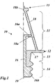
- Fig. 1 shows a longitudinal section through a (built) blade according to an embodiment of the invention.
- the blade 10 of the Fig. 1 consists of three separate components, namely an upper blade portion 18, a lower blade portion 17 and a tie rod 16.
- the blade 10 has an aerodynamically effective airfoil 11 extending in the blade longitudinal direction between a blade tip 15 and a platform 12.
- the airfoil 11 is divided longitudinally onto the upper blade part 18 and onto the lower blade part 17.
- a shroud segment 18b is formed at the upper end of the upper blade part 18.
- an inwardly projecting first angle member 18a is formed, behind which engages the inner tie rod 16 with a mounted at its upper end second angle member 16a and thus holds the upper blade member 18 against the centrifugal forces occurring.
- the upper blade part 18 is thus loaded only on train.
- the lower blade part 17 comprises the lower part of the blade 11, the platform 12 a shaft 13 and a part of a blade root 14, which in the shown example, a fir tree-like edge profile (with 3 teeth) has.
- Another part of the blade root 14 is formed by a foot section 16b, with which the tie rod 16 engages behind the lower blade part 17.
- the upper blade portion 18 and the lower blade portion 17 must have a significantly higher temperature and creep resistance than the inner tie rod 16.
- the materials used for the parts 17, 18 on the one hand and the part 16 on the other hand can be correspondingly different. Within the blade height, however, the temperatures vary so strongly that the use of differently adapted materials is also recommended for the two blade parts 17 and 18.
- Even the tie rod 16 can-as in Fig. 1 indicated by the different hatching - if necessary in the longitudinal direction consist of different materials. But it can also be made of a material throughout.
- the assembly of an inventive blade can be done in different ways: If the tie rod 16 is not divided in the longitudinal direction in a median plane 19, he can, for example, 90 ° twisted introduced from below into the blade interior and then by a rotation of 90 ° back into engagement with the angle member 18a at the lower end of the upper blade portion 18 are brought.
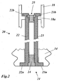
- a tie rod 21 divided in the longitudinal direction which comprises two partial anchors 22 and 23 which are mirror-symmetrical to one another and which are spaced apart transversely in the installed state and are kept at a distance by corresponding spacers 24 and 25.
- the two partial anchors 22, 23 are first inserted without spacers 24, 25 and without transverse spacing in the blade interior until the partial anchors 22, 23 can engage with their upper angle elements 22b, 23b behind the angle elements 18a of the airfoil.
- the upper (round) spacer 25 from below between the two partial anchors pushed up until he was in Fig. 2 has reached the position shown and the two partial anchors 22, 23 fixed in the hooked position.
- the lower spacer 24 is inserted between the partial anchors 22, 23 so that they are supported with lower angle elements from the inside on a shoulder on the blade root 14.
Landscapes
- Engineering & Computer Science (AREA)
- Architecture (AREA)
- Mechanical Engineering (AREA)
- General Engineering & Computer Science (AREA)
- Turbine Rotor Nozzle Sealing (AREA)
- Structures Of Non-Positive Displacement Pumps (AREA)
Claims (9)
- Aube (10, 20) pour une turbine à gaz, cette aube (10, 20) comprenant une pale (11), une pointe d'aube (15), un pied d'aube (14) et une plate-forme (12) formée entre la pointe d'aube (15) et le pied d'aube (14) et étant constituée de plusieurs parties individuelles (16, 17, 18), dont le matériau est adapté à l'utilisation de chacune des parties individuelles, caractérisée en ce que chacun des parties individuelles (16, 17, 18) présente des dimensions nettement inférieures à la pale assemblée (10, 20), en ce que les éléments individuels (16, 17, 18) de l'aube (10, 20) comprennent une partie d'aube inférieure (17) et une partie d'aube supérieure (18) la prolongeant dans la direction longitudinale de l'aube, la pale (11) étant divisée, dans la direction longitudinale de l'aube, dans les parties inférieure et supérieure de l'aube (17 ou 18) et en ce que la partie d'aube inférieure (17) comprend la plate-forme (12) et au moins une partie du pied d'aube.
- Aube selon la revendication 1, caractérisée en ce que les parties individuelles (16, 17, 18) sont reliées entre elles au moins partiellement par complémentarité de forme.
- Aube selon la revendication 1 ou 2, caractérisée en ce que la partie d'aube supérieure (18) comprend la pointe d'aube (15).
- Aube selon la revendication 1, caractérisée en ce que, pour l'absorption des forces centrifuges qui s'exercent sur la partie d'aube supérieure (18), à l'intérieur de l'aube (10, 20) se trouve un tirant d'ancrage (16, 21) s'étendant dans la direction longitudinale de l'aube, en ce que le tirant d'ancrage (16, 21) s'emboîte, avec son extrémité supérieure, avec l'extrémité inférieure de la partie d'aube supérieure (18) et en ce que le tirant d'ancrage (16, 21) transmet les forces de traction dans le pied de l'aube (14) avec son extrémité inférieure.
- Aube selon la revendication 4, caractérisé en ce que le tirant d'ancrage (16) comprend une portion de pied (16b) qui constitue une partie du pied d'aube (14).
- Aube selon la revendication 5, caractérisé en ce que le tirant d'ancrage (16) accroche la partie d'aube inférieure (17) par derrière avec la portion de pied (16b).
- Aube selon l'une des revendications 4 à 6, caractérisée en ce que, au niveau de la partie d'aube supérieure (18), se trouve un premier élément angulaire incliné (18a) et en ce que le tirant d'ancrage (14, 21) s'emboîte avec la partie d'aube supérieure (18), grâce au fait qu'il s'emboîte, avec un deuxième élément angulaire (16a, 22b, 23b), derrière le premier élément angulaire (18a).
- Aube selon la revendication 4, caractérisé en ce que le tirant d'ancrage (21) est constitué de plusieurs tirants partiels (22, 23) disposés parallèlement dans la direction longitudinale de l'aube.
- Aube selon la revendication 8, caractérisé en ce que les tirants partiels (22, 23) sont écartés les uns des autres transversalement par rapport à la direction longitudinale de l'aube et en ce que la distance entre les tirants partiels (22, 23) est déterminée par des entretoises (24, 25) pouvant être insérées ultérieurement.
Applications Claiming Priority (1)
| Application Number | Priority Date | Filing Date | Title |
|---|---|---|---|
| CH01957/08A CH700071A1 (de) | 2008-12-12 | 2008-12-12 | Laufschaufel für eine Gasturbine. |
Publications (2)
| Publication Number | Publication Date |
|---|---|
| EP2196624A1 EP2196624A1 (fr) | 2010-06-16 |
| EP2196624B1 true EP2196624B1 (fr) | 2016-10-05 |
Family
ID=40269778
Family Applications (1)
| Application Number | Title | Priority Date | Filing Date |
|---|---|---|---|
| EP09178286.2A Active EP2196624B1 (fr) | 2008-12-12 | 2009-12-08 | Aube de rotor de turbine à gaz |
Country Status (4)
| Country | Link |
|---|---|
| US (1) | US8911213B2 (fr) |
| EP (1) | EP2196624B1 (fr) |
| JP (1) | JP5553589B2 (fr) |
| CH (1) | CH700071A1 (fr) |
Families Citing this family (8)
| Publication number | Priority date | Publication date | Assignee | Title |
|---|---|---|---|---|
| US8398374B2 (en) * | 2010-01-27 | 2013-03-19 | General Electric Company | Method and apparatus for a segmented turbine bucket assembly |
| US8967974B2 (en) * | 2012-01-03 | 2015-03-03 | General Electric Company | Composite airfoil assembly |
| EP2781691A1 (fr) | 2013-03-19 | 2014-09-24 | Alstom Technology Ltd | Procédé de reconditionnement d'une partie de la trajectoire des gaz chauds d'une turbine à gaz |
| EP3029268A1 (fr) * | 2014-12-01 | 2016-06-08 | Siemens Aktiengesellschaft | Aube directrice de turbine |
| RU2656052C1 (ru) * | 2017-04-04 | 2018-05-30 | Акционерное общество "Климов" | Рабочая лопатка газовой турбины |
| US11542820B2 (en) | 2017-12-06 | 2023-01-03 | General Electric Company | Turbomachinery blade and method of fabricating |
| DE102018210262A1 (de) * | 2018-06-25 | 2020-01-02 | MTU Aero Engines AG | Turbomaschinen-Schaufelanordnung |
| RU189517U1 (ru) * | 2018-12-24 | 2019-05-24 | Федеральное государственное бюджетное образовательное учреждение высшего образования "Санкт-Петербургский государственный архитектурно-строительный университет" | Рабочая лопатка газовой турбины |
Family Cites Families (13)
| Publication number | Priority date | Publication date | Assignee | Title |
|---|---|---|---|---|
| DE2834843A1 (de) | 1978-08-09 | 1980-06-26 | Motoren Turbinen Union | Zusammengesetzte keramik-gasturbinenschaufel |
| FR2463849A1 (fr) * | 1979-08-23 | 1981-02-27 | Onera (Off Nat Aerospatiale) | Perfectionnements apportes aux aubes tournantes de turbines a gaz, et aux turbines a gaz equipees de ces aubes |
| GB2106995B (en) | 1981-09-26 | 1984-10-03 | Rolls Royce | Turbine blades |
| US4786234A (en) * | 1982-06-21 | 1988-11-22 | Teledyne Industries, Inc. | Turbine airfoil |
| FR2538029A1 (fr) * | 1982-12-15 | 1984-06-22 | Onera (Off Nat Aerospatiale) | Perfectionnements apportes aux aubes ceramiques, tournantes ou fixes de turbomachines |
| DE3306896A1 (de) | 1983-02-26 | 1984-08-30 | MTU Motoren- und Turbinen-Union München GmbH, 8000 München | Heissgasbeaufschlagte turbinenschaufel mit metallenem stuetzkern und umgebendem keramischen schaufelblatt |
| DE3521782A1 (de) * | 1985-06-19 | 1987-01-02 | Mtu Muenchen Gmbh | Hybridschaufel aus metall und keramik zusammengesetzt |
| JPH03213601A (ja) * | 1990-01-19 | 1991-09-19 | Toshiba Corp | 組立型タービン動翼 |
| US5489194A (en) * | 1990-09-14 | 1996-02-06 | Hitachi, Ltd. | Gas turbine, gas turbine blade used therefor and manufacturing method for gas turbine blade |
| CA2307471A1 (fr) | 1997-10-27 | 1999-05-06 | Siemens Westinghouse Power Corporation | Procede d'assemblage de superalliages coules |
| US7080971B2 (en) * | 2003-03-12 | 2006-07-25 | Florida Turbine Technologies, Inc. | Cooled turbine spar shell blade construction |
| EP1862640B1 (fr) * | 2006-05-31 | 2010-03-03 | Siemens Aktiengesellschaft | Aube de turbine |
| EP1905954A1 (fr) * | 2006-09-20 | 2008-04-02 | Siemens Aktiengesellschaft | Aube de turbine |
-
2008
- 2008-12-12 CH CH01957/08A patent/CH700071A1/de not_active Application Discontinuation
-
2009
- 2009-12-08 EP EP09178286.2A patent/EP2196624B1/fr active Active
- 2009-12-11 JP JP2009281859A patent/JP5553589B2/ja not_active Expired - Fee Related
- 2009-12-14 US US12/637,280 patent/US8911213B2/en not_active Expired - Fee Related
Also Published As
| Publication number | Publication date |
|---|---|
| JP5553589B2 (ja) | 2014-07-16 |
| US8911213B2 (en) | 2014-12-16 |
| CH700071A1 (de) | 2010-06-15 |
| JP2010138907A (ja) | 2010-06-24 |
| EP2196624A1 (fr) | 2010-06-16 |
| US20100150727A1 (en) | 2010-06-17 |
Similar Documents
| Publication | Publication Date | Title |
|---|---|---|
| EP2196624B1 (fr) | Aube de rotor de turbine à gaz | |
| EP2376746B1 (fr) | Plateforme d'extrémité d' aube | |
| EP2273101B1 (fr) | Procédé d'assemblage des aubes d'une éolienne | |
| DE10201726B4 (de) | Windenergieanlage | |
| EP2035694B1 (fr) | Moyeu de rotor d'une éolienne | |
| EP2501901B1 (fr) | Aube de turbine ou de compresseur | |
| EP3329120B1 (fr) | Pale d'éolienne | |
| EP2944804B1 (fr) | Structure de stockage destinée à stocker des composants d'éolienne | |
| DE102016110551A1 (de) | Rotor für eine Windenergieanlage, Rotorblatt für eine Windenergieanlage, Hülse und Verfahren zur Montage eines Rotors | |
| EP3120017B1 (fr) | Pale de rotor d'éolienne équipée d'un raccord de pale de rotor et procédé de fabrication | |
| EP3198092B1 (fr) | Piece de transition pour eoliennes et structures de liaison | |
| DE102009010748A1 (de) | Ventilatorschaufel und Befestigungsmittel dafür | |
| EP1636490A1 (fr) | Raccord de pale de rotor | |
| DE102011050777A1 (de) | Rotor und Rotorblatt für eine Windkraftanlage | |
| EP2260181B1 (fr) | Aube fixe avec un élément de fixation en forme de crochet pour une turbine à gaz | |
| EP2133574A2 (fr) | Grille de protection spatiale pour ventilateurs axiaux et procédé de fabrication de la grille de protection | |
| EP2394028B1 (fr) | Dispositif d'étanchéité sur l'arbre à aubes d'un étage de rotor d'une turbomachine axiale et son utilisation | |
| EP1584793B1 (fr) | Dispositif pour la fixation axiale d'aubes de turbine | |
| DE202011100897U1 (de) | Befestigung von Rotorblättern auf der Nabe von Windenergieanlagen | |
| EP3844384B1 (fr) | Rotor comprenant une pale de rotor, éolienne et procédé d'optimisation d'une éolienne | |
| DE102015211269A1 (de) | Windenergieanlagen-Turm und Windenergieanlage | |
| EP4065798B1 (fr) | Structure en treillis pour une tour d'éolienne, et tour d'éolienne | |
| EP2562419A1 (fr) | Tour pour une éolienne | |
| EP3464892B1 (fr) | Éolienne avec une tour avec un profil aérodynamique | |
| DE102017116873A1 (de) | Windenergieanlagen-Stahlturmringsegment und Verfahren |
Legal Events
| Date | Code | Title | Description |
|---|---|---|---|
| PUAI | Public reference made under article 153(3) epc to a published international application that has entered the european phase |
Free format text: ORIGINAL CODE: 0009012 |
|
| AK | Designated contracting states |
Kind code of ref document: A1 Designated state(s): AT BE BG CH CY CZ DE DK EE ES FI FR GB GR HR HU IE IS IT LI LT LU LV MC MK MT NL NO PL PT RO SE SI SK SM TR |
|
| AX | Request for extension of the european patent |
Extension state: AL BA RS |
|
| 17P | Request for examination filed |
Effective date: 20101209 |
|
| GRAP | Despatch of communication of intention to grant a patent |
Free format text: ORIGINAL CODE: EPIDOSNIGR1 |
|
| INTG | Intention to grant announced |
Effective date: 20160422 |
|
| RAP1 | Party data changed (applicant data changed or rights of an application transferred) |
Owner name: GENERAL ELECTRIC TECHNOLOGY GMBH |
|
| GRAS | Grant fee paid |
Free format text: ORIGINAL CODE: EPIDOSNIGR3 |
|
| GRAA | (expected) grant |
Free format text: ORIGINAL CODE: 0009210 |
|
| AK | Designated contracting states |
Kind code of ref document: B1 Designated state(s): AT BE BG CH CY CZ DE DK EE ES FI FR GB GR HR HU IE IS IT LI LT LU LV MC MK MT NL NO PL PT RO SE SI SK SM TR |
|
| REG | Reference to a national code |
Ref country code: GB Ref legal event code: FG4D Free format text: NOT ENGLISH |
|
| REG | Reference to a national code |
Ref country code: CH Ref legal event code: EP |
|
| REG | Reference to a national code |
Ref country code: AT Ref legal event code: REF Ref document number: 834862 Country of ref document: AT Kind code of ref document: T Effective date: 20161015 |
|
| REG | Reference to a national code |
Ref country code: IE Ref legal event code: FG4D Free format text: LANGUAGE OF EP DOCUMENT: GERMAN |
|
| REG | Reference to a national code |
Ref country code: DE Ref legal event code: R096 Ref document number: 502009013166 Country of ref document: DE |
|
| REG | Reference to a national code |
Ref country code: FR Ref legal event code: PLFP Year of fee payment: 8 |
|
| PGFP | Annual fee paid to national office [announced via postgrant information from national office to epo] |
Ref country code: GB Payment date: 20161222 Year of fee payment: 8 |
|
| REG | Reference to a national code |
Ref country code: NL Ref legal event code: MP Effective date: 20161005 |
|
| REG | Reference to a national code |
Ref country code: LT Ref legal event code: MG4D |
|
| PG25 | Lapsed in a contracting state [announced via postgrant information from national office to epo] |
Ref country code: LV Free format text: LAPSE BECAUSE OF FAILURE TO SUBMIT A TRANSLATION OF THE DESCRIPTION OR TO PAY THE FEE WITHIN THE PRESCRIBED TIME-LIMIT Effective date: 20161005 |
|
| PG25 | Lapsed in a contracting state [announced via postgrant information from national office to epo] |
Ref country code: GR Free format text: LAPSE BECAUSE OF FAILURE TO SUBMIT A TRANSLATION OF THE DESCRIPTION OR TO PAY THE FEE WITHIN THE PRESCRIBED TIME-LIMIT Effective date: 20170106 Ref country code: LT Free format text: LAPSE BECAUSE OF FAILURE TO SUBMIT A TRANSLATION OF THE DESCRIPTION OR TO PAY THE FEE WITHIN THE PRESCRIBED TIME-LIMIT Effective date: 20161005 Ref country code: NO Free format text: LAPSE BECAUSE OF FAILURE TO SUBMIT A TRANSLATION OF THE DESCRIPTION OR TO PAY THE FEE WITHIN THE PRESCRIBED TIME-LIMIT Effective date: 20170105 Ref country code: SE Free format text: LAPSE BECAUSE OF FAILURE TO SUBMIT A TRANSLATION OF THE DESCRIPTION OR TO PAY THE FEE WITHIN THE PRESCRIBED TIME-LIMIT Effective date: 20161005 |
|
| PG25 | Lapsed in a contracting state [announced via postgrant information from national office to epo] |
Ref country code: BE Free format text: LAPSE BECAUSE OF NON-PAYMENT OF DUE FEES Effective date: 20161231 Ref country code: PT Free format text: LAPSE BECAUSE OF FAILURE TO SUBMIT A TRANSLATION OF THE DESCRIPTION OR TO PAY THE FEE WITHIN THE PRESCRIBED TIME-LIMIT Effective date: 20170206 Ref country code: FI Free format text: LAPSE BECAUSE OF FAILURE TO SUBMIT A TRANSLATION OF THE DESCRIPTION OR TO PAY THE FEE WITHIN THE PRESCRIBED TIME-LIMIT Effective date: 20161005 Ref country code: PL Free format text: LAPSE BECAUSE OF FAILURE TO SUBMIT A TRANSLATION OF THE DESCRIPTION OR TO PAY THE FEE WITHIN THE PRESCRIBED TIME-LIMIT Effective date: 20161005 Ref country code: IS Free format text: LAPSE BECAUSE OF FAILURE TO SUBMIT A TRANSLATION OF THE DESCRIPTION OR TO PAY THE FEE WITHIN THE PRESCRIBED TIME-LIMIT Effective date: 20170205 Ref country code: NL Free format text: LAPSE BECAUSE OF FAILURE TO SUBMIT A TRANSLATION OF THE DESCRIPTION OR TO PAY THE FEE WITHIN THE PRESCRIBED TIME-LIMIT Effective date: 20161005 Ref country code: ES Free format text: LAPSE BECAUSE OF FAILURE TO SUBMIT A TRANSLATION OF THE DESCRIPTION OR TO PAY THE FEE WITHIN THE PRESCRIBED TIME-LIMIT Effective date: 20161005 Ref country code: HR Free format text: LAPSE BECAUSE OF FAILURE TO SUBMIT A TRANSLATION OF THE DESCRIPTION OR TO PAY THE FEE WITHIN THE PRESCRIBED TIME-LIMIT Effective date: 20161005 |
|
| RAP2 | Party data changed (patent owner data changed or rights of a patent transferred) |
Owner name: ANSALDO ENERGIA IP UK LIMITED |
|
| REG | Reference to a national code |
Ref country code: DE Ref legal event code: R097 Ref document number: 502009013166 Country of ref document: DE |
|
| PG25 | Lapsed in a contracting state [announced via postgrant information from national office to epo] |
Ref country code: SK Free format text: LAPSE BECAUSE OF FAILURE TO SUBMIT A TRANSLATION OF THE DESCRIPTION OR TO PAY THE FEE WITHIN THE PRESCRIBED TIME-LIMIT Effective date: 20161005 Ref country code: CZ Free format text: LAPSE BECAUSE OF FAILURE TO SUBMIT A TRANSLATION OF THE DESCRIPTION OR TO PAY THE FEE WITHIN THE PRESCRIBED TIME-LIMIT Effective date: 20161005 Ref country code: EE Free format text: LAPSE BECAUSE OF FAILURE TO SUBMIT A TRANSLATION OF THE DESCRIPTION OR TO PAY THE FEE WITHIN THE PRESCRIBED TIME-LIMIT Effective date: 20161005 Ref country code: RO Free format text: LAPSE BECAUSE OF FAILURE TO SUBMIT A TRANSLATION OF THE DESCRIPTION OR TO PAY THE FEE WITHIN THE PRESCRIBED TIME-LIMIT Effective date: 20161005 Ref country code: DK Free format text: LAPSE BECAUSE OF FAILURE TO SUBMIT A TRANSLATION OF THE DESCRIPTION OR TO PAY THE FEE WITHIN THE PRESCRIBED TIME-LIMIT Effective date: 20161005 |
|
| REG | Reference to a national code |
Ref country code: CH Ref legal event code: PL |
|
| PLBE | No opposition filed within time limit |
Free format text: ORIGINAL CODE: 0009261 |
|
| STAA | Information on the status of an ep patent application or granted ep patent |
Free format text: STATUS: NO OPPOSITION FILED WITHIN TIME LIMIT |
|
| PG25 | Lapsed in a contracting state [announced via postgrant information from national office to epo] |
Ref country code: BG Free format text: LAPSE BECAUSE OF FAILURE TO SUBMIT A TRANSLATION OF THE DESCRIPTION OR TO PAY THE FEE WITHIN THE PRESCRIBED TIME-LIMIT Effective date: 20170105 Ref country code: SM Free format text: LAPSE BECAUSE OF FAILURE TO SUBMIT A TRANSLATION OF THE DESCRIPTION OR TO PAY THE FEE WITHIN THE PRESCRIBED TIME-LIMIT Effective date: 20161005 |
|
| 26N | No opposition filed |
Effective date: 20170706 |
|
| PG25 | Lapsed in a contracting state [announced via postgrant information from national office to epo] |
Ref country code: MC Free format text: LAPSE BECAUSE OF FAILURE TO SUBMIT A TRANSLATION OF THE DESCRIPTION OR TO PAY THE FEE WITHIN THE PRESCRIBED TIME-LIMIT Effective date: 20161005 |
|
| REG | Reference to a national code |
Ref country code: IE Ref legal event code: MM4A |
|
| PG25 | Lapsed in a contracting state [announced via postgrant information from national office to epo] |
Ref country code: CH Free format text: LAPSE BECAUSE OF NON-PAYMENT OF DUE FEES Effective date: 20161231 Ref country code: LI Free format text: LAPSE BECAUSE OF NON-PAYMENT OF DUE FEES Effective date: 20161231 Ref country code: LU Free format text: LAPSE BECAUSE OF NON-PAYMENT OF DUE FEES Effective date: 20161208 |
|
| PG25 | Lapsed in a contracting state [announced via postgrant information from national office to epo] |
Ref country code: IE Free format text: LAPSE BECAUSE OF NON-PAYMENT OF DUE FEES Effective date: 20161208 Ref country code: SI Free format text: LAPSE BECAUSE OF FAILURE TO SUBMIT A TRANSLATION OF THE DESCRIPTION OR TO PAY THE FEE WITHIN THE PRESCRIBED TIME-LIMIT Effective date: 20161005 |
|
| REG | Reference to a national code |
Ref country code: FR Ref legal event code: PLFP Year of fee payment: 9 |
|
| PGFP | Annual fee paid to national office [announced via postgrant information from national office to epo] |
Ref country code: FR Payment date: 20171221 Year of fee payment: 9 |
|
| REG | Reference to a national code |
Ref country code: BE Ref legal event code: MM Effective date: 20161231 |
|
| REG | Reference to a national code |
Ref country code: AT Ref legal event code: MM01 Ref document number: 834862 Country of ref document: AT Kind code of ref document: T Effective date: 20161208 |
|
| PG25 | Lapsed in a contracting state [announced via postgrant information from national office to epo] |
Ref country code: AT Free format text: LAPSE BECAUSE OF NON-PAYMENT OF DUE FEES Effective date: 20161208 Ref country code: HU Free format text: LAPSE BECAUSE OF FAILURE TO SUBMIT A TRANSLATION OF THE DESCRIPTION OR TO PAY THE FEE WITHIN THE PRESCRIBED TIME-LIMIT; INVALID AB INITIO Effective date: 20091208 Ref country code: CY Free format text: LAPSE BECAUSE OF FAILURE TO SUBMIT A TRANSLATION OF THE DESCRIPTION OR TO PAY THE FEE WITHIN THE PRESCRIBED TIME-LIMIT Effective date: 20161005 |
|
| PG25 | Lapsed in a contracting state [announced via postgrant information from national office to epo] |
Ref country code: MK Free format text: LAPSE BECAUSE OF FAILURE TO SUBMIT A TRANSLATION OF THE DESCRIPTION OR TO PAY THE FEE WITHIN THE PRESCRIBED TIME-LIMIT Effective date: 20161005 Ref country code: TR Free format text: LAPSE BECAUSE OF FAILURE TO SUBMIT A TRANSLATION OF THE DESCRIPTION OR TO PAY THE FEE WITHIN THE PRESCRIBED TIME-LIMIT Effective date: 20161005 |
|
| GBPC | Gb: european patent ceased through non-payment of renewal fee |
Effective date: 20171208 |
|
| PG25 | Lapsed in a contracting state [announced via postgrant information from national office to epo] |
Ref country code: MT Free format text: LAPSE BECAUSE OF FAILURE TO SUBMIT A TRANSLATION OF THE DESCRIPTION OR TO PAY THE FEE WITHIN THE PRESCRIBED TIME-LIMIT Effective date: 20161005 |
|
| PG25 | Lapsed in a contracting state [announced via postgrant information from national office to epo] |
Ref country code: GB Free format text: LAPSE BECAUSE OF NON-PAYMENT OF DUE FEES Effective date: 20171208 |
|
| PG25 | Lapsed in a contracting state [announced via postgrant information from national office to epo] |
Ref country code: FR Free format text: LAPSE BECAUSE OF NON-PAYMENT OF DUE FEES Effective date: 20181231 |
|
| REG | Reference to a national code |
Ref country code: DE Ref legal event code: R082 Ref document number: 502009013166 Country of ref document: DE Representative=s name: DREISS PATENTANWAELTE PARTG MBB, DE Ref country code: DE Ref legal event code: R081 Ref document number: 502009013166 Country of ref document: DE Owner name: ANSALDO ENERGIA IP UK LIMITED, GB Free format text: FORMER OWNER: GENERAL ELECTRIC TECHNOLOGY GMBH, BADEN, CH |
|
| P01 | Opt-out of the competence of the unified patent court (upc) registered |
Effective date: 20240430 |
|
| PGFP | Annual fee paid to national office [announced via postgrant information from national office to epo] |
Ref country code: DE Payment date: 20251222 Year of fee payment: 17 |
|
| PGFP | Annual fee paid to national office [announced via postgrant information from national office to epo] |
Ref country code: IT Payment date: 20251231 Year of fee payment: 17 |