EP2196632B1 - Dichtung sowie Verfahren zur Herstellung einer Dichtung in einer Gasturbine - Google Patents
Dichtung sowie Verfahren zur Herstellung einer Dichtung in einer Gasturbine Download PDFInfo
- Publication number
- EP2196632B1 EP2196632B1 EP09252387.7A EP09252387A EP2196632B1 EP 2196632 B1 EP2196632 B1 EP 2196632B1 EP 09252387 A EP09252387 A EP 09252387A EP 2196632 B1 EP2196632 B1 EP 2196632B1
- Authority
- EP
- European Patent Office
- Prior art keywords
- metallic foam
- region
- seal
- pores
- relatively movable
- Prior art date
- Legal status (The legal status is an assumption and is not a legal conclusion. Google has not performed a legal analysis and makes no representation as to the accuracy of the status listed.)
- Not-in-force
Links
- 238000004519 manufacturing process Methods 0.000 title claims description 4
- 239000006262 metallic foam Substances 0.000 claims description 117
- 239000000463 material Substances 0.000 claims description 57
- 239000011148 porous material Substances 0.000 claims description 49
- PXHVJJICTQNCMI-UHFFFAOYSA-N Nickel Chemical compound [Ni] PXHVJJICTQNCMI-UHFFFAOYSA-N 0.000 claims description 30
- 229920000642 polymer Polymers 0.000 claims description 23
- 229910052751 metal Inorganic materials 0.000 claims description 22
- 239000002184 metal Substances 0.000 claims description 22
- 239000004411 aluminium Substances 0.000 claims description 17
- XAGFODPZIPBFFR-UHFFFAOYSA-N aluminium Chemical compound [Al] XAGFODPZIPBFFR-UHFFFAOYSA-N 0.000 claims description 17
- 229910052759 nickel Inorganic materials 0.000 claims description 15
- 239000000919 ceramic Substances 0.000 claims description 13
- 239000000945 filler Substances 0.000 claims description 13
- 229910052782 aluminium Inorganic materials 0.000 claims description 12
- XEEYBQQBJWHFJM-UHFFFAOYSA-N Iron Chemical compound [Fe] XEEYBQQBJWHFJM-UHFFFAOYSA-N 0.000 claims description 10
- 229910000990 Ni alloy Inorganic materials 0.000 claims description 10
- MCMNRKCIXSYSNV-UHFFFAOYSA-N Zirconium dioxide Chemical compound O=[Zr]=O MCMNRKCIXSYSNV-UHFFFAOYSA-N 0.000 claims description 10
- 239000011651 chromium Substances 0.000 claims description 10
- 238000000034 method Methods 0.000 claims description 10
- 239000010703 silicon Substances 0.000 claims description 10
- 229920002379 silicone rubber Polymers 0.000 claims description 10
- 239000004945 silicone rubber Substances 0.000 claims description 10
- 239000002195 soluble material Substances 0.000 claims description 9
- XLYOFNOQVPJJNP-UHFFFAOYSA-N water Substances O XLYOFNOQVPJJNP-UHFFFAOYSA-N 0.000 claims description 9
- 229910017083 AlN Inorganic materials 0.000 claims description 5
- 229910052582 BN Inorganic materials 0.000 claims description 5
- PZNSFCLAULLKQX-UHFFFAOYSA-N Boron nitride Chemical compound N#B PZNSFCLAULLKQX-UHFFFAOYSA-N 0.000 claims description 5
- VYZAMTAEIAYCRO-UHFFFAOYSA-N Chromium Chemical group [Cr] VYZAMTAEIAYCRO-UHFFFAOYSA-N 0.000 claims description 5
- 229910052581 Si3N4 Inorganic materials 0.000 claims description 5
- XUIMIQQOPSSXEZ-UHFFFAOYSA-N Silicon Chemical compound [Si] XUIMIQQOPSSXEZ-UHFFFAOYSA-N 0.000 claims description 5
- 229910000831 Steel Inorganic materials 0.000 claims description 5
- 229910001069 Ti alloy Inorganic materials 0.000 claims description 5
- RTAQQCXQSZGOHL-UHFFFAOYSA-N Titanium Chemical compound [Ti] RTAQQCXQSZGOHL-UHFFFAOYSA-N 0.000 claims description 5
- PNEYBMLMFCGWSK-UHFFFAOYSA-N aluminium oxide Inorganic materials [O-2].[O-2].[O-2].[Al+3].[Al+3] PNEYBMLMFCGWSK-UHFFFAOYSA-N 0.000 claims description 5
- 229910000278 bentonite Inorganic materials 0.000 claims description 5
- 239000000440 bentonite Substances 0.000 claims description 5
- SVPXDRXYRYOSEX-UHFFFAOYSA-N bentoquatam Chemical compound O.O=[Si]=O.O=[Al]O[Al]=O SVPXDRXYRYOSEX-UHFFFAOYSA-N 0.000 claims description 5
- 229910052804 chromium Inorganic materials 0.000 claims description 5
- 239000010941 cobalt Substances 0.000 claims description 5
- 229910017052 cobalt Inorganic materials 0.000 claims description 5
- GUTLYIVDDKVIGB-UHFFFAOYSA-N cobalt atom Chemical compound [Co] GUTLYIVDDKVIGB-UHFFFAOYSA-N 0.000 claims description 5
- 229910052742 iron Inorganic materials 0.000 claims description 5
- 229910052749 magnesium Inorganic materials 0.000 claims description 5
- 239000011777 magnesium Substances 0.000 claims description 5
- -1 magnesium aluminate Chemical class 0.000 claims description 5
- 229910000623 nickel–chromium alloy Inorganic materials 0.000 claims description 5
- 238000007750 plasma spraying Methods 0.000 claims description 5
- 229910052710 silicon Inorganic materials 0.000 claims description 5
- 229910052596 spinel Inorganic materials 0.000 claims description 5
- 239000011029 spinel Substances 0.000 claims description 5
- 239000010959 steel Substances 0.000 claims description 5
- 238000007751 thermal spraying Methods 0.000 claims description 5
- 239000010936 titanium Substances 0.000 claims description 5
- 229910052719 titanium Inorganic materials 0.000 claims description 5
- 229910052727 yttrium Inorganic materials 0.000 claims description 5
- VWQVUPCCIRVNHF-UHFFFAOYSA-N yttrium atom Chemical group [Y] VWQVUPCCIRVNHF-UHFFFAOYSA-N 0.000 claims description 5
- 230000001680 brushing effect Effects 0.000 claims description 3
- 238000002844 melting Methods 0.000 claims description 3
- 230000008018 melting Effects 0.000 claims description 3
- 238000005507 spraying Methods 0.000 claims description 3
- 238000000151 deposition Methods 0.000 claims description 2
- 238000000576 coating method Methods 0.000 description 15
- 239000000758 substrate Substances 0.000 description 10
- 239000010410 layer Substances 0.000 description 6
- 238000007789 sealing Methods 0.000 description 5
- 239000011248 coating agent Substances 0.000 description 4
- QXJJQWWVWRCVQT-UHFFFAOYSA-K calcium;sodium;phosphate Chemical compound [Na+].[Ca+2].[O-]P([O-])([O-])=O QXJJQWWVWRCVQT-UHFFFAOYSA-K 0.000 description 3
- 238000005520 cutting process Methods 0.000 description 3
- 239000006260 foam Substances 0.000 description 3
- 229920000728 polyester Polymers 0.000 description 3
- 238000010894 electron beam technology Methods 0.000 description 2
- 238000001764 infiltration Methods 0.000 description 2
- 230000008595 infiltration Effects 0.000 description 2
- 239000007787 solid Substances 0.000 description 2
- 239000004593 Epoxy Substances 0.000 description 1
- 229920000914 Metallic fiber Polymers 0.000 description 1
- 230000004888 barrier function Effects 0.000 description 1
- 238000005219 brazing Methods 0.000 description 1
- 238000005524 ceramic coating Methods 0.000 description 1
- 239000004927 clay Substances 0.000 description 1
- 238000002485 combustion reaction Methods 0.000 description 1
- 238000005336 cracking Methods 0.000 description 1
- 125000004122 cyclic group Chemical group 0.000 description 1
- 238000009713 electroplating Methods 0.000 description 1
- 230000003628 erosive effect Effects 0.000 description 1
- 239000010408 film Substances 0.000 description 1
- 239000012530 fluid Substances 0.000 description 1
- 239000012212 insulator Substances 0.000 description 1
- 238000004901 spalling Methods 0.000 description 1
- 230000003068 static effect Effects 0.000 description 1
- 239000000126 substance Substances 0.000 description 1
- 239000002344 surface layer Substances 0.000 description 1
- 229920001169 thermoplastic Polymers 0.000 description 1
- 239000004416 thermosoftening plastic Substances 0.000 description 1
- 239000010409 thin film Substances 0.000 description 1
Images

Classifications
-
- F—MECHANICAL ENGINEERING; LIGHTING; HEATING; WEAPONS; BLASTING
- F01—MACHINES OR ENGINES IN GENERAL; ENGINE PLANTS IN GENERAL; STEAM ENGINES
- F01D—NON-POSITIVE DISPLACEMENT MACHINES OR ENGINES, e.g. STEAM TURBINES
- F01D11/00—Preventing or minimising internal leakage of working-fluid, e.g. between stages
- F01D11/08—Preventing or minimising internal leakage of working-fluid, e.g. between stages for sealing space between rotor blade tips and stator
- F01D11/12—Preventing or minimising internal leakage of working-fluid, e.g. between stages for sealing space between rotor blade tips and stator using a rubstrip, e.g. erodible. deformable or resiliently-biased part
- F01D11/122—Preventing or minimising internal leakage of working-fluid, e.g. between stages for sealing space between rotor blade tips and stator using a rubstrip, e.g. erodible. deformable or resiliently-biased part with erodable or abradable material
-
- F—MECHANICAL ENGINEERING; LIGHTING; HEATING; WEAPONS; BLASTING
- F16—ENGINEERING ELEMENTS AND UNITS; GENERAL MEASURES FOR PRODUCING AND MAINTAINING EFFECTIVE FUNCTIONING OF MACHINES OR INSTALLATIONS; THERMAL INSULATION IN GENERAL
- F16J—PISTONS; CYLINDERS; SEALINGS
- F16J15/00—Sealings
- F16J15/44—Free-space packings
- F16J15/445—Free-space packings with means for adjusting the clearance
-
- F—MECHANICAL ENGINEERING; LIGHTING; HEATING; WEAPONS; BLASTING
- F05—INDEXING SCHEMES RELATING TO ENGINES OR PUMPS IN VARIOUS SUBCLASSES OF CLASSES F01-F04
- F05D—INDEXING SCHEME FOR ASPECTS RELATING TO NON-POSITIVE-DISPLACEMENT MACHINES OR ENGINES, GAS-TURBINES OR JET-PROPULSION PLANTS
- F05D2300/00—Materials; Properties thereof
- F05D2300/60—Properties or characteristics given to material by treatment or manufacturing
- F05D2300/612—Foam
-
- Y—GENERAL TAGGING OF NEW TECHNOLOGICAL DEVELOPMENTS; GENERAL TAGGING OF CROSS-SECTIONAL TECHNOLOGIES SPANNING OVER SEVERAL SECTIONS OF THE IPC; TECHNICAL SUBJECTS COVERED BY FORMER USPC CROSS-REFERENCE ART COLLECTIONS [XRACs] AND DIGESTS
- Y10—TECHNICAL SUBJECTS COVERED BY FORMER USPC
- Y10T—TECHNICAL SUBJECTS COVERED BY FORMER US CLASSIFICATION
- Y10T29/00—Metal working
- Y10T29/49—Method of mechanical manufacture
- Y10T29/49229—Prime mover or fluid pump making
- Y10T29/49297—Seal or packing making
-
- Y—GENERAL TAGGING OF NEW TECHNOLOGICAL DEVELOPMENTS; GENERAL TAGGING OF CROSS-SECTIONAL TECHNOLOGIES SPANNING OVER SEVERAL SECTIONS OF THE IPC; TECHNICAL SUBJECTS COVERED BY FORMER USPC CROSS-REFERENCE ART COLLECTIONS [XRACs] AND DIGESTS
- Y10—TECHNICAL SUBJECTS COVERED BY FORMER USPC
- Y10T—TECHNICAL SUBJECTS COVERED BY FORMER US CLASSIFICATION
- Y10T29/00—Metal working
- Y10T29/49—Method of mechanical manufacture
- Y10T29/49316—Impeller making
- Y10T29/4932—Turbomachine making
-
- Y—GENERAL TAGGING OF NEW TECHNOLOGICAL DEVELOPMENTS; GENERAL TAGGING OF CROSS-SECTIONAL TECHNOLOGIES SPANNING OVER SEVERAL SECTIONS OF THE IPC; TECHNICAL SUBJECTS COVERED BY FORMER USPC CROSS-REFERENCE ART COLLECTIONS [XRACs] AND DIGESTS
- Y10—TECHNICAL SUBJECTS COVERED BY FORMER USPC
- Y10T—TECHNICAL SUBJECTS COVERED BY FORMER US CLASSIFICATION
- Y10T29/00—Metal working
- Y10T29/49—Method of mechanical manufacture
- Y10T29/49316—Impeller making
- Y10T29/4932—Turbomachine making
- Y10T29/49323—Assembling fluid flow directing devices, e.g., stators, diaphragms, nozzles
-
- Y—GENERAL TAGGING OF NEW TECHNOLOGICAL DEVELOPMENTS; GENERAL TAGGING OF CROSS-SECTIONAL TECHNOLOGIES SPANNING OVER SEVERAL SECTIONS OF THE IPC; TECHNICAL SUBJECTS COVERED BY FORMER USPC CROSS-REFERENCE ART COLLECTIONS [XRACs] AND DIGESTS
- Y10—TECHNICAL SUBJECTS COVERED BY FORMER USPC
- Y10T—TECHNICAL SUBJECTS COVERED BY FORMER US CLASSIFICATION
- Y10T29/00—Metal working
- Y10T29/49—Method of mechanical manufacture
- Y10T29/4981—Utilizing transitory attached element or associated separate material
- Y10T29/49812—Temporary protective coating, impregnation, or cast layer
Definitions
- the present invention relates to a seal between relatively movable members, preferably between first and second relatively rotatable members, in particular a rotor and a stator, more particularly to a seal between a rotor blade and a casing of a turbomachine, for example a gas turbine engine.
- a compressor of a gas turbine engine comprises one or more stages of compressor rotor blades arranged alternately with one or more stages of compressor stator vanes.
- Each of the compressor rotor blades comprises a root, a shank, and an aerofoil.
- the compressor rotor blades are arranged circumferentially around a compressor rotor and the compressor rotor blades extend radially from the compressor rotor.
- the roots of the compressor rotor blades are located in axially, or circumferentially, extending slots in the periphery of the compressor rotor.
- the platforms of the compressor rotor blades together define the inner boundary of a portion of the flow path through the compressor.
- the compressor rotor blades are integral with the compressor rotor and are either machined from a solid disc of metal or are friction welded, electron beam welded or laser beam welded to the compressor rotor.
- the compressor rotor and compressor rotor blades are surrounded by a compressor casing.
- a small gap, or clearance, is provided radially between the tips of the compressor rotor blades and the compressor rotor casing.
- the compressor casing is provided with an abradable coating on its radially inner surface immediately around the tips of the compressor rotor blades. These abradable coatings wear preferentially relative to the material of the tips of the compressor rotor blades during engine service.
- the abradable coatings reduce over tip leakage between the tips of the compressor rotor blades and the compressor casing and hence reduce the associated loss in engine efficiency and engine performance.
- Abradable coatings are also used on the turbine casing, which is arranged radially around stages of turbine rotor blades. Abradable coatings are also used on other components of gas turbine engines.
- Abradable coatings are used where there is a requirement to form a seal between a rotatable or movable component and a static component.
- abradable coatings are either thermally sprayed, or plasma sprayed, metal coatings for compressors or thermally sprayed, or plasma sprayed, ceramic coatings for turbines.
- Thermally sprayed abradable coatings have to provide a balance in mechanical properties between a requirement to be soft enough to be abraded and hard enough to resist erosion. This results in a compromise which is susceptible to failure.
- Plasma sprayed abradable aluminium containing coatings suffer from cracking, due to coefficient of thermal mismatch between the abradable coating and the substrate and pick up of the abradable material onto the tips of the rotor blades due to excessive heat generated by frictional rubbing between the blade tips and the abradable coating.
- Plasma sprayed abradable aluminium containing coatings suffer from high residual stresses and spalling when the coating is more than a few millimetres thick, which restricts there use.
- US patent US5388959 discloses a seal for a gas turbine engine fan casing which comprises an abradable material comprising an epoxy foam having heat expandable thermoplastic micro balloons filled with a chemical which expands when cured.
- European patent EP1013890B1 discloses a seal comprising a closed metallic foam.
- Polymers may only be used up to a temperature of about 200°C. Polymers suffer from galling and tearing and this limits their abradability performance.
- US patent US4257735 discloses a seal comprising a substrate of sintered metallic fibres and a network of interconnected pores and metallic bonds at points of contact between the fibres.
- a thin film barrier surface layer impervious to the passage of fluid, fills the surface pores of the substrate.
- the present invention seeks to provide a novel seal between relatively movable members which reduces, preferably overcomes, the above mentioned problem.
- the present invention provides a seal between first and second relatively movable members, the seal comprising an abradable structure on at least one of the relatively movable members, the abradable structure comprising a metallic foam having pores, the metallic foam having a first region and a second region, the first region of the metallic foam being arranged adjacent to the at least one of the relatively movable members, the second region of the metallic foam being spaced from the at least one of the relatively movable members by the first region of the metallic foam, the pores of the second region of the metallic foam containing an abradable material and the pores of the first region of the metallic foam not containing an abradable material, and a layer of abradable material is arranged on the second region of the metallic foam.
- the metallic foam is bonded to the at least one of the relatively movable members, more preferably the metallic foam is brazed to the at least one of the relatively movable members.
- the metallic foam may have a uniform density.
- the metallic foam may have a graded density, the pores in the first region of the metallic foam being smaller than the pores in the second region of the metallic foam.
- the pores of the metallic foam have dimensions of 1.0mm to 1.25mm and the thickness of the walls of the metallic foam is less than 0.25mm.
- the abradable material may comprise a polymer, a metal or a ceramic.
- the polymer may comprise silicone rubber or syntactic silicone rubber containing hollow spheres, e.g. hollow glass spheres.
- the metal may comprise aluminium, silicon and a polymer, e.g. polyester, aluminium, silicon and boron nitride or a MCrAlY and bentonite, where M is one or more of nickel, cobalt and iron and Cr is chromium, Al is aluminium and Y is yttrium.
- the ceramic may comprise zirconia, alumina or magnesium aluminate spinel.
- the metallic foam comprises nickel or a nickel alloy, more preferably a nickel chromium alloy.
- the at least one of the relatively movable members comprises a metal.
- the at least one of the relatively movable members comprises nickel, a nickel alloy, steel, titanium or a titanium alloy.
- the at least one of the relatively movable members is a component of a gas turbine engine.
- the component is a compressor shroud or a turbine shroud.
- the present invention also provides a method of manufacturing a seal between first and second relatively movable members, the method comprising bonding a metallic foam to at least one of the relatively movable members, the metallic foam having a first region and a second region, the first region of the metallic foam being arranged adjacent to the at least one of the relatively movable members, the second region of the metallic foam being spaced from the at least one of the relatively movable members by the first region of the metallic foam, filling the pores of the second region of the metallic foam with an abradable material and ensuring the pores of the first region of the metallic foam do not contain an abradable material, and depositing a layer of abradable material on the second region of the metallic foam.
- the metallic foam is brazed to the at least one of the relatively movable members.
- the metallic foam may have a uniform density.
- a temporary filler may be provided in the first region to ensure the pores of the first region of the metallic foam do not contain an abradable material.
- the temporary filler may be removed after the pores of the second region of the metallic foam have been filled with an abradable material.
- the temporary filler may be wax and the wax is removed by melting the wax.
- the temporary filler may be a water soluble material and the water soluble material is removed by dissolving the water soluble material.
- the metallic foam may have a graded density, the pores in the first region of the metallic foam being smaller than the pores in the second region of the metallic foam.
- the pores of the metallic foam have dimensions of 1.0mm to 1.25mm and the thickness of the walls of the metallic foam is less than 0.25mm.
- the abradable material may comprise a polymer, a metal or a ceramic.
- the polymer may comprise silicone rubber or syntactic silicone rubber containing hollow spheres, e.g. hollow glass spheres.
- the polymer may be filled into the pores of the second region of the metallic foam by infiltration, e.g. by brushing or spraying.
- the metal may comprise aluminium, silicon and a polymer, e.g. polyester, aluminium, silicon and boron nitride or a MCrAlY and bentonite, where M is one or more of nickel, cobalt and iron and Cr is chromium, Al is aluminium and Y is yttrium.
- the metal may be filled into the pores of the second region of the metallic foam by plasma spraying or thermal spraying.
- the ceramic may comprise zirconia, alumina or magnesium aluminate spinel.
- the ceramic may be filled into the pores of the second region of the metallic foam by plasma spraying or thermal spraying.
- the metallic foam comprises nickel or a nickel alloy, more preferably a nickel chromium alloy.
- the at least one of the relatively movable members comprises a metal.
- the at least one of the relatively movable members comprises nickel, a nickel alloy, steel, titanium or a titanium alloy.
- the at least one of the relatively movable members is a component of a gas turbine engine.
- the component is a compressor shroud or a turbine shroud.
- the metallic foam is an open cell metallic foam.
- a turbofan gas turbine engine 10 as shown in figure 1 , comprises in axial flow series an intake 12, a fan section 14, a compressor section 16, a combustion section 18, a turbine section 20 and a core exhaust 22.
- the turbine section 20 comprises a high-pressure turbine (not shown) arranged to drive a high-pressure compressor 23 in the compressor section 16, an intermediate-pressure turbine (not shown) arranged to drive an intermediate-pressure compressor (not shown) in the compressor section 16 and a low-pressure turbine (not shown) arranged to drive a fan (not shown) in the fan section 14.
- the high-pressure compressor 23 of the compressor section 16 is shown more clearly in figure 2 .
- the high-pressure compressor 23 comprises one or more stages of compressor rotor blades 26 arranged alternately with one or more stages of stator vanes 30.
- Each of the compressor rotor blades 26 comprises a root 34, a shank 35, a platform 36 and an aerofoil 38.
- the compressor rotor blades 26 are arranged circumferentially around a compressor rotor 24 and the compressor rotor blades 26 extend generally radially from the compressor rotor 24.
- the roots 34 of the compressor rotor blades 26 are located in circumferentially, or axially, extending slots 25 in the periphery of the compressor rotor 24.
- the platforms 36 of the compressor rotor blades 26 together define the inner boundary of a portion of the flow path through the high-pressure compressor 23.
- the aerofoils 38 of the compressor rotor blades 26 have leading edges 40, trailing edges 42 and tips 44 at their radially outer extremities.
- compressor rotor blades 26 are integral with the compressor rotor 24 and are either machined from a solid disc of metal or are friction welded, electron beam welded or laser beam welded to the compressor rotor 24.
- the compressor stator vanes 30 also comprise aerofoils 52, which have platforms 56 at their radially inner ends and shrouds 54 at their radially outer ends.
- the compressor stator vanes 30 are also arranged circumferentially around the stator and extend generally radially.
- the shrouds 54 of the compressor stator vanes 30 are secured together to form a stator casing 28 for the compressor high pressure.
- a further outer stator casing 32 surrounds the stator casing 28.
- the compressor rotor 24 also comprises one or more sealing fins 46, which extend generally radially outwardly from the compressor rotor 24 towards the platforms 56 of the stator vanes 30 to form a labyrinth seal.
- a small gap, or clearance, 45 is provided radially between the tips 44 of the compressor rotor blades 26 and the stator casing 28.
- the stator casing 28 is provided with a seal 48, an abradable structure, on its radially inner surface immediately around the tips 44 of the compressor rotor blades 26.
- seals 48 are provided around each of the stages of the compressor rotor blades 26, between the tips 44 of the compressor rotor blades 26 and the stator casing 28.
- the seals 48 are carried on the shrouds 54 of the stator vanes 30.
- the seals 48 comprise an abradable structure 59 on the shrouds 54 of the stator vanes 30 of the stator casing 28.
- a small gap, or clearance, 47 is provided radially between the tips of the sealing fins 46 and the platforms 56 of the stator vanes 30.
- the platforms 56 of the stator vanes 30 are provided with a seal 50, an abradable structure, on their radially inner surfaces immediately around the tips of the sealing fins 46.
- the seals 50 are provided between the sealing fins 46 of the compressor rotor 24 and the platforms 56 of the stator vanes.
- the seals 50 are carried on the platforms 56 of the stator vanes 30.
- the seals 50 comprise an abradable structure 59 on the platforms 56 of the stator vanes 30.
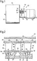
- the abradable structure 59 of the seals 48 and 50 in its manufactured condition is shown more clearly in figure 3 , and comprises an open cell metallic foam 60.
- the open cell metallic foam 60 is bonded to the substrate 58 of the shrouds 54 and/or the platforms 56.
- the open cell metallic foam 60 has a first region 62 and a second region 64.
- the first region 62 of the open cell metallic foam 60 is arranged adjacent to the substrate 58 of the shrouds 54 and/or the platforms 56 and the second region 64 of the open cell metallic foam 60 is spaced from the substrate 58 of the shrouds 54 and/or the platforms 56 by the first region 62 of the open cell metallic foam 60.
- the pores 68 of the second region 64 of the open cell metallic foam 60 are filled with an abradable material 70 and the pores 66 of the first region 62 of the open cell metallic foam 60 do not contain an abradable material and are empty, except for any contained gas or air.
- a layer of abradable material 72 is deposited on the second region 64 of the open cell metallic foam 60.
- the open cell metallic foam 60 is initially bonded to the substrate 58 of the shroud 54 and/or platform 56 and preferably this is by brazing.
- the open cell metallic foam 60 has a uniform density.
- a temporary filler is provided in the first region 62 of the open cell metallic foam 60 to ensure the pores 66 of the first region 64 of the open cell metallic foam 60 are not filled with an abradable material 70, e.g. they remain empty except for gas or air.
- the temporary filler is removed after the pores 68 of the second region 64 of the open cell metallic foam 60 have been filled with the abradable material 70.
- the temporary filler may be wax and the wax is removed by melting the wax.
- the temporary filler may be a water soluble material, e.g. Aquapour (RTM) and the water soluble material is removed by dissolving the water soluble material.
- RTM Aquapour
- the temporary filler in the pores 66 in the first region 62 of the open cell metallic foam 60 it may be necessary to drill a hole through the substrate 58 of the shroud 54.
- the open cell metallic foam 60 has a graded density, e.g. the pores 66 in the first region 62 of the open cell metallic foam 60 are smaller than the pores 68 in the second region 64 of the open cell metallic foam 60.
- the fact that the pores 66 in the first region 62 of the open cell metallic foam 60 are smaller than the pores 68 in the second region 64 ensures that the pores 66 in the first region 64 are not filled with the abradable material 70.
- the pores 66, 68 of the open cell metallic foam 60 have dimensions of 1.0mm to 1.25mm and the thickness of the walls of the open cell metallic foam 60 is less than 0.25mm.
- abradable materials 70, 72 may be used for the seal 48, 50 depending upon the application, for example the abradable material may comprise a polymer, a metal or a ceramic.
- the abradable material 70, 72 comprises a polymer and the polymer may comprise silicone rubber or syntactic silicone rubber containing hollow spheres, e.g. hollow glass spheres.
- the polymer is filled into the pores 68 of the second region 64 of the open cell metallic foam 60 by infiltration, e.g. by brushing or spraying.
- the abradable material 70, 72 comprises a metal and the abradable material 70, 72 comprises aluminium, silicon and a polymer, e.g. polyester.
- Such an abradable material is known as Metco 601 (RTM) and is available from Sulzer Metco.
- the abradable material 70, 72 comprises a metal and the abradable material 70, 72 comprises aluminium, silicon and boron nitride.
- Such an abradable material is known as Metco 320 (RTM) and is available from Sulzer Metco.
- the abradable material 70, 72 comprises a metal
- the abradable material 70, 72 comprises MCrAlY and bentonite, clay, where M is one or more of nickel, cobalt and iron and Cr is chromium, Al is aluminium and Y is yttrium.
- M is one or more of nickel, cobalt and iron and Cr is chromium
- Al is aluminium
- Y is yttrium.
- abradable material is known as Metco 314 (RTM) and is available from Sulzer Metco.
- RTM Metco 314
- These metal based abradable materials 70, 72 are filled into the pores 68 of the second region 64 of the open cell metallic foam 60 by plasma spraying or thermal spraying.
- the abradable material 70, 72 comprises a ceramic
- the abradable material 70, 72 comprises zirconia, alumina or magnesium aluminate spinel. These ceramics are filled into the pores 68 of the second region 64 of the open cell metallic foam 60 by plasma spraying or thermal spraying.
- the open cell metallic foam 60 comprises nickel or a nickel alloy, more preferably a nickel chromium alloy.
- the open cell metallic foam 60 is preferably manufactured by electroplating a polymer foam and then removing the polymer foam.
- the substrate 58 of the shroud 54 or platform 56 comprises a metal and comprises nickel, a nickel alloy, steel, titanium or a titanium alloy.
- the open cell metallic foam 60 has better mechanical integrity and abradability properties than current thermally sprayed abradable coatings, due to a high metal to pore ratio of the open cell metallic foam 60 which allows the open cell metallic foam 60 to collapse, and/or deform during rubbing and this reduces temperatures at the rubbing interface. Conversely the open cell metallic foam 60 exhibits poor sealing properties due to the free flow of gas through the pores of the open cell metallic foam 60.
- the present invention provides a second region 64 of the open cell metallic foam 60 in which the pores 68 are filled with an abradable material 70 and a first region 62 of the open cell metallic foam 60 in which the pores 66 are not filled with abradable material or are empty.
- a layer of abradable material 72 is provided on the second region 64 of the open cell metallic foam 60.
- the tips 44 of the compressor rotor blades 26 cut/rub a track 74 through the layer of abradable material 72 on the shroud 54, or the fins 46 cut a track 74 through the layer of abradable material 72 on the platform 56, as shown in figure 4 .
- the abradable material 70 in the region 64 of the open cell metallic foam 60 transfers the loads generated during the cutting/rubbing process to a larger surface area, over the full axial width of the seal 48, 50, than without the abradable material 70. This helps disperse the energy at the cut/rub interface and reduces the temperature at the cut/rub interface.
- the first region 62 of the open cell metallic foam 60 is able to collapse and/or deform in operation during rubbing/cutting and absorbs energy from the rubbing/cutting and this reduces temperatures at the rub/cut interface, as shown in figure 4 .
- the first region 62 of the open cell metallic foam 60 is compliant and the inherent strain tolerance of the open cell metallic foam is able to absorb any cyclic thermal fatigue due to the difference in coefficients of thermal expansion between the abradable material 70, 72 and the substrate 58 of the shroud 54 or platform 56.
- the collapsing/deforming of the first region 62 of the open cell metallic foam 60 also reduces the amount of debris, e.g. abradable material 72, released as the track is cut in the abradable material 72.
- the first region 62 of the open cell metallic foam 60 acts as a thermal and acoustic insulator.
- the present invention is also applicable to a fan casing shroud or a compressor casing shroud which has a casing treatment, e.g. a plurality of circumferentially spaced slots provided in the casing to improve the surge margin of the fan or compressor.
- Figure 5 shows a perspective view of a seal 48 with a slot 80 in the abradable structure 59.
- the abradable structure 59 is substantially the same as that described with reference to figures 3 and 4 .
Landscapes
- Engineering & Computer Science (AREA)
- General Engineering & Computer Science (AREA)
- Mechanical Engineering (AREA)
- Structures Of Non-Positive Displacement Pumps (AREA)
- Turbine Rotor Nozzle Sealing (AREA)
Claims (18)
- Dichtung (48) zwischen einem ersten und zweiten relativ beweglichen Element (26, 28), wobei die Dichtung (48) eine abreibbare Struktur (59) an mindestens einem (28) der relativ beweglichen Elemente (26, 28) umfasst, wobei die abreibbare Struktur (59) einen metallischen Schaum (60) umfasst, der Poren (66, 68) aufweist, dadurch gekennzeichnet, dass der metallische Schaum (60) eine erste Region (62) und eine zweite Region (64) aufweist, wobei die erste Region (62) des metallischen Schaums (60) neben dem mindestens einen (28) von den relativ beweglichen Elementen (26, 28) angeordnet ist, die zweite Region (64) des metallischen Schaums (60) durch die erste Region (62) des metallischen Schaums (60) von dem mindestens einen (28) der relativ beweglichen Elemente (26, 28) beabstandet ist, die Poren (68) der zweiten Region (64) des metallischen Schaums (60) ein abreibbares Material (70) enthalten und die Poren (66) der ersten Region (62) des metallischen Schaums (60) kein abreibbares Material enthalten und eine Schicht aus abreibbarem Material (72) an der zweiten Region (64) des metallischen Schaums (60) angeordnet ist.
- Dichtung nach Anspruch 1, wobei der metallische Schaum (60) an das mindestens eine (28) der relativ beweglichen Elemente (26, 28) gebunden ist.
- Dichtung nach Anspruch 2, wobei der metallische Schaum (60) an das mindestens eine (28) der relativ beweglichen Elemente (26, 28) gelötet ist.
- Dichtung nach einem der Ansprüche 1 bis 3, wobei der metallische Schaum (60) eine einheitliche Dichte aufweist oder der metallische Schaum (60) eine abgestufte Dichte aufweist und die Poren (66) in der ersten Region (62) des metallischen Schaums (60) kleiner als die Poren (68) in der zweiten Region (64) des metallischen Schaums (60) sind.
- Dichtung nach einem der Ansprüche 1 bis 4, wobei die Poren (66, 68) des metallischen Schaums (60) Abmessungen von 1,0 mm bis 1,25 mm aufweisen und die Dicke der Wände des metallischen Schaums (60) weniger als 0,25 mm ist.
- Dichtung nach einem der Ansprüche 1 bis 5, wobei das abreibbare Material (70) ein Polymer, ein Metall oder ein keramisches Material umfasst, wobei das Polymer Silikonkautschuk oder syntaktischen Silikonkautschuk, der Hohlkugeln enthält, umfasst, das Metall Aluminium, Silizium und ein Polymer, Aluminium-, Silizium- und Bornitrid oder ein MCrAlY und Bentonit umfasst, wobei M eines oder mehrere von Nickel, Cobalt und Eisen ist und Cr Chrom ist, Al Aluminium ist und Y Yttrium ist, das keramische Material Zirkonoxid, Aluminiumoxid oder Magnesiumaluminatspinell umfasst.
- Dichtung nach einem der Ansprüche 1 bis 6, wobei der metallische Schaum (60) Nickel, eine Nickellegierung oder eine Nickel-Chrom-Legierung umfasst.
- Dichtung nach einem der Ansprüche 1 bis 7, wobei das mindestens eine (28) der relativ beweglichen Elemente (26, 28) Nickel, eine Nickellegierung, Stahl, Titan oder eine Titanlegierung umfasst.
- Dichtung nach einem der Ansprüche 1 bis 8, wobei das mindestens eine (28) der relativ beweglichen Elemente (26, 28) eine Komponente eines Gasturbinenmotors (10) ist.
- Dichtung nach Anspruch 9, wobei die Komponente eine Verdichterummantelung oder eine Turbinenummantelung ist.
- Verfahren zur Herstellung einer Dichtung (48) zwischen einer ersten und zweiten relativ beweglichen Komponente (26, 28), wobei das Verfahren das Binden eines metallischen Schaums (60) an mindestens eines (28) der relativ beweglichen Elemente (26, 28), wobei der metallische Schaum (60) eine erste Region (62) und eine zweite Region (64) aufweist, wobei die erste Region (62) des metallischen Schaums (60) neben der mindestens einen (28) der relativ beweglichen Komponenten (26, 28) angeordnet ist, die zweite Region (64) des metallischen Schaums (60) durch die erste Region (62) des metallischen Schaums (60) von dem mindestens einen (28) der relativ beweglichen Elemente (26, 28) beabstandet ist, das Füllen der Poren (68) der zweiten Region (64) des metallischen Schaums (60) mit einem abreibbaren Material (70) und das Sicherstellen, dass die Poren (66) der ersten Region (62) des metallischen Schaums (60) kein abreibbares Material enthalten, und das Abscheiden einer Schicht aus abreibbarem Material (72) an der zweiten Region (64) des metallischen Schaums (60) umfasst.
- Verfahren nach Anspruch 11, wobei der metallische Schaum eine einheitliche Dichte aufweist, die eine temporäre Füllung in der ersten Region (62) bereitstellt, um sicherzustellen, dass die Poren (66) der ersten Region (62) des metallischen Schaums (60) kein abreibbares Material enthalten, wobei die temporäre Füllung entfernt wird, nachdem die Poren (68) der zweiten Region (64) des metallischen Schaums (60) mit einem abreibbaren Material (70) gefüllt worden sind.
- Verfahren nach Anspruch 12, wobei die temporäre Füllung Wachs umfasst und das Wachs entfernt wird, indem das Wachs geschmolzen wird, oder die temporäre Füllung ein wasserlösliches Material umfasst und das wasserlösliche Material durch Auflösen des wasserlöslichen Materials entfernt wird.
- Verfahren nach einem der Ansprüche 11 bis 13, wobei das abreibbare Material (70) ein Polymer, ein Metall oder ein keramisches Material umfasst, wobei das Polymer Silikonkautschuk oder syntaktischen Silikonkautschuk, der Hohlkugeln enthält, umfasst, das Metall Aluminium, Silizium und ein Polymer, Aluminium-, Silizium- und Bornitrid oder ein MCrAlY und Bentonit umfasst, wobei M eines oder mehrere von Nickel, Cobalt und Eisen ist und Cr Chrom ist, Al Aluminium ist und Y Yttrium ist, das keramische Material Zirkonoxid, Aluminiumoxid oder Magnesiumaluminatspinell umfasst.
- Verfahren nach Anspruch 14, umfassend das Füllen der Poren (68) der zweiten Region (64) des metallischen Schaums (60) durch Infiltrieren, Bürsten oder Spritzen des Polymers.
- Verfahren nach Anspruch 14, umfassend Plasmaspritzen oder thermisches Spritzen des Metalls oder keramischen Materials in die Poren (68) der zweiten Region (64) des metallischen Schaums (60).
- Verfahren nach einem der Ansprüche 11 bis 16, wobei der metallische Schaum (60) Nickel, eine Nickellegierung oder eine Nickel-Chrom-Legierung umfasst.
- Verfahren nach einem der Ansprüche 11 bis 17, wobei die mindestens eine der relativ beweglichen Komponenten (26, 28) Nickel, eine Nickellegierung, Stahl, Titan oder eine Titanlegierung umfasst.
Applications Claiming Priority (1)
| Application Number | Priority Date | Filing Date | Title |
|---|---|---|---|
| GBGB0822416.4A GB0822416D0 (en) | 2008-12-10 | 2008-12-10 | A seal and a method of manufacturing a seal |
Publications (3)
| Publication Number | Publication Date |
|---|---|
| EP2196632A2 EP2196632A2 (de) | 2010-06-16 |
| EP2196632A3 EP2196632A3 (de) | 2012-12-05 |
| EP2196632B1 true EP2196632B1 (de) | 2018-05-16 |
Family
ID=40289714
Family Applications (1)
| Application Number | Title | Priority Date | Filing Date |
|---|---|---|---|
| EP09252387.7A Not-in-force EP2196632B1 (de) | 2008-12-10 | 2009-10-08 | Dichtung sowie Verfahren zur Herstellung einer Dichtung in einer Gasturbine |
Country Status (3)
| Country | Link |
|---|---|
| US (1) | US8650753B2 (de) |
| EP (1) | EP2196632B1 (de) |
| GB (1) | GB0822416D0 (de) |
Families Citing this family (45)
| Publication number | Priority date | Publication date | Assignee | Title |
|---|---|---|---|---|
| DE102009034025A1 (de) * | 2009-07-21 | 2011-01-27 | Mtu Aero Engines Gmbh | Einlaufbelag zur Anordnung an einem Gasturbinenbauteil |
| JP5484990B2 (ja) * | 2010-03-30 | 2014-05-07 | 三菱重工業株式会社 | タービン |
| JP5574825B2 (ja) * | 2010-05-26 | 2014-08-20 | 三菱重工業株式会社 | シール構造、これを備えたタービン機械およびこれを備えた発電プラント |
| EP2410133A1 (de) * | 2010-07-22 | 2012-01-25 | Siemens Aktiengesellschaft | Gasturbine und Verfahren zum Abdichten von Leckströmen in einer solchen |
| US9249887B2 (en) | 2010-08-03 | 2016-02-02 | Dresser-Rand Company | Low deflection bi-metal rotor seals |
| GB2483060B (en) * | 2010-08-23 | 2013-05-15 | Rolls Royce Plc | A turbomachine casing assembly |
| US8770927B2 (en) | 2010-10-25 | 2014-07-08 | United Technologies Corporation | Abrasive cutter formed by thermal spray and post treatment |
| US8770926B2 (en) | 2010-10-25 | 2014-07-08 | United Technologies Corporation | Rough dense ceramic sealing surface in turbomachines |
| US8936432B2 (en) | 2010-10-25 | 2015-01-20 | United Technologies Corporation | Low density abradable coating with fine porosity |
| US9169740B2 (en) | 2010-10-25 | 2015-10-27 | United Technologies Corporation | Friable ceramic rotor shaft abrasive coating |
| US8790078B2 (en) | 2010-10-25 | 2014-07-29 | United Technologies Corporation | Abrasive rotor shaft ceramic coating |
| GB2489693B (en) * | 2011-04-04 | 2014-10-01 | Rolls Royce Plc | Abradable liner |
| US20130017070A1 (en) * | 2011-07-13 | 2013-01-17 | General Electric Company | Turbine seal, turbine, and process of fabricating a turbine seal |
| US20130017071A1 (en) * | 2011-07-13 | 2013-01-17 | General Electric Company | Foam structure, a process of fabricating a foam structure and a turbine including a foam structure |
| FR2979664B1 (fr) * | 2011-09-01 | 2017-10-13 | Snecma | Paroi stator de turbomachine recouverte d'un revetement abradable a faible rugosite aerodynamique |
| US9938844B2 (en) * | 2011-10-26 | 2018-04-10 | General Electric Company | Metallic stator seal |
| EP2607715B1 (de) * | 2011-12-22 | 2017-03-29 | MTU Aero Engines GmbH | Gehäuse für einen beschaufelten Rotor einer Strömungsmaschine |
| US10161523B2 (en) | 2011-12-23 | 2018-12-25 | General Electric Company | Enhanced cloth seal |
| EP2647798B1 (de) * | 2012-04-04 | 2015-09-16 | MTU Aero Engines AG | Verfahren zur Herstellung eines Einlaufbelags |
| ES2700788T3 (es) | 2012-04-04 | 2019-02-19 | MTU Aero Engines AG | Sistema de sellado para una turbomáquina |
| FR2994397B1 (fr) | 2012-08-07 | 2014-08-01 | Snecma | Revetement en materiau abradable a faible rugosite de surface |
| US10065243B2 (en) | 2012-10-01 | 2018-09-04 | United Technologies Corporation | Aluminum based abradable material with reduced metal transfer to blades |
| ITMI20121806A1 (it) * | 2012-10-24 | 2014-04-25 | Exergy Spa | Metodo per costruire stadi di turbine radiali centrifughe |
| US10301949B2 (en) * | 2013-01-29 | 2019-05-28 | United Technologies Corporation | Blade rub material |
| EP2971608B1 (de) * | 2013-03-15 | 2020-06-10 | United Technologies Corporation | Gasturbinenmotor und verfahren zur herstellung |
| DE102013212465B4 (de) | 2013-06-27 | 2015-03-12 | MTU Aero Engines AG | Dichtanordnung für eine Strömungsmaschine, eine Leitschaufelanordnung und eine Strömungsmaschine mit einer derartigen Dichtanordnung |
| US20160215646A1 (en) * | 2013-09-06 | 2016-07-28 | General Electric Company | Gas turbine laminate seal assembly comprising first and second honeycomb layer and a perforated intermediate seal plate in-between |
| DE102013223585A1 (de) | 2013-11-19 | 2015-06-03 | MTU Aero Engines AG | Einlaufbelag auf Basis von Metallfasern |
| GB201403588D0 (en) | 2014-02-28 | 2014-04-16 | Rolls Royce Plc | Blade tip |
| DE102014208801A1 (de) * | 2014-05-09 | 2015-11-12 | MTU Aero Engines AG | Dichtung, Verfahren zur Herstellung einer Dichtung und Strömungsmaschine |
| US10036402B2 (en) * | 2014-05-14 | 2018-07-31 | United Technologies Corporation | Max phase reinforced polymer matrix composite abradables with enhanced thermal conductivity |
| US10030532B2 (en) | 2015-04-22 | 2018-07-24 | United Technologies Corporation | Abradable seal with thermally conductive microspheres |
| US9951632B2 (en) | 2015-07-23 | 2018-04-24 | Honeywell International Inc. | Hybrid bonded turbine rotors and methods for manufacturing the same |
| FR3040461B1 (fr) | 2015-09-02 | 2018-02-23 | Safran Aircraft Engines | Element de joint d'etancheite a labyrinthe pour turbine |
| US10247027B2 (en) | 2016-03-23 | 2019-04-02 | United Technologies Corporation | Outer airseal insulated rub strip |
| US10669878B2 (en) * | 2016-03-23 | 2020-06-02 | Raytheon Technologies Corporation | Outer airseal abradable rub strip |
| US10267174B2 (en) | 2016-04-28 | 2019-04-23 | United Technologies Corporation | Outer airseal abradable rub strip |
| US20180050422A1 (en) * | 2016-08-19 | 2018-02-22 | Solar Turbines Incorporated | Method for manufacturing compressor components |
| US10900371B2 (en) | 2017-07-27 | 2021-01-26 | Rolls-Royce North American Technologies, Inc. | Abradable coatings for high-performance systems |
| US10858950B2 (en) | 2017-07-27 | 2020-12-08 | Rolls-Royce North America Technologies, Inc. | Multilayer abradable coatings for high-performance systems |
| US10533610B1 (en) * | 2018-05-01 | 2020-01-14 | Florida Turbine Technologies, Inc. | Gas turbine engine fan stage with bearing cooling |
| US10808565B2 (en) * | 2018-05-22 | 2020-10-20 | Rolls-Royce Plc | Tapered abradable coatings |
| US11674396B2 (en) | 2021-07-30 | 2023-06-13 | General Electric Company | Cooling air delivery assembly |
| US11674405B2 (en) | 2021-08-30 | 2023-06-13 | General Electric Company | Abradable insert with lattice structure |
| GB202401942D0 (en) * | 2024-02-13 | 2024-03-27 | Rolls Royce Plc | A thermal barrier structure and coating |
Family Cites Families (15)
| Publication number | Priority date | Publication date | Assignee | Title |
|---|---|---|---|---|
| US3350178A (en) * | 1963-05-14 | 1967-10-31 | Wall Colmonoy Corp | Sealing device |
| US3547455A (en) * | 1969-05-02 | 1970-12-15 | Gen Electric | Rotary seal including organic abradable material |
| US4071932A (en) * | 1976-10-28 | 1978-02-07 | Standaart Adrian W | Method of making electron guns for cathode ray tubes and the like |
| US4257735A (en) | 1978-12-15 | 1981-03-24 | General Electric Company | Gas turbine engine seal and method for making same |
| EP0187612B1 (de) | 1984-12-24 | 1990-09-12 | United Technologies Corporation | Abschleifbare Dichtung mit besonderem Erosionswiderstand |
| US5080934A (en) * | 1990-01-19 | 1992-01-14 | Avco Corporation | Process for making abradable hybrid ceramic wall structures |
| US5350557A (en) | 1991-09-23 | 1994-09-27 | Technetics Corp. | Impermeable, abradable seal and method for the production thereof |
| US5388959A (en) | 1993-08-23 | 1995-02-14 | General Electric Company | Seal including a non-metallic abradable material |
| DE19858031A1 (de) | 1998-12-16 | 2000-06-21 | Rolls Royce Deutschland | Anstreifdichtung zwischen einem Wandabschnitt und den Schaufelspitzen einer Gasturbine |
| US6547455B1 (en) * | 1999-10-18 | 2003-04-15 | Nippon Sheet Glass Co., Ltd. | Optical module for a semiconductor light-emitting device |
| DE10024302A1 (de) | 2000-05-17 | 2001-11-22 | Alstom Power Nv | Verfahren zur Herstellung eines thermisch belasteten Gussteils |
| FR2829524B1 (fr) * | 2001-09-11 | 2004-03-05 | Snecma Moteurs | Procede de realisation de parties d'extremite radiales de pieces mobiles de turbomachines |
| US6916529B2 (en) | 2003-01-09 | 2005-07-12 | General Electric Company | High temperature, oxidation-resistant abradable coatings containing microballoons and method for applying same |
| DE10360164A1 (de) | 2003-12-20 | 2005-07-21 | Mtu Aero Engines Gmbh | Gasturbinenbauteil |
| GB0613715D0 (en) | 2006-07-11 | 2006-08-23 | Rolls Royce Plc | A seal between relatively moveable members |
-
2008
- 2008-12-10 GB GBGB0822416.4A patent/GB0822416D0/en not_active Ceased
-
2009
- 2009-10-08 US US12/588,250 patent/US8650753B2/en not_active Expired - Fee Related
- 2009-10-08 EP EP09252387.7A patent/EP2196632B1/de not_active Not-in-force
Non-Patent Citations (1)
| Title |
|---|
| None * |
Also Published As
| Publication number | Publication date |
|---|---|
| GB0822416D0 (en) | 2009-01-14 |
| EP2196632A2 (de) | 2010-06-16 |
| EP2196632A3 (de) | 2012-12-05 |
| US20100143103A1 (en) | 2010-06-10 |
| US8650753B2 (en) | 2014-02-18 |
Similar Documents
| Publication | Publication Date | Title |
|---|---|---|
| EP2196632B1 (de) | Dichtung sowie Verfahren zur Herstellung einer Dichtung in einer Gasturbine | |
| EP1878876B1 (de) | Abreibbare Dichtungsschicht einer Gasturbine sowie Verfahren zu deren Herstellung | |
| JP6247815B2 (ja) | セラミックマトリックス複合材の形成方法及びセラミックマトリックス複合材部品 | |
| CN106481370B (zh) | 用于涡轮机的涂布的密封槽口系统及其形成方法 | |
| CN106979039B (zh) | 用于cmc护罩的可磨损合成物和方法 | |
| US10392958B2 (en) | Hybrid blade outer air seal for gas turbine engine | |
| CN109424369B (zh) | 包括涂层系统的涡轮叶片和形成涡轮叶片的方法 | |
| JP6340010B2 (ja) | ターボ機械の中で使用するためのシールシステムおよびそれを製作する方法 | |
| CN101148993B (zh) | 用于制作涡轮发动机的方法和设备 | |
| US8876481B2 (en) | Turbine airfoil component assembly for use in a gas turbine engine and methods for fabricating same | |
| EP3498976B1 (de) | Turbomaschinenschaufel mit strömungsweg-oberflächenrippen | |
| JP2006036632A (ja) | 7FA+e第1段アブレイダブル被膜及びその作製方法 | |
| EP2196631A2 (de) | Komponente mit einer Schleifschicht und Verfahren zur Aufbringung einer Schleifschicht auf eine Komponente | |
| JP6313762B2 (ja) | 低表面粗度を有する材料からなる摩耗性コーティング | |
| EP3683017B1 (de) | Schleifbeschichtung für mechanische hochtemperatursysteme und mechanische hochtemperatursysteme mit einer schleifbeschichtung | |
| US11555419B2 (en) | Cost effective manufacturing method for GSAC incorporating a stamped preform | |
| JP6947851B2 (ja) | スキーラ先端を備えるタービンブレードおよび高密度酸化物分散強化層 | |
| EP2143885A1 (de) | Gasunterstützte Turbinendichtung | |
| EP4729743A1 (de) | Äusserste abrasive turbinenschaufelschicht mit abgestuften keramiken | |
| JP2026075052A (ja) | 傾斜セラミックを使用したタービンブレード最外研磨層 |
Legal Events
| Date | Code | Title | Description |
|---|---|---|---|
| PUAI | Public reference made under article 153(3) epc to a published international application that has entered the european phase |
Free format text: ORIGINAL CODE: 0009012 |
|
| AK | Designated contracting states |
Kind code of ref document: A2 Designated state(s): AT BE BG CH CY CZ DE DK EE ES FI FR GB GR HR HU IE IS IT LI LT LU LV MC MK MT NL NO PL PT RO SE SI SK SM TR |
|
| AX | Request for extension of the european patent |
Extension state: AL BA RS |
|
| PUAL | Search report despatched |
Free format text: ORIGINAL CODE: 0009013 |
|
| AK | Designated contracting states |
Kind code of ref document: A3 Designated state(s): AT BE BG CH CY CZ DE DK EE ES FI FR GB GR HR HU IE IS IT LI LT LU LV MC MK MT NL NO PL PT RO SE SI SK SM TR |
|
| AX | Request for extension of the european patent |
Extension state: AL BA RS |
|
| RIC1 | Information provided on ipc code assigned before grant |
Ipc: F01D 11/12 20060101AFI20121026BHEP |
|
| 17P | Request for examination filed |
Effective date: 20130423 |
|
| RAP1 | Party data changed (applicant data changed or rights of an application transferred) |
Owner name: ROLLS-ROYCE PLC |
|
| GRAP | Despatch of communication of intention to grant a patent |
Free format text: ORIGINAL CODE: EPIDOSNIGR1 |
|
| STAA | Information on the status of an ep patent application or granted ep patent |
Free format text: STATUS: GRANT OF PATENT IS INTENDED |
|
| INTG | Intention to grant announced |
Effective date: 20180103 |
|
| GRAS | Grant fee paid |
Free format text: ORIGINAL CODE: EPIDOSNIGR3 |
|
| GRAA | (expected) grant |
Free format text: ORIGINAL CODE: 0009210 |
|
| STAA | Information on the status of an ep patent application or granted ep patent |
Free format text: STATUS: THE PATENT HAS BEEN GRANTED |
|
| AK | Designated contracting states |
Kind code of ref document: B1 Designated state(s): AT BE BG CH CY CZ DE DK EE ES FI FR GB GR HR HU IE IS IT LI LT LU LV MC MK MT NL NO PL PT RO SE SI SK SM TR |
|
| REG | Reference to a national code |
Ref country code: GB Ref legal event code: FG4D |
|
| REG | Reference to a national code |
Ref country code: CH Ref legal event code: EP |
|
| REG | Reference to a national code |
Ref country code: IE Ref legal event code: FG4D |
|
| REG | Reference to a national code |
Ref country code: DE Ref legal event code: R096 Ref document number: 602009052296 Country of ref document: DE |
|
| REG | Reference to a national code |
Ref country code: AT Ref legal event code: REF Ref document number: 999773 Country of ref document: AT Kind code of ref document: T Effective date: 20180615 |
|
| REG | Reference to a national code |
Ref country code: NL Ref legal event code: MP Effective date: 20180516 |
|
| REG | Reference to a national code |
Ref country code: LT Ref legal event code: MG4D |
|
| REG | Reference to a national code |
Ref country code: FR Ref legal event code: PLFP Year of fee payment: 10 |
|
| PG25 | Lapsed in a contracting state [announced via postgrant information from national office to epo] |
Ref country code: FI Free format text: LAPSE BECAUSE OF FAILURE TO SUBMIT A TRANSLATION OF THE DESCRIPTION OR TO PAY THE FEE WITHIN THE PRESCRIBED TIME-LIMIT Effective date: 20180516 Ref country code: BG Free format text: LAPSE BECAUSE OF FAILURE TO SUBMIT A TRANSLATION OF THE DESCRIPTION OR TO PAY THE FEE WITHIN THE PRESCRIBED TIME-LIMIT Effective date: 20180816 Ref country code: LT Free format text: LAPSE BECAUSE OF FAILURE TO SUBMIT A TRANSLATION OF THE DESCRIPTION OR TO PAY THE FEE WITHIN THE PRESCRIBED TIME-LIMIT Effective date: 20180516 Ref country code: ES Free format text: LAPSE BECAUSE OF FAILURE TO SUBMIT A TRANSLATION OF THE DESCRIPTION OR TO PAY THE FEE WITHIN THE PRESCRIBED TIME-LIMIT Effective date: 20180516 Ref country code: SE Free format text: LAPSE BECAUSE OF FAILURE TO SUBMIT A TRANSLATION OF THE DESCRIPTION OR TO PAY THE FEE WITHIN THE PRESCRIBED TIME-LIMIT Effective date: 20180516 Ref country code: NO Free format text: LAPSE BECAUSE OF FAILURE TO SUBMIT A TRANSLATION OF THE DESCRIPTION OR TO PAY THE FEE WITHIN THE PRESCRIBED TIME-LIMIT Effective date: 20180816 |
|
| PG25 | Lapsed in a contracting state [announced via postgrant information from national office to epo] |
Ref country code: HR Free format text: LAPSE BECAUSE OF FAILURE TO SUBMIT A TRANSLATION OF THE DESCRIPTION OR TO PAY THE FEE WITHIN THE PRESCRIBED TIME-LIMIT Effective date: 20180516 Ref country code: LV Free format text: LAPSE BECAUSE OF FAILURE TO SUBMIT A TRANSLATION OF THE DESCRIPTION OR TO PAY THE FEE WITHIN THE PRESCRIBED TIME-LIMIT Effective date: 20180516 Ref country code: GR Free format text: LAPSE BECAUSE OF FAILURE TO SUBMIT A TRANSLATION OF THE DESCRIPTION OR TO PAY THE FEE WITHIN THE PRESCRIBED TIME-LIMIT Effective date: 20180817 Ref country code: NL Free format text: LAPSE BECAUSE OF FAILURE TO SUBMIT A TRANSLATION OF THE DESCRIPTION OR TO PAY THE FEE WITHIN THE PRESCRIBED TIME-LIMIT Effective date: 20180516 |
|
| REG | Reference to a national code |
Ref country code: AT Ref legal event code: MK05 Ref document number: 999773 Country of ref document: AT Kind code of ref document: T Effective date: 20180516 |
|
| PG25 | Lapsed in a contracting state [announced via postgrant information from national office to epo] |
Ref country code: AT Free format text: LAPSE BECAUSE OF FAILURE TO SUBMIT A TRANSLATION OF THE DESCRIPTION OR TO PAY THE FEE WITHIN THE PRESCRIBED TIME-LIMIT Effective date: 20180516 Ref country code: PL Free format text: LAPSE BECAUSE OF FAILURE TO SUBMIT A TRANSLATION OF THE DESCRIPTION OR TO PAY THE FEE WITHIN THE PRESCRIBED TIME-LIMIT Effective date: 20180516 Ref country code: RO Free format text: LAPSE BECAUSE OF FAILURE TO SUBMIT A TRANSLATION OF THE DESCRIPTION OR TO PAY THE FEE WITHIN THE PRESCRIBED TIME-LIMIT Effective date: 20180516 Ref country code: CZ Free format text: LAPSE BECAUSE OF FAILURE TO SUBMIT A TRANSLATION OF THE DESCRIPTION OR TO PAY THE FEE WITHIN THE PRESCRIBED TIME-LIMIT Effective date: 20180516 Ref country code: SK Free format text: LAPSE BECAUSE OF FAILURE TO SUBMIT A TRANSLATION OF THE DESCRIPTION OR TO PAY THE FEE WITHIN THE PRESCRIBED TIME-LIMIT Effective date: 20180516 Ref country code: EE Free format text: LAPSE BECAUSE OF FAILURE TO SUBMIT A TRANSLATION OF THE DESCRIPTION OR TO PAY THE FEE WITHIN THE PRESCRIBED TIME-LIMIT Effective date: 20180516 Ref country code: DK Free format text: LAPSE BECAUSE OF FAILURE TO SUBMIT A TRANSLATION OF THE DESCRIPTION OR TO PAY THE FEE WITHIN THE PRESCRIBED TIME-LIMIT Effective date: 20180516 |
|
| REG | Reference to a national code |
Ref country code: DE Ref legal event code: R097 Ref document number: 602009052296 Country of ref document: DE |
|
| PG25 | Lapsed in a contracting state [announced via postgrant information from national office to epo] |
Ref country code: SM Free format text: LAPSE BECAUSE OF FAILURE TO SUBMIT A TRANSLATION OF THE DESCRIPTION OR TO PAY THE FEE WITHIN THE PRESCRIBED TIME-LIMIT Effective date: 20180516 Ref country code: IT Free format text: LAPSE BECAUSE OF FAILURE TO SUBMIT A TRANSLATION OF THE DESCRIPTION OR TO PAY THE FEE WITHIN THE PRESCRIBED TIME-LIMIT Effective date: 20180516 |
|
| PLBE | No opposition filed within time limit |
Free format text: ORIGINAL CODE: 0009261 |
|
| STAA | Information on the status of an ep patent application or granted ep patent |
Free format text: STATUS: NO OPPOSITION FILED WITHIN TIME LIMIT |
|
| 26N | No opposition filed |
Effective date: 20190219 |
|
| PG25 | Lapsed in a contracting state [announced via postgrant information from national office to epo] |
Ref country code: SI Free format text: LAPSE BECAUSE OF FAILURE TO SUBMIT A TRANSLATION OF THE DESCRIPTION OR TO PAY THE FEE WITHIN THE PRESCRIBED TIME-LIMIT Effective date: 20180516 |
|
| REG | Reference to a national code |
Ref country code: CH Ref legal event code: PL |
|
| REG | Reference to a national code |
Ref country code: BE Ref legal event code: MM Effective date: 20181031 |
|
| PG25 | Lapsed in a contracting state [announced via postgrant information from national office to epo] |
Ref country code: LU Free format text: LAPSE BECAUSE OF NON-PAYMENT OF DUE FEES Effective date: 20181008 Ref country code: MC Free format text: LAPSE BECAUSE OF FAILURE TO SUBMIT A TRANSLATION OF THE DESCRIPTION OR TO PAY THE FEE WITHIN THE PRESCRIBED TIME-LIMIT Effective date: 20180516 |
|
| REG | Reference to a national code |
Ref country code: IE Ref legal event code: MM4A |
|
| PG25 | Lapsed in a contracting state [announced via postgrant information from national office to epo] |
Ref country code: LI Free format text: LAPSE BECAUSE OF NON-PAYMENT OF DUE FEES Effective date: 20181031 Ref country code: CH Free format text: LAPSE BECAUSE OF NON-PAYMENT OF DUE FEES Effective date: 20181031 Ref country code: BE Free format text: LAPSE BECAUSE OF NON-PAYMENT OF DUE FEES Effective date: 20181031 |
|
| PG25 | Lapsed in a contracting state [announced via postgrant information from national office to epo] |
Ref country code: IE Free format text: LAPSE BECAUSE OF NON-PAYMENT OF DUE FEES Effective date: 20181008 |
|
| PG25 | Lapsed in a contracting state [announced via postgrant information from national office to epo] |
Ref country code: MT Free format text: LAPSE BECAUSE OF NON-PAYMENT OF DUE FEES Effective date: 20181008 |
|
| PG25 | Lapsed in a contracting state [announced via postgrant information from national office to epo] |
Ref country code: TR Free format text: LAPSE BECAUSE OF FAILURE TO SUBMIT A TRANSLATION OF THE DESCRIPTION OR TO PAY THE FEE WITHIN THE PRESCRIBED TIME-LIMIT Effective date: 20180516 |
|
| PG25 | Lapsed in a contracting state [announced via postgrant information from national office to epo] |
Ref country code: PT Free format text: LAPSE BECAUSE OF FAILURE TO SUBMIT A TRANSLATION OF THE DESCRIPTION OR TO PAY THE FEE WITHIN THE PRESCRIBED TIME-LIMIT Effective date: 20180516 |
|
| PG25 | Lapsed in a contracting state [announced via postgrant information from national office to epo] |
Ref country code: HU Free format text: LAPSE BECAUSE OF FAILURE TO SUBMIT A TRANSLATION OF THE DESCRIPTION OR TO PAY THE FEE WITHIN THE PRESCRIBED TIME-LIMIT; INVALID AB INITIO Effective date: 20091008 Ref country code: MK Free format text: LAPSE BECAUSE OF NON-PAYMENT OF DUE FEES Effective date: 20180516 Ref country code: CY Free format text: LAPSE BECAUSE OF FAILURE TO SUBMIT A TRANSLATION OF THE DESCRIPTION OR TO PAY THE FEE WITHIN THE PRESCRIBED TIME-LIMIT Effective date: 20180516 |
|
| PG25 | Lapsed in a contracting state [announced via postgrant information from national office to epo] |
Ref country code: IS Free format text: LAPSE BECAUSE OF FAILURE TO SUBMIT A TRANSLATION OF THE DESCRIPTION OR TO PAY THE FEE WITHIN THE PRESCRIBED TIME-LIMIT Effective date: 20180916 |
|
| PGFP | Annual fee paid to national office [announced via postgrant information from national office to epo] |
Ref country code: FR Payment date: 20201027 Year of fee payment: 12 Ref country code: GB Payment date: 20201027 Year of fee payment: 12 |
|
| PGFP | Annual fee paid to national office [announced via postgrant information from national office to epo] |
Ref country code: DE Payment date: 20201228 Year of fee payment: 12 |
|
| REG | Reference to a national code |
Ref country code: DE Ref legal event code: R119 Ref document number: 602009052296 Country of ref document: DE |
|
| GBPC | Gb: european patent ceased through non-payment of renewal fee |
Effective date: 20211008 |
|
| PG25 | Lapsed in a contracting state [announced via postgrant information from national office to epo] |
Ref country code: GB Free format text: LAPSE BECAUSE OF NON-PAYMENT OF DUE FEES Effective date: 20211008 Ref country code: DE Free format text: LAPSE BECAUSE OF NON-PAYMENT OF DUE FEES Effective date: 20220503 |
|
| PG25 | Lapsed in a contracting state [announced via postgrant information from national office to epo] |
Ref country code: FR Free format text: LAPSE BECAUSE OF NON-PAYMENT OF DUE FEES Effective date: 20211031 |