EP2196733A1 - Lance de brûleur - Google Patents
Lance de brûleur Download PDFInfo
- Publication number
- EP2196733A1 EP2196733A1 EP08171526A EP08171526A EP2196733A1 EP 2196733 A1 EP2196733 A1 EP 2196733A1 EP 08171526 A EP08171526 A EP 08171526A EP 08171526 A EP08171526 A EP 08171526A EP 2196733 A1 EP2196733 A1 EP 2196733A1
- Authority
- EP
- European Patent Office
- Prior art keywords
- burner
- lance
- heat shield
- opening
- tip
- Prior art date
- Legal status (The legal status is an assumption and is not a legal conclusion. Google has not performed a legal analysis and makes no representation as to the accuracy of the status listed.)
- Withdrawn
Links
- 239000000446 fuel Substances 0.000 claims abstract description 58
- 239000012809 cooling fluid Substances 0.000 claims abstract description 12
- 238000011144 upstream manufacturing Methods 0.000 claims abstract description 3
- 239000007788 liquid Substances 0.000 claims description 15
- 230000002093 peripheral effect Effects 0.000 claims description 10
- 239000007921 spray Substances 0.000 claims description 2
- 239000012530 fluid Substances 0.000 abstract 1
- 238000001816 cooling Methods 0.000 description 18
- 239000007789 gas Substances 0.000 description 8
- 239000011324 bead Substances 0.000 description 5
- 238000004939 coking Methods 0.000 description 4
- 239000000443 aerosol Substances 0.000 description 2
- 238000002485 combustion reaction Methods 0.000 description 2
- 239000000498 cooling water Substances 0.000 description 2
- 238000011010 flushing procedure Methods 0.000 description 2
- 230000035939 shock Effects 0.000 description 2
- 230000008646 thermal stress Effects 0.000 description 2
- 230000002411 adverse Effects 0.000 description 1
- 238000000889 atomisation Methods 0.000 description 1
- 238000005219 brazing Methods 0.000 description 1
- 239000000567 combustion gas Substances 0.000 description 1
- 238000011109 contamination Methods 0.000 description 1
- 230000001419 dependent effect Effects 0.000 description 1
- 230000009977 dual effect Effects 0.000 description 1
- 230000000694 effects Effects 0.000 description 1
- 238000002347 injection Methods 0.000 description 1
- 239000007924 injection Substances 0.000 description 1
- 238000012423 maintenance Methods 0.000 description 1
- 239000000463 material Substances 0.000 description 1
- 230000035515 penetration Effects 0.000 description 1
- 238000003466 welding Methods 0.000 description 1
Images

Classifications
-
- F—MECHANICAL ENGINEERING; LIGHTING; HEATING; WEAPONS; BLASTING
- F23—COMBUSTION APPARATUS; COMBUSTION PROCESSES
- F23D—BURNERS
- F23D11/00—Burners using a direct spraying action of liquid droplets or vaporised liquid into the combustion space
- F23D11/10—Burners using a direct spraying action of liquid droplets or vaporised liquid into the combustion space the spraying being induced by a gaseous medium, e.g. water vapour
- F23D11/101—Burners using a direct spraying action of liquid droplets or vaporised liquid into the combustion space the spraying being induced by a gaseous medium, e.g. water vapour medium and fuel meeting before the burner outlet
Definitions
- the present invention relates to a burner lance, in particular a burner lance for a gas turbine burner.
- Such burning lances are used, for example, in burners which can be operated both with liquid fuel and with gaseous fuel.
- the lance for operation with the liquid fuels such as oil
- the oil flows through the lance, exits at its tip through several oil nozzles and thus fed to the combustion.
- the gaseous fuels are often injected into an air supply channel surrounding the nozzle lance.
- the lance tip is therefore usually exposed to high temperatures in the range of about 800 to 1,000 ° C. These high temperatures can lead to coking of residues of liquid fuels in the nozzle openings of the burner lance.
- a burner lance for use in a Burner especially in a gas turbine burner to provide, which helps to overcome the disadvantages mentioned.
- Another object of the invention is to provide an advantageous burner, in particular a gas turbine burner.
- the first object is achieved by a burner lance according to claim 1, the second object by a burner according to claim 9.
- the dependent claims contain advantageous embodiments of the invention.
- a burner lance according to the invention comprises a lance tip with at least one fuel nozzle surrounded by a heat shield.
- the heat shield is spaced from the lance tip so that there is a flow channel for a cooling fluid between the heat shield and the lance tip.
- the heat shield has at least one outflow opening for the cooling fluid in the flow channel.
- the heat shield has at least one upstream to the outflow and connected to a cooling fluid supply inlet.
- the fuel nozzle is arranged in the burner lance according to the invention in a projecting over the surface of the lance tip protrusion which is at least brought to an opening of the heat shield and which can protrude in particular in the opening of the heat shield.
- the at least bringing the projection to the opening in the heat shield makes it possible to use the heat shield not only in conjunction with gas nozzles, but in particular also in conjunction with atomizing nozzles for liquid fuels.
- the approach of the nozzle openings makes it possible to atomize the liquid fuel without the corresponding aerosol impinges on the heat shield in the region of the opening.
- an impact of fuel aerosol on the heat shield can be largely excluded.
- Coking can be avoided on the heat shield, which could reduce the flow cross-section of the cooling fluid channel in the heat shield on the one hand, which would adversely affect the cooling performance.
- the projection in which the at least one fuel nozzle is arranged, has a peripheral surface and the opening in the heat shield has an edge, between which there is a gap.
- the gap leads to a thermal decoupling of the heat shield from the projection, so that a transfer of heat from the heat shield to the nozzle projection can be avoided.
- the gap represents an outlet opening for the cooling fluid, so that penetration of hot combustion gases into the gap does not take place.
- the cooling fluid flowing out through the gap cools the nozzle projection, so that its temperature is kept in a moderate range.
- the projection may in particular be formed by a nozzle body containing the fuel nozzle, which is inserted into a recess in the lance tip adapted to the shape of the nozzle body.
- This embodiment makes it possible to replace the nozzle body, if in spite of the thermal decoupling of the heat shield and the cooling thermally induced damage to the projection occur. But also a replacement due to other causes, for example, to realize a different atomization profile is possible.
- the inflow opening for the cooling fluid may advantageously be arranged in a peripheral surface of the heat shield. This makes it possible to fix the heat shield over its entire circumference at its end remote from the lance tip on the lance body, which increases the stability of the arrangement.
- a burner according to the invention is equipped with a burner lance according to the invention.
- the burner lance can be used in particular for supplying a liquid fuel.
- the burner can then also be equipped with fuel nozzles for gaseous fuels.
- burner lances according to the invention and the burner according to the invention are particularly advantageous when a liquid fuel is supplied by the burner lance
- burner lances for supplying gaseous fuels can be designed according to the burner lance according to the invention, wherein the fuel nozzle then no atomizing nozzle.
- the use of the burner lance according to the invention in the burner according to the invention leads to the fact that the maintenance intervals for such a burner can be extended due to the increased service life of the burner lance, which lowers the operating costs.
- Fig. 1 shows a section of a burner with a burner lance according to the invention in a sectional view.
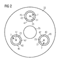
- Fig. 2 shows the burner lance of the burner Fig. 1 in a view on her front ..
- a gas turbine burner shown schematically. This has a one of a substantially cylindrical wall 1 limited air supply channel 3, in the center of a burner lance 5 runs. At the top of the burner lance fuel nozzles 7 are present for injecting a fuel into the air supplied through the air supply channel 3.
- the burner lance 5 is an oil lance for supplying a liquid fuel.
- the distribution of the fuel nozzles 7 over the circumference of the tip is in FIG. 2 to recognize, which represents a view on the front of the top.
- a second fuel supply system 9 which has an axial passage 11 through which the burner lance 5 is passed, so that only the end portion 13 of the burner lance 5 protrudes from the fuel supply system 9.
- the fuel supply system 9 is connected to swirl vanes 15 located at the downstream end of the fuel supply system 9 and extending through the air supply passage 3.
- a fuel in the present embodiment, a gaseous fuel, passed into the swirl vanes 15, from where it is injected through nozzle openings 19 in the air flowing through the air supply channel 3 air.
- the burner shown is a so-called “dual fuel burner", so a burner that can be operated with both gaseous fuels, as well as with liquid fuels.
- the invention can However, in principle, also be implemented in the context of burners in which both by the fuel supply system 9, and by the burner lance 5 each a fuel in the same state of matter is supplied, ie for example in the context of a burner in which both by the fuel supply system 9, as well a gaseous fuel is supplied through the burner lance 5 in each case.
- the burner lance 5 can be used as a pilot burner.
- the fuel nozzle 7 is designed in the present embodiment as a Zerstäubungsdüse, which is supplied via a supply channel for liquid fuels 21 to be atomized liquid fuel.
- the nozzle 7 is part of a nozzle body 23, which is inserted into a receptacle 25 in the body of the burner lance 5, which is located in the region of a frusto-conical surface 27.
- the conical surface 27 essentially forms the tip of the burner lance 5.
- the frusto-conical tip 20 is followed by a substantially cylindrical portion 29, over whose circumference an annular bead 31 extends.
- a heat shield 33 is fixed, for example by means of a welding or brazing connection, which extends from the bead 31, starting over the front part of the cylindrical portion 29 and over the lateral surface 27 of the frusto-conical portion 28.
- the end of the heat shield remote from the bead 31 has a central opening 35.
- a plurality of openings 37 - in the present embodiment three openings - present, representing the inlet openings for cooling air.
- the inflow openings 37 are distributed around the circumference of the frusto-conical portion around the circumference of the cylindrical part of the heat shield 33 located between the bead 31 and the frusto-conical portion in accordance with the distribution of the fuel nozzles 7, so that cooling air flowing in through the openings 37 flows without deflection can reach their axial flow direction to the nozzle bodies.
- a cooling air channel 39 is formed. This is supplied through the opening 37 with cooling air coming from the air supply channel 3. The cooling air then flows into the cooling air duct 39, flows around the nozzle body 23 and finally exits through the central opening 35, which forms the main exit opening for the cooling air, into the combustion chamber.
- the heat shield 33 has further openings 41 into which the nozzle bodies 23 of the fuel nozzles 7 protrude. The dimensions of the further openings 41 are selected so that the peripheral surfaces 43 of the nozzle body have a distance from the edge 45 of the openings 41.
- a gap 47 remains between the nozzle body 23 and the heat shield 33 (best seen in FIG. 2 ).
- This gap allows the outflow of a part of the cooling air flowing through the cooling air passage 39.
- the cooling air flowing out through the gap 47 cools that part of the peripheral surface 43 of the nozzle body 23 which projects into the opening 41.
- the remaining, located in the cooling air passage 39 part of this peripheral surface 43 is cooled by the main cooling air flow, which flows around the nozzle body 23 to the central outlet opening 35.
- the gap 47 also allows thermal decoupling of the nozzle body 23 from the heat shield 33, since there is no direct heat-conducting contact between the two ,
- the nozzle body 23 protrudes into the opening 41, there is when injecting a liquid fuel through a nozzle opening arranged in the end face 49 Even with a spray cone with a large opening angle, there is no risk that droplets of the atomized fuel will strike the material of the heat shield 33.
- no droplets can be entrained by the cooling air flow flowing in the cooling air duct 39 in the direction of the heat shield.
- the exiting through the gap 47 cooling air ensures that droplets that are basically on a path that would allow a hitting the edge 45 of the opening 41 are entrained by the air flow, so that the heat shield 33 reliably before a Contamination and associated possible coking is protected.
Landscapes
- Engineering & Computer Science (AREA)
- Chemical & Material Sciences (AREA)
- Combustion & Propulsion (AREA)
- Mechanical Engineering (AREA)
- General Engineering & Computer Science (AREA)
- Nozzles For Spraying Of Liquid Fuel (AREA)
Priority Applications (1)
| Application Number | Priority Date | Filing Date | Title |
|---|---|---|---|
| EP08171526A EP2196733A1 (fr) | 2008-12-12 | 2008-12-12 | Lance de brûleur |
Applications Claiming Priority (1)
| Application Number | Priority Date | Filing Date | Title |
|---|---|---|---|
| EP08171526A EP2196733A1 (fr) | 2008-12-12 | 2008-12-12 | Lance de brûleur |
Publications (1)
| Publication Number | Publication Date |
|---|---|
| EP2196733A1 true EP2196733A1 (fr) | 2010-06-16 |
Family
ID=40626945
Family Applications (1)
| Application Number | Title | Priority Date | Filing Date |
|---|---|---|---|
| EP08171526A Withdrawn EP2196733A1 (fr) | 2008-12-12 | 2008-12-12 | Lance de brûleur |
Country Status (1)
| Country | Link |
|---|---|
| EP (1) | EP2196733A1 (fr) |
Cited By (9)
| Publication number | Priority date | Publication date | Assignee | Title |
|---|---|---|---|---|
| DE102012110506A1 (de) * | 2012-11-02 | 2014-05-08 | Webasto SE | Hochdruckzerstäubungsbrenneranordnung |
| CN107076420A (zh) * | 2014-08-14 | 2017-08-18 | 西门子公司 | 具有隔热罩的多功能燃料喷嘴 |
| JP2017525924A (ja) * | 2014-08-14 | 2017-09-07 | シーメンス アクチエンゲゼルシヤフトSiemens Aktiengesellschaft | 噴霧器配列を備える多機能燃料ノズル |
| JP2018506693A (ja) * | 2015-01-22 | 2018-03-08 | シーメンス アクチエンゲゼルシヤフトSiemens Aktiengesellschaft | スロットを有するスワーラベーンを備える燃焼器入口混合システム |
| DE102016226061A1 (de) | 2016-12-22 | 2018-06-28 | Siemens Aktiengesellschaft | Brennerspitze zum Einbau in einen Brenner mit Luftkanalsystem und Brennstoffkanalsystem und Verfahren zu deren Herstellung |
| DE102017200106A1 (de) | 2017-01-05 | 2018-07-05 | Siemens Aktiengesellschaft | Brennerspitze mit einem Luftkanalsystem und einem Brennstoffkanalsystem für einen Brenner und Verfahren zu deren Herstellung |
| DE102017200643A1 (de) | 2017-01-17 | 2018-07-19 | Siemens Aktiengesellschaft | Brennerspitze mit einer Luftkanalstruktur und einer Brennstoffkanalstruktur für einen Brenner und Verfahren zur Herstellung der Brennerspitze |
| DE102022208337A1 (de) * | 2022-08-10 | 2024-02-15 | Rolls-Royce Deutschland Ltd & Co Kg | Pilotierungsanordnung, Düsenvorrichtung, Verfahren und Gasturbinenanordnung |
| DE102023203942A1 (de) * | 2023-04-27 | 2024-10-31 | Rolls-Royce Deutschland Ltd & Co Kg | Pilotierungsanordnung für eine düsenvorrichtung sowie düsenvorrichtung und gasturbinenanordnung mit einer pilotierungsanordnung |
Citations (6)
| Publication number | Priority date | Publication date | Assignee | Title |
|---|---|---|---|---|
| US4198815A (en) * | 1975-12-24 | 1980-04-22 | General Electric Company | Central injection fuel carburetor |
| EP0638769A2 (fr) * | 1993-08-10 | 1995-02-15 | ABB Management AG | Injecteur de combustible pour des combustibles liquides et gazeux et procédé de sa mise en oeuvre |
| US5680766A (en) * | 1996-01-02 | 1997-10-28 | General Electric Company | Dual fuel mixer for gas turbine combustor |
| DE19905995A1 (de) * | 1999-02-15 | 2000-08-17 | Asea Brown Boveri | Brennstofflanze zum Eindüsen von flüssigen und/oder gasförmigen Brennstoffen in eine Brennkammer sowie Verfahren zum Betrieb einer solchen Brennstofflanze |
| US6543235B1 (en) * | 2001-08-08 | 2003-04-08 | Cfd Research Corporation | Single-circuit fuel injector for gas turbine combustors |
| US7325402B2 (en) | 2004-08-04 | 2008-02-05 | Siemens Power Generation, Inc. | Pilot nozzle heat shield having connected tangs |
-
2008
- 2008-12-12 EP EP08171526A patent/EP2196733A1/fr not_active Withdrawn
Patent Citations (6)
| Publication number | Priority date | Publication date | Assignee | Title |
|---|---|---|---|---|
| US4198815A (en) * | 1975-12-24 | 1980-04-22 | General Electric Company | Central injection fuel carburetor |
| EP0638769A2 (fr) * | 1993-08-10 | 1995-02-15 | ABB Management AG | Injecteur de combustible pour des combustibles liquides et gazeux et procédé de sa mise en oeuvre |
| US5680766A (en) * | 1996-01-02 | 1997-10-28 | General Electric Company | Dual fuel mixer for gas turbine combustor |
| DE19905995A1 (de) * | 1999-02-15 | 2000-08-17 | Asea Brown Boveri | Brennstofflanze zum Eindüsen von flüssigen und/oder gasförmigen Brennstoffen in eine Brennkammer sowie Verfahren zum Betrieb einer solchen Brennstofflanze |
| US6543235B1 (en) * | 2001-08-08 | 2003-04-08 | Cfd Research Corporation | Single-circuit fuel injector for gas turbine combustors |
| US7325402B2 (en) | 2004-08-04 | 2008-02-05 | Siemens Power Generation, Inc. | Pilot nozzle heat shield having connected tangs |
Cited By (16)
| Publication number | Priority date | Publication date | Assignee | Title |
|---|---|---|---|---|
| DE102012110506A1 (de) * | 2012-11-02 | 2014-05-08 | Webasto SE | Hochdruckzerstäubungsbrenneranordnung |
| DE102012110506B4 (de) * | 2012-11-02 | 2017-04-27 | Webasto SE | Hochdruckzerstäubungsbrenneranordnung |
| US10125991B2 (en) | 2014-08-14 | 2018-11-13 | Siemens Aktiengesellschaft | Multi-functional fuel nozzle with a heat shield |
| CN107076420A (zh) * | 2014-08-14 | 2017-08-18 | 西门子公司 | 具有隔热罩的多功能燃料喷嘴 |
| JP2017525924A (ja) * | 2014-08-14 | 2017-09-07 | シーメンス アクチエンゲゼルシヤフトSiemens Aktiengesellschaft | 噴霧器配列を備える多機能燃料ノズル |
| JP2017524890A (ja) * | 2014-08-14 | 2017-08-31 | シーメンス アクチエンゲゼルシヤフトSiemens Aktiengesellschaft | 熱シールドを備える多機能燃料ノズル |
| JP2018506693A (ja) * | 2015-01-22 | 2018-03-08 | シーメンス アクチエンゲゼルシヤフトSiemens Aktiengesellschaft | スロットを有するスワーラベーンを備える燃焼器入口混合システム |
| DE102016226061A1 (de) | 2016-12-22 | 2018-06-28 | Siemens Aktiengesellschaft | Brennerspitze zum Einbau in einen Brenner mit Luftkanalsystem und Brennstoffkanalsystem und Verfahren zu deren Herstellung |
| WO2018114918A1 (fr) | 2016-12-22 | 2018-06-28 | Siemens Aktiengesellschaft | Pointe de brûleur destinée à être montée dans un brûleur comprenant un système de conduit d'air et un système de conduit de combustible et procédé de fabrication associé |
| DE102017200106A1 (de) | 2017-01-05 | 2018-07-05 | Siemens Aktiengesellschaft | Brennerspitze mit einem Luftkanalsystem und einem Brennstoffkanalsystem für einen Brenner und Verfahren zu deren Herstellung |
| WO2018127471A1 (fr) | 2017-01-05 | 2018-07-12 | Siemens Aktiengesellschaft | Pointe de brûleur comprenant un système de conduit d'air et un système de conduit de combustible pour un brûleur et procédé de fabrication associé |
| DE102017200643A1 (de) | 2017-01-17 | 2018-07-19 | Siemens Aktiengesellschaft | Brennerspitze mit einer Luftkanalstruktur und einer Brennstoffkanalstruktur für einen Brenner und Verfahren zur Herstellung der Brennerspitze |
| WO2018134058A1 (fr) | 2017-01-17 | 2018-07-26 | Siemens Aktiengesellschaft | Pointe de brûleur avec une structure de conduit d'air et une structure de conduit de carburant pour un brûleur et procédé pour la fabrication d'une pointe de brûleur |
| DE102022208337A1 (de) * | 2022-08-10 | 2024-02-15 | Rolls-Royce Deutschland Ltd & Co Kg | Pilotierungsanordnung, Düsenvorrichtung, Verfahren und Gasturbinenanordnung |
| US12007118B2 (en) | 2022-08-10 | 2024-06-11 | Rolls-Royce Deutschland Ltd & Co Kg | Pilot arrangement, nozzle device, method and gas turbine arrangement |
| DE102023203942A1 (de) * | 2023-04-27 | 2024-10-31 | Rolls-Royce Deutschland Ltd & Co Kg | Pilotierungsanordnung für eine düsenvorrichtung sowie düsenvorrichtung und gasturbinenanordnung mit einer pilotierungsanordnung |
Similar Documents
| Publication | Publication Date | Title |
|---|---|---|
| EP2196733A1 (fr) | Lance de brûleur | |
| DE69827897T2 (de) | Zweistoffdüse zur Verhinderung der kohlenstoffhaltigen Ablagerung auf Oberflächen einer Gasturbinenbrennkammer | |
| EP2196734A1 (fr) | Lance de combustible pour un brûleur | |
| EP0902233B1 (fr) | Buse de pulvérisation par pression combinée | |
| DE4212810B4 (de) | Brenner mit zusätzlicher Zuführungsmöglichkeit für fluidische Stoffe, insbesondere für Gasturbinen, und Verfahren zu seinem Betrieb | |
| DE102006007087B4 (de) | Gasturbinen-Brennkammer | |
| DE10304386B4 (de) | Doppelfluid-Verwirbelungsdüse mit selbstreinigendem Zapfen | |
| DE60037850T2 (de) | Flüssigbrennstoffeinspritzdüse für Gasturbinenbrenner | |
| EP1456583B1 (fr) | Procédé d'injection d'un mélange air/carburant dans une chambre de combustion | |
| DE4326802A1 (de) | Brennstofflanze für flüssige und/oder gasförmige Brennstoffe sowie Verfahren zu deren Betrieb | |
| EP2470834B1 (fr) | Brûleur notamment destiné à des turbines à gaz | |
| CH701539A2 (de) | Vorrichtung zur Brennstoffeinspritzung bei einer Turbine. | |
| EP2103876A2 (fr) | Brûleur pour turbine à gaz avec mécanisme de rinçage pour les buses à combustible | |
| DE2060401A1 (de) | Brennstoffinjektor fuer ein Gasturbinenstrahltriebwerk | |
| WO2011023648A2 (fr) | Aube de turbulence, brûleur et turbine à gaz | |
| DE19618856B4 (de) | Vorrichtung zum Betreiben einer mit kombinierten Brennern für flüssige und gasförmige Brennstoffe bestückten Ringbrennkammer | |
| EP2230458A1 (fr) | Agencement de brûleur pour combustibles liquides et procédé de fabrication d'un agencement de brûleur | |
| EP2264370B1 (fr) | Agencement de brûleur pour une installation de combustion destinée à la combustion de combustibles fluidiques et procédé de fonctionnement d'un tel agencement de brûleur | |
| EP2409086B1 (fr) | Arrangement de brûleur pour une turbine à gaz | |
| EP3134681B1 (fr) | Corps de buse de combustible | |
| EP2558781B1 (fr) | Générateur de turbulence pour un brûleur | |
| DE2552864A1 (de) | Verfahren und brenner zum verbrennen von fluessigen brennstoffen | |
| EP2980482A1 (fr) | Brûleur pour un moteur à combustion interne et moteur à combustion interne | |
| DE2910464A1 (de) | Brennstoffinjektor fuer ein gasturbinentriebwerk | |
| DE102018112389B4 (de) | Injektorvorrichtung, Brennkammersystem und Verfahren zum Einbringen von reaktionsfähigem Fluid in eine Brennkammer |
Legal Events
| Date | Code | Title | Description |
|---|---|---|---|
| PUAI | Public reference made under article 153(3) epc to a published international application that has entered the european phase |
Free format text: ORIGINAL CODE: 0009012 |
|
| AK | Designated contracting states |
Kind code of ref document: A1 Designated state(s): AT BE BG CH CY CZ DE DK EE ES FI FR GB GR HR HU IE IS IT LI LT LU LV MC MT NL NO PL PT RO SE SI SK TR |
|
| AX | Request for extension of the european patent |
Extension state: AL BA MK RS |
|
| AKY | No designation fees paid | ||
| STAA | Information on the status of an ep patent application or granted ep patent |
Free format text: STATUS: THE APPLICATION IS DEEMED TO BE WITHDRAWN |
|
| 18D | Application deemed to be withdrawn |
Effective date: 20101217 |