EP2196736B1 - Abzugshaube - Google Patents
Abzugshaube Download PDFInfo
- Publication number
- EP2196736B1 EP2196736B1 EP08021414A EP08021414A EP2196736B1 EP 2196736 B1 EP2196736 B1 EP 2196736B1 EP 08021414 A EP08021414 A EP 08021414A EP 08021414 A EP08021414 A EP 08021414A EP 2196736 B1 EP2196736 B1 EP 2196736B1
- Authority
- EP
- European Patent Office
- Prior art keywords
- suction
- area
- air
- sucking means
- suction hood
- Prior art date
- Legal status (The legal status is an assumption and is not a legal conclusion. Google has not performed a legal analysis and makes no representation as to the accuracy of the status listed.)
- Not-in-force
Links
- 238000000034 method Methods 0.000 claims abstract description 4
- 239000003517 fume Substances 0.000 claims description 5
- 230000003134 recirculating effect Effects 0.000 claims description 4
- 230000001419 dependent effect Effects 0.000 claims description 3
- 238000010411 cooking Methods 0.000 description 4
- 230000000694 effects Effects 0.000 description 3
- 239000004519 grease Substances 0.000 description 3
- 239000000779 smoke Substances 0.000 description 3
- OKTJSMMVPCPJKN-UHFFFAOYSA-N Carbon Chemical compound [C] OKTJSMMVPCPJKN-UHFFFAOYSA-N 0.000 description 2
- 238000002485 combustion reaction Methods 0.000 description 2
- 239000007789 gas Substances 0.000 description 2
- 238000009423 ventilation Methods 0.000 description 2
- 230000000295 complement effect Effects 0.000 description 1
- 238000000605 extraction Methods 0.000 description 1
- 238000001914 filtration Methods 0.000 description 1
- 230000005484 gravity Effects 0.000 description 1
- 230000002452 interceptive effect Effects 0.000 description 1
- 239000002245 particle Substances 0.000 description 1
- 230000000630 rising effect Effects 0.000 description 1
Images


Classifications
-
- F—MECHANICAL ENGINEERING; LIGHTING; HEATING; WEAPONS; BLASTING
- F24—HEATING; RANGES; VENTILATING
- F24C—DOMESTIC STOVES OR RANGES ; DETAILS OF DOMESTIC STOVES OR RANGES, OF GENERAL APPLICATION
- F24C15/00—Details
- F24C15/20—Removing cooking fumes
Definitions
- the invention relates to a suction hood, which sucks air from a first area to a second area.
- suction hoods which also can be denominated as destructor hoods, range hoods, kitchen hoods, stove hoods, exhaust hoods, cooker hoods, extraction hoods, cooking canopy or ventilation hoods, are used to remove airborne grease, combustion products, smoke, odours and/or heat and steam, which is generated usually by a cooking process on a cooktop, normally by a combination of filtration and evacuation of the air. They usually comprise three main components: A skirt or capture panel to contain the rising gases (also known as the "effluent plume"), one or more grease filters, and a fan or tangential blower for forced ventilation.
- ventor hoods There are two major applications of extractor hoods: vented application, and recirculating application.
- vented application the output collar of the extractor hood's blower motor is attached to a duct system, which terminates outside of the kitchen.
- a filter containing activated charcoal is used to remove odour and smoke particles from the air, before releasing the cleaned air back into the kitchen environment.
- the fans or blowers create, when activated, an area of low pressure which takes effect spherically around the hood.
- the airborne grease, combustion products, smoke, odours, heat and steam generated by the cooking of food on the cooktop rise naturally in a vertical motion due to gravity effect, and enter the effective area of the hood to be captured by the low pressure area.
- FIG 1a shows such a hood 1', where the gas is sucked in from all sides along paths shown by arrows 74'.
- the pressure field 71' of a traditional hood 1' over a cooktop 7' is shown in FIG 1b .
- the pressure field represents the effective suction volume of the hood.
- a ventilating system has been proposed with nozzles and/or blowers mounted around one or more centrally located exhaust channels.
- ventilating systems comprising a first sucking means for sucking the fume from a cocking area and a second sucking means for generating an air flow, the second sucking means having an internally located channel system with a plurality of outflow ports in order to create a hollow cylindrical air flow characteristics.
- the second sucking means preferably generates a tornado suction in the area underneath of it which allows an improved and focussed suction.
- the combination of a first sucking means and a second sucking means according to the invention enables an improvement of the suction characteristics of the suction hood, as the addition of the second sucking means especially allows an improvement and/or a focusing of the suction in the area underneath the second sucking means which is preferably used for cooking.
- the first and the second sucking means are operatable together, so that the second sucking means continuously boosts the suction of the first sucking means. This enables an improved suction in the area underneath the second sucking means whereas also air is sucked from the surrounding area by the first suction means.
- an outer suction area surrounds an inner suction area wherein preferably
- suction areas are provided for both suction means so that the suction areas can complement one another without interfering or cancelling each other too much.
- the air for operating the vortex is sucked in laterally, preferably through lateral openings and/or from the outer suction area. This allows an at least relatively easy feeding of the required air while not affecting the circular, cyclone or helix movement more than necessary.
- the second sucking means is addable by a adding means, preferably dependent on noise, efficiency and/or fumes, the adding means is preferably a switch and/or a sensor driven device. By this, the second sucking means can be added only when necessary.
- the suction hood is a vented and/or a recirculating suction hood. Both embodiments can be used in a preferred way with the suction means.
- the invention relates to a method for generating a air suction by means of a suction hood according to one of the preceding claims.
- FIG 1c outlines the concept of a tornado suction hood 1.
- the arrows 75 represent the rotating column of air and the arrows 74 represent the suction draft. The combination of these two flows generates the tornado. The air is sucked in through air inlets 101, 102 and therefore pushed into the suction channel 13.
- the pressure field 71 of such a hood system 1 is shown in FIG 1d .
- the pressure field represents the effective suction volume of the hood.
- the generated vortex between the cooktop 7 and the hood 1 sucks in the fume from the cooktop 7 in a swirling motion.
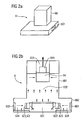
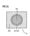
- FIG 2a to 2c show an embodiment of the invention.
- FIG 2a shows a perspective view of the hood with the vortex module 62.
- FIG 2b shows a cross sectional view of the hood, whereas
- FIG 2c shows a bottom view of the hood with the vortex module 62.
- the suction hood 6 comprises a first sucking means 64 which pulls the air to the suction hood by generating an at least substantially direct suction to the suction hood 6 and a second sucking means 62 which pulls the air to the suction hood 6 by generating an at least substantially circular, cyclone or helix movement.
- the suction hood 6 comprises a cuboidal upper part 681 under which a lower part 682 with an at least nearly square shaped upper and lower surface, between which four longish side surfaces are arranged. At the sides of the lower part 682, air inlets 601 and 602 are shown.
- the upper part 681 and the lower part 682 are arranged directly adjacent, where the common surface is left out to allow the air to flow through.
- FIG 2b shows a number of suction channels 623 of the vortex module 62 arranged tangentially around the ring shaped area 622.
- engines blow the air tangentially from the air inlets 601 and 602 through the outer suction area 634 into the inner suction area 631 of the hood 6 and thus generate the circulating air.
- the circulating air in turn, generates a suction which sucks the air into and through the inner suction area 631.
- the air escapes the suction area at the outlet 633. This is also called tornado aspiration.
- a suctions means 64 is arranged centrally in the upper part 681 which is able to suck the air directly upwards through the inner suction area 631 and the outer suction area 634. This is also called standard aspiration.
- the hood 6 can be operated with standard aspiration as well as with Tornado aspiration. This can be done in three different ways:
- the tornado aspiration is added in a pulse working mode, so that the tornado aspiration and standard aspiration are operated alternatively.
- tornado aspiration is used, whereas in the second second, standard aspiration is used.
- tornado aspiration is used again and so on. This means that during the tornado aspiration the suction through the suction area 631 is boosted, while, during the standard aspiration, the suction area is, at least substantially spreaded over the inner suction area 631 and the outer suction area 634.
- the tornado aspiration can be operated in a boost mode to amplify the effect of the standard aspiration. This means that, in a normal mode, only the standard aspiration runs, whereas for boosting, the tornado aspiration is added and boosts the suction mostly in the inner suction area 631.
- the tornado aspiration is operated together with the standard aspiration so that both modes are operated at the same time.
Landscapes
- Engineering & Computer Science (AREA)
- Chemical & Material Sciences (AREA)
- Combustion & Propulsion (AREA)
- Mechanical Engineering (AREA)
- General Engineering & Computer Science (AREA)
- Ventilation (AREA)
- Cyclones (AREA)
- Prevention Of Fouling (AREA)
- Filters For Electric Vacuum Cleaners (AREA)
- Seal Device For Vehicle (AREA)
- Superstructure Of Vehicle (AREA)
Claims (7)
- Abzugshaube, die Luft von einem ersten Bereich in einen zweiten Bereich saugt, und wobei die Haube umfasst:ein erstes Saugmittel (64), das die Luft durch Erzeugung eines zumindest im Wesentlichen direkten Soges zur Abzugshaube zieht, undein zweites Saugmittel (62), das die Luft durch Erzeugung einer zumindest im Wesentlichen kreisförmigen, wirbelnden oder spiralförmigen Bewegung zur Abzugshaube zieht,dadurch gekennzeichnet, dass das zweite Saugmittel (62) in einem Verstärkungsmodus betrieben werden kann, so dass das zweite Saugmittel (62) den Sog des ersten Saugmittels (64) vorübergehend verstärkt,und/oderwobei das erste (64) und das zweite (62) Saugmittel abwechselnd in einem Impulsmodus betrieben werden können.
- Abzugshaube gemäß Anspruch 1, wobei das erste (64) und das zweite (62) Saugmittel auf eine Art zusammen betrieben werden können, dass das zweite Saugmittel (62) den Sog des ersten Saugmittels (64) kontinuierlich verstärkt.
- Abzugshaube gemäß einem der vorangehenden Ansprüche, wobei ein äußerer Saugbereich (634) einen inneren Saugbereich (631) umgibt, wobei vorzugsweisea) das erste Saugmittel (64) die Luft großenteils durch den äußeren Saugbereich (634) zur Abzugshaube saugt, oderb) das zweite Saugmittel (62) die Luft zumindest im Wesentlichen gleichmäßig durch den äußeren Saugbereich (634) und den inneren Saugbereich (631) zur Abzugshaube zieht.
- Abzugshaube gemäß einem der vorangehenden Ansprüche, wobei die Luft zum Betrieb des zweiten Saugmittels (62), bei
dem es sich vorzugsweise um ein Wirbelmodul handelt, seitlich angesaugt wird, und dies vorzugsweisea) durch seitliche Öffnungen (601, 602) und/oderb) vom äußeren Saugbereich (634). - Abzugshaube gemäß einem der vorangehenden Ansprüche,a) wobei dem zweiten Saugmittel (62) ein Zuschaltmittel hinzugefügt werden kann, vorzugsweise in Abhängigkeit von Lärm, Effizienz und/oder Dämpfen,b) wobei das Zuschaltmittel vorzugsweise eine schalter-und/oder sensorbetriebene Vorrichtung ist.
- Abzugshaube gemäß einem der vorangehenden Ansprüche, wobei die Abzugshaubea) eine belüftete Abzugshaube ist, wobei sich der erste Bereich vorzugsweise innerhalb eines Raumes und der zweite Bereich außerhalb des Raumes befindet, und/oderb) eine Umluft-Abzugshaube ist, wobei sich der erste Bereich vorzugsweise innerhalb eines Raumes befindet und auch der zweite Bereich innerhalb des Raumes befindet.
- Verfahren zum Erzeugen eines Luftsoges mittels einer Abzugshaube gemäß einem der vorangehenden Ansprüche.
Priority Applications (25)
| Application Number | Priority Date | Filing Date | Title |
|---|---|---|---|
| EP08021414A EP2196736B1 (de) | 2008-12-10 | 2008-12-10 | Abzugshaube |
| EP12156548.5A EP2487423B1 (de) | 2008-12-10 | 2008-12-10 | Absaughaube |
| AT08021414T ATE549583T1 (de) | 2008-12-10 | 2008-12-10 | Abzugshaube |
| EP09007739.7A EP2196738B1 (de) | 2008-12-10 | 2009-06-12 | Absaughaube |
| CA2746390A CA2746390A1 (en) | 2008-12-10 | 2009-12-10 | Suction hood |
| US13/132,361 US20110232625A1 (en) | 2008-12-10 | 2009-12-10 | Suction hood |
| RU2011128298/03A RU2526932C2 (ru) | 2008-12-10 | 2009-12-10 | Вытяжной колпак |
| BRPI0922445A BRPI0922445B1 (pt) | 2008-12-10 | 2009-12-10 | exaustor de sucção |
| CA2750832A CA2750832A1 (en) | 2008-12-10 | 2009-12-10 | Suction hood |
| JP2011539951A JP5615291B2 (ja) | 2008-12-10 | 2009-12-10 | 吸入フード |
| RU2011128323/03A RU2481529C2 (ru) | 2008-12-10 | 2009-12-10 | Вытяжной колпак |
| MX2011006137A MX2011006137A (es) | 2008-12-10 | 2009-12-10 | Campana de succion. |
| CN200980149221.2A CN102348935B (zh) | 2008-12-10 | 2009-12-10 | 抽吸罩 |
| KR1020117015361A KR20110094110A (ko) | 2008-12-10 | 2009-12-10 | 흡입 후드 |
| JP2011539949A JP2012511684A (ja) | 2008-12-10 | 2009-12-10 | 吸入フード |
| KR1020117015940A KR20110094214A (ko) | 2008-12-10 | 2009-12-10 | 흡입 후드 |
| US13/132,348 US9395090B2 (en) | 2008-12-10 | 2009-12-10 | Suction hood |
| BRPI0922449A BRPI0922449A2 (pt) | 2008-12-10 | 2009-12-10 | coifa de sucção |
| AU2009326529A AU2009326529B2 (en) | 2008-12-10 | 2009-12-10 | Suction hood |
| PCT/EP2009/008823 WO2010066421A2 (en) | 2008-12-10 | 2009-12-10 | Suction hood |
| AU2009326527A AU2009326527A1 (en) | 2008-12-10 | 2009-12-10 | Suction hood |
| CN200980149206.8A CN102282424B (zh) | 2008-12-10 | 2009-12-10 | 抽吸罩 |
| MX2011006053A MX2011006053A (es) | 2008-12-10 | 2009-12-10 | Campana de succion. |
| PCT/EP2009/008825 WO2010066423A2 (en) | 2008-12-10 | 2009-12-10 | Suction hood |
| EP09795698.1A EP2359069B1 (de) | 2008-12-10 | 2009-12-10 | Absaughaube |
Applications Claiming Priority (1)
| Application Number | Priority Date | Filing Date | Title |
|---|---|---|---|
| EP08021414A EP2196736B1 (de) | 2008-12-10 | 2008-12-10 | Abzugshaube |
Related Child Applications (1)
| Application Number | Title | Priority Date | Filing Date |
|---|---|---|---|
| EP12156548.5A Division EP2487423B1 (de) | 2008-12-10 | 2008-12-10 | Absaughaube |
Publications (2)
| Publication Number | Publication Date |
|---|---|
| EP2196736A1 EP2196736A1 (de) | 2010-06-16 |
| EP2196736B1 true EP2196736B1 (de) | 2012-03-14 |
Family
ID=40821681
Family Applications (2)
| Application Number | Title | Priority Date | Filing Date |
|---|---|---|---|
| EP08021414A Not-in-force EP2196736B1 (de) | 2008-12-10 | 2008-12-10 | Abzugshaube |
| EP12156548.5A Not-in-force EP2487423B1 (de) | 2008-12-10 | 2008-12-10 | Absaughaube |
Family Applications After (1)
| Application Number | Title | Priority Date | Filing Date |
|---|---|---|---|
| EP12156548.5A Not-in-force EP2487423B1 (de) | 2008-12-10 | 2008-12-10 | Absaughaube |
Country Status (12)
| Country | Link |
|---|---|
| US (1) | US20110232625A1 (de) |
| EP (2) | EP2196736B1 (de) |
| JP (1) | JP2012511684A (de) |
| KR (1) | KR20110094214A (de) |
| CN (1) | CN102282424B (de) |
| AT (1) | ATE549583T1 (de) |
| AU (1) | AU2009326527A1 (de) |
| BR (1) | BRPI0922449A2 (de) |
| CA (1) | CA2750832A1 (de) |
| MX (1) | MX2011006137A (de) |
| RU (1) | RU2526932C2 (de) |
| WO (1) | WO2010066421A2 (de) |
Families Citing this family (10)
| Publication number | Priority date | Publication date | Assignee | Title |
|---|---|---|---|---|
| CN102954515A (zh) * | 2011-08-27 | 2013-03-06 | 博西华电器(江苏)有限公司 | 龙卷风产生装置和设置有该龙卷风产生装置的抽油烟机 |
| KR101934457B1 (ko) * | 2011-11-17 | 2019-01-04 | 삼성전자주식회사 | 환기 장치와 이를 포함한 환기 시스템 |
| KR102075916B1 (ko) * | 2013-02-21 | 2020-02-11 | 웅진코웨이 주식회사 | 소음 방지 후드 |
| CN105928031B (zh) * | 2014-07-16 | 2017-11-10 | 侯春景 | 一种抽油烟机 |
| CN106091060A (zh) * | 2016-07-26 | 2016-11-09 | 广东万家乐燃气具有限公司 | 一种带有轴流风扇的离心式抽油烟机 |
| WO2018157664A1 (en) * | 2017-02-28 | 2018-09-07 | Lien Fue Sang | Fume cyclonic-collection device, range hood, and kitchen fume-extracting and cooking equipment |
| CN106949520A (zh) * | 2017-05-23 | 2017-07-14 | 成都工业职业技术学院 | 一种旋流式集排油烟机 |
| JP7349597B2 (ja) * | 2019-04-18 | 2023-09-25 | パナソニックIpマネジメント株式会社 | サイクロン分離装置 |
| KR20220044997A (ko) | 2019-08-07 | 2022-04-12 | 에이엔에이치 이노베이션 인크 | 가변 팬 구동부를 지닌 이동식 재순환 그릴 |
| CN111780190A (zh) * | 2020-08-04 | 2020-10-16 | 合肥瑞纳通软件技术开发有限公司 | 一种具有主动导烟装置的抽油烟机 |
Family Cites Families (27)
| Publication number | Priority date | Publication date | Assignee | Title |
|---|---|---|---|---|
| US2793712A (en) * | 1954-02-26 | 1957-05-28 | Dohrmann Hotel Supply Co | Grease extracting attachment for ventilators for kitchen ranges |
| US2889007A (en) * | 1955-12-27 | 1959-06-02 | Dohrmann Hotel Supply Co | Grease extracting ventilator for kitchen ranges |
| DE1274081B (de) * | 1958-08-22 | 1968-08-01 | Siemens Ag | Drehstroemungswirbler zum Trennen von Medien unterschiedlicher Dichte |
| US3664255A (en) * | 1970-07-06 | 1972-05-23 | Irvin R Kuechler | Apparatus and method for removing fumes from the space above a cooking appliance |
| US3800689A (en) * | 1972-07-24 | 1974-04-02 | L Brown | Building ventilating system |
| US4038912A (en) * | 1974-08-15 | 1977-08-02 | Vent-Cair, Inc. | Combination forced-flow and convective-flow grease-hood system and method having a low-level entry portion over a protruding cooking appliance |
| US4506655A (en) * | 1981-02-03 | 1985-03-26 | Kuechler Irvin R | Compact double fan apparatus and method with grease-separating capabilities |
| JPS62261842A (ja) * | 1986-05-09 | 1987-11-14 | Nippon Air Curtain Kk | 人工竜巻発生機構とその利用法 |
| DK312288D0 (da) | 1988-06-08 | 1988-06-08 | Hansen & Raagaard Aps | Fremgangsmaade og anlaeg til mekanisk punktudsugning |
| JPH0264840U (de) * | 1988-11-05 | 1990-05-16 | ||
| JP2538750B2 (ja) * | 1992-11-25 | 1996-10-02 | 鹿島建設株式会社 | 排気装置 |
| FR2736567B1 (fr) * | 1995-07-13 | 1997-08-08 | Europ Equip Menager | Systeme d'aspiration d'emanations, notamment pour hotte aspirante |
| CN2269543Y (zh) * | 1996-06-10 | 1997-12-03 | 彭大齐 | 灯罩式抽油烟机 |
| KR100423116B1 (ko) * | 1998-03-30 | 2004-03-18 | 다이킨 고교 가부시키가이샤 | 흡기·송풍 장치 |
| JP3327247B2 (ja) * | 1999-01-14 | 2002-09-24 | ダイキン工業株式会社 | 換気装置 |
| JP2000234773A (ja) * | 1999-02-15 | 2000-08-29 | Daikin Ind Ltd | 換気装置 |
| JP2001174037A (ja) * | 1999-07-01 | 2001-06-29 | Daikin Ind Ltd | トルネード型吸気・送風装置 |
| US20110005507A9 (en) * | 2001-01-23 | 2011-01-13 | Rick Bagwell | Real-time control of exhaust flow |
| DE10208488A1 (de) * | 2002-02-27 | 2003-09-04 | Bsh Bosch Siemens Hausgeraete | Abzugshaube und Verfahren zur Absaugung und/oder Aufreinigung kontaminierter Trägerstoffe |
| JP3969536B2 (ja) * | 2002-12-27 | 2007-09-05 | 株式会社イトーキ | ヒュームフード |
| JP4526780B2 (ja) * | 2003-04-30 | 2010-08-18 | 富士夫 堀 | フード装置 |
| JP4366236B2 (ja) * | 2004-04-26 | 2009-11-18 | 邦昭 堀越 | 電磁誘導調理器具における換気補助装置 |
| US7699051B2 (en) * | 2005-06-08 | 2010-04-20 | Westen Industries, Inc. | Range hood |
| JP2006349237A (ja) * | 2005-06-15 | 2006-12-28 | Matsushita Electric Ind Co Ltd | レンジフード |
| ITPN20060058A1 (it) * | 2006-07-27 | 2008-01-28 | Electrolux Professional Spa | Cappa di aspirazione a ventilazione perfezionata |
| US20080127403A1 (en) * | 2006-11-30 | 2008-06-05 | Airex, Inc. | Ventilating fan with grill having high static pressure resistance |
| CN201043775Y (zh) * | 2007-03-13 | 2008-04-02 | 杜崇福 | 环保型厨房脱排油烟装置 |
-
2008
- 2008-12-10 AT AT08021414T patent/ATE549583T1/de active
- 2008-12-10 EP EP08021414A patent/EP2196736B1/de not_active Not-in-force
- 2008-12-10 EP EP12156548.5A patent/EP2487423B1/de not_active Not-in-force
-
2009
- 2009-12-10 JP JP2011539949A patent/JP2012511684A/ja not_active Ceased
- 2009-12-10 WO PCT/EP2009/008823 patent/WO2010066421A2/en not_active Ceased
- 2009-12-10 US US13/132,361 patent/US20110232625A1/en not_active Abandoned
- 2009-12-10 CA CA2750832A patent/CA2750832A1/en not_active Abandoned
- 2009-12-10 KR KR1020117015940A patent/KR20110094214A/ko not_active Withdrawn
- 2009-12-10 RU RU2011128298/03A patent/RU2526932C2/ru not_active IP Right Cessation
- 2009-12-10 CN CN200980149206.8A patent/CN102282424B/zh not_active Expired - Fee Related
- 2009-12-10 AU AU2009326527A patent/AU2009326527A1/en not_active Abandoned
- 2009-12-10 BR BRPI0922449A patent/BRPI0922449A2/pt not_active IP Right Cessation
- 2009-12-10 MX MX2011006137A patent/MX2011006137A/es active IP Right Grant
Also Published As
| Publication number | Publication date |
|---|---|
| AU2009326527A1 (en) | 2011-06-23 |
| JP2012511684A (ja) | 2012-05-24 |
| EP2487423B1 (de) | 2014-02-12 |
| EP2487423A1 (de) | 2012-08-15 |
| EP2196736A1 (de) | 2010-06-16 |
| US20110232625A1 (en) | 2011-09-29 |
| RU2011128298A (ru) | 2013-01-20 |
| CA2750832A1 (en) | 2010-06-17 |
| WO2010066421A3 (en) | 2011-08-11 |
| WO2010066421A2 (en) | 2010-06-17 |
| CN102282424A (zh) | 2011-12-14 |
| ATE549583T1 (de) | 2012-03-15 |
| KR20110094214A (ko) | 2011-08-22 |
| CN102282424B (zh) | 2014-08-20 |
| RU2526932C2 (ru) | 2014-08-27 |
| BRPI0922449A2 (pt) | 2018-11-06 |
| MX2011006137A (es) | 2011-07-28 |
Similar Documents
| Publication | Publication Date | Title |
|---|---|---|
| EP2487423B1 (de) | Absaughaube | |
| EP2359068B1 (de) | Absaughaube | |
| EP2196738B1 (de) | Absaughaube | |
| US10900665B2 (en) | Combination appliance having a cooktop and steam extraction device | |
| CA2429580A1 (en) | Vent hood for a kitchen stove | |
| WO2019120854A1 (en) | Exhaust hood with forced air injection | |
| HK1162067A (en) | Suction hood | |
| HK1161343A (en) | Suction hood | |
| HK1164424A (zh) | 抽吸罩 |
Legal Events
| Date | Code | Title | Description |
|---|---|---|---|
| PUAI | Public reference made under article 153(3) epc to a published international application that has entered the european phase |
Free format text: ORIGINAL CODE: 0009012 |
|
| AK | Designated contracting states |
Kind code of ref document: A1 Designated state(s): AT BE BG CH CY CZ DE DK EE ES FI FR GB GR HR HU IE IS IT LI LT LU LV MC MT NL NO PL PT RO SE SI SK TR |
|
| AX | Request for extension of the european patent |
Extension state: AL BA MK RS |
|
| 17P | Request for examination filed |
Effective date: 20100608 |
|
| 17Q | First examination report despatched |
Effective date: 20100715 |
|
| AKX | Designation fees paid |
Designated state(s): AT BE BG CH CY CZ DE DK EE ES FI FR GB GR HR HU IE IS IT LI LT LU LV MC MT NL NO PL PT RO SE SI SK TR |
|
| RAP1 | Party data changed (applicant data changed or rights of an application transferred) |
Owner name: ELECTROLUX HOME PRODUCTS CORPORATION N.V. |
|
| RAP1 | Party data changed (applicant data changed or rights of an application transferred) |
Owner name: ELECTROLUX HOME PRODUCTS CORPORATION N.V. |
|
| GRAP | Despatch of communication of intention to grant a patent |
Free format text: ORIGINAL CODE: EPIDOSNIGR1 |
|
| GRAS | Grant fee paid |
Free format text: ORIGINAL CODE: EPIDOSNIGR3 |
|
| GRAA | (expected) grant |
Free format text: ORIGINAL CODE: 0009210 |
|
| AK | Designated contracting states |
Kind code of ref document: B1 Designated state(s): AT BE BG CH CY CZ DE DK EE ES FI FR GB GR HR HU IE IS IT LI LT LU LV MC MT NL NO PL PT RO SE SI SK TR |
|
| REG | Reference to a national code |
Ref country code: GB Ref legal event code: FG4D |
|
| REG | Reference to a national code |
Ref country code: AT Ref legal event code: REF Ref document number: 549583 Country of ref document: AT Kind code of ref document: T Effective date: 20120315 Ref country code: CH Ref legal event code: EP |
|
| REG | Reference to a national code |
Ref country code: IE Ref legal event code: FG4D |
|
| REG | Reference to a national code |
Ref country code: DE Ref legal event code: R096 Ref document number: 602008014052 Country of ref document: DE Effective date: 20120510 |
|
| REG | Reference to a national code |
Ref country code: SE Ref legal event code: TRGR |
|
| REG | Reference to a national code |
Ref country code: NL Ref legal event code: VDEP Effective date: 20120314 |
|
| PG25 | Lapsed in a contracting state [announced via postgrant information from national office to epo] |
Ref country code: NO Free format text: LAPSE BECAUSE OF FAILURE TO SUBMIT A TRANSLATION OF THE DESCRIPTION OR TO PAY THE FEE WITHIN THE PRESCRIBED TIME-LIMIT Effective date: 20120614 Ref country code: HR Free format text: LAPSE BECAUSE OF FAILURE TO SUBMIT A TRANSLATION OF THE DESCRIPTION OR TO PAY THE FEE WITHIN THE PRESCRIBED TIME-LIMIT Effective date: 20120314 Ref country code: LT Free format text: LAPSE BECAUSE OF FAILURE TO SUBMIT A TRANSLATION OF THE DESCRIPTION OR TO PAY THE FEE WITHIN THE PRESCRIBED TIME-LIMIT Effective date: 20120314 |
|
| LTIE | Lt: invalidation of european patent or patent extension |
Effective date: 20120314 |
|
| PG25 | Lapsed in a contracting state [announced via postgrant information from national office to epo] |
Ref country code: FI Free format text: LAPSE BECAUSE OF FAILURE TO SUBMIT A TRANSLATION OF THE DESCRIPTION OR TO PAY THE FEE WITHIN THE PRESCRIBED TIME-LIMIT Effective date: 20120314 Ref country code: GR Free format text: LAPSE BECAUSE OF FAILURE TO SUBMIT A TRANSLATION OF THE DESCRIPTION OR TO PAY THE FEE WITHIN THE PRESCRIBED TIME-LIMIT Effective date: 20120615 Ref country code: LV Free format text: LAPSE BECAUSE OF FAILURE TO SUBMIT A TRANSLATION OF THE DESCRIPTION OR TO PAY THE FEE WITHIN THE PRESCRIBED TIME-LIMIT Effective date: 20120314 |
|
| REG | Reference to a national code |
Ref country code: AT Ref legal event code: MK05 Ref document number: 549583 Country of ref document: AT Kind code of ref document: T Effective date: 20120314 |
|
| PG25 | Lapsed in a contracting state [announced via postgrant information from national office to epo] |
Ref country code: CY Free format text: LAPSE BECAUSE OF FAILURE TO SUBMIT A TRANSLATION OF THE DESCRIPTION OR TO PAY THE FEE WITHIN THE PRESCRIBED TIME-LIMIT Effective date: 20120314 |
|
| PG25 | Lapsed in a contracting state [announced via postgrant information from national office to epo] |
Ref country code: EE Free format text: LAPSE BECAUSE OF FAILURE TO SUBMIT A TRANSLATION OF THE DESCRIPTION OR TO PAY THE FEE WITHIN THE PRESCRIBED TIME-LIMIT Effective date: 20120314 Ref country code: SI Free format text: LAPSE BECAUSE OF FAILURE TO SUBMIT A TRANSLATION OF THE DESCRIPTION OR TO PAY THE FEE WITHIN THE PRESCRIBED TIME-LIMIT Effective date: 20120314 Ref country code: BE Free format text: LAPSE BECAUSE OF FAILURE TO SUBMIT A TRANSLATION OF THE DESCRIPTION OR TO PAY THE FEE WITHIN THE PRESCRIBED TIME-LIMIT Effective date: 20120314 Ref country code: RO Free format text: LAPSE BECAUSE OF FAILURE TO SUBMIT A TRANSLATION OF THE DESCRIPTION OR TO PAY THE FEE WITHIN THE PRESCRIBED TIME-LIMIT Effective date: 20120314 Ref country code: CZ Free format text: LAPSE BECAUSE OF FAILURE TO SUBMIT A TRANSLATION OF THE DESCRIPTION OR TO PAY THE FEE WITHIN THE PRESCRIBED TIME-LIMIT Effective date: 20120314 Ref country code: IS Free format text: LAPSE BECAUSE OF FAILURE TO SUBMIT A TRANSLATION OF THE DESCRIPTION OR TO PAY THE FEE WITHIN THE PRESCRIBED TIME-LIMIT Effective date: 20120714 Ref country code: PL Free format text: LAPSE BECAUSE OF FAILURE TO SUBMIT A TRANSLATION OF THE DESCRIPTION OR TO PAY THE FEE WITHIN THE PRESCRIBED TIME-LIMIT Effective date: 20120314 |
|
| PG25 | Lapsed in a contracting state [announced via postgrant information from national office to epo] |
Ref country code: SK Free format text: LAPSE BECAUSE OF FAILURE TO SUBMIT A TRANSLATION OF THE DESCRIPTION OR TO PAY THE FEE WITHIN THE PRESCRIBED TIME-LIMIT Effective date: 20120314 Ref country code: PT Free format text: LAPSE BECAUSE OF FAILURE TO SUBMIT A TRANSLATION OF THE DESCRIPTION OR TO PAY THE FEE WITHIN THE PRESCRIBED TIME-LIMIT Effective date: 20120716 |
|
| PLBE | No opposition filed within time limit |
Free format text: ORIGINAL CODE: 0009261 |
|
| STAA | Information on the status of an ep patent application or granted ep patent |
Free format text: STATUS: NO OPPOSITION FILED WITHIN TIME LIMIT |
|
| PG25 | Lapsed in a contracting state [announced via postgrant information from national office to epo] |
Ref country code: AT Free format text: LAPSE BECAUSE OF FAILURE TO SUBMIT A TRANSLATION OF THE DESCRIPTION OR TO PAY THE FEE WITHIN THE PRESCRIBED TIME-LIMIT Effective date: 20120314 Ref country code: NL Free format text: LAPSE BECAUSE OF FAILURE TO SUBMIT A TRANSLATION OF THE DESCRIPTION OR TO PAY THE FEE WITHIN THE PRESCRIBED TIME-LIMIT Effective date: 20120314 Ref country code: DK Free format text: LAPSE BECAUSE OF FAILURE TO SUBMIT A TRANSLATION OF THE DESCRIPTION OR TO PAY THE FEE WITHIN THE PRESCRIBED TIME-LIMIT Effective date: 20120314 |
|
| 26N | No opposition filed |
Effective date: 20121217 |
|
| REG | Reference to a national code |
Ref country code: DE Ref legal event code: R097 Ref document number: 602008014052 Country of ref document: DE Effective date: 20121217 |
|
| PG25 | Lapsed in a contracting state [announced via postgrant information from national office to epo] |
Ref country code: ES Free format text: LAPSE BECAUSE OF FAILURE TO SUBMIT A TRANSLATION OF THE DESCRIPTION OR TO PAY THE FEE WITHIN THE PRESCRIBED TIME-LIMIT Effective date: 20120625 |
|
| PG25 | Lapsed in a contracting state [announced via postgrant information from national office to epo] |
Ref country code: SE Free format text: LAPSE BECAUSE OF NON-PAYMENT OF DUE FEES Effective date: 20121211 Ref country code: MC Free format text: LAPSE BECAUSE OF NON-PAYMENT OF DUE FEES Effective date: 20121231 Ref country code: BG Free format text: LAPSE BECAUSE OF FAILURE TO SUBMIT A TRANSLATION OF THE DESCRIPTION OR TO PAY THE FEE WITHIN THE PRESCRIBED TIME-LIMIT Effective date: 20120614 |
|
| REG | Reference to a national code |
Ref country code: CH Ref legal event code: PL |
|
| REG | Reference to a national code |
Ref country code: IE Ref legal event code: MM4A |
|
| PG25 | Lapsed in a contracting state [announced via postgrant information from national office to epo] |
Ref country code: IE Free format text: LAPSE BECAUSE OF NON-PAYMENT OF DUE FEES Effective date: 20121210 Ref country code: LI Free format text: LAPSE BECAUSE OF NON-PAYMENT OF DUE FEES Effective date: 20121231 Ref country code: CH Free format text: LAPSE BECAUSE OF NON-PAYMENT OF DUE FEES Effective date: 20121231 |
|
| PG25 | Lapsed in a contracting state [announced via postgrant information from national office to epo] |
Ref country code: MT Free format text: LAPSE BECAUSE OF FAILURE TO SUBMIT A TRANSLATION OF THE DESCRIPTION OR TO PAY THE FEE WITHIN THE PRESCRIBED TIME-LIMIT Effective date: 20120314 |
|
| PG25 | Lapsed in a contracting state [announced via postgrant information from national office to epo] |
Ref country code: TR Free format text: LAPSE BECAUSE OF FAILURE TO SUBMIT A TRANSLATION OF THE DESCRIPTION OR TO PAY THE FEE WITHIN THE PRESCRIBED TIME-LIMIT Effective date: 20120314 |
|
| PG25 | Lapsed in a contracting state [announced via postgrant information from national office to epo] |
Ref country code: LU Free format text: LAPSE BECAUSE OF NON-PAYMENT OF DUE FEES Effective date: 20121210 |
|
| PG25 | Lapsed in a contracting state [announced via postgrant information from national office to epo] |
Ref country code: HU Free format text: LAPSE BECAUSE OF FAILURE TO SUBMIT A TRANSLATION OF THE DESCRIPTION OR TO PAY THE FEE WITHIN THE PRESCRIBED TIME-LIMIT Effective date: 20081210 |
|
| REG | Reference to a national code |
Ref country code: FR Ref legal event code: PLFP Year of fee payment: 8 |
|
| REG | Reference to a national code |
Ref country code: FR Ref legal event code: PLFP Year of fee payment: 9 |
|
| REG | Reference to a national code |
Ref country code: FR Ref legal event code: PLFP Year of fee payment: 10 |
|
| PGFP | Annual fee paid to national office [announced via postgrant information from national office to epo] |
Ref country code: DE Payment date: 20191210 Year of fee payment: 12 |
|
| PGFP | Annual fee paid to national office [announced via postgrant information from national office to epo] |
Ref country code: FR Payment date: 20191220 Year of fee payment: 12 Ref country code: IT Payment date: 20191230 Year of fee payment: 12 |
|
| PGFP | Annual fee paid to national office [announced via postgrant information from national office to epo] |
Ref country code: GB Payment date: 20191220 Year of fee payment: 12 |
|
| REG | Reference to a national code |
Ref country code: DE Ref legal event code: R119 Ref document number: 602008014052 Country of ref document: DE |
|
| GBPC | Gb: european patent ceased through non-payment of renewal fee |
Effective date: 20201210 |
|
| PG25 | Lapsed in a contracting state [announced via postgrant information from national office to epo] |
Ref country code: IT Free format text: LAPSE BECAUSE OF NON-PAYMENT OF DUE FEES Effective date: 20201210 Ref country code: FR Free format text: LAPSE BECAUSE OF NON-PAYMENT OF DUE FEES Effective date: 20201231 |
|
| PG25 | Lapsed in a contracting state [announced via postgrant information from national office to epo] |
Ref country code: DE Free format text: LAPSE BECAUSE OF NON-PAYMENT OF DUE FEES Effective date: 20210701 Ref country code: GB Free format text: LAPSE BECAUSE OF NON-PAYMENT OF DUE FEES Effective date: 20201210 |