EP2196758A1 - Echangeur de chaleur - Google Patents
Echangeur de chaleur Download PDFInfo
- Publication number
- EP2196758A1 EP2196758A1 EP08792643A EP08792643A EP2196758A1 EP 2196758 A1 EP2196758 A1 EP 2196758A1 EP 08792643 A EP08792643 A EP 08792643A EP 08792643 A EP08792643 A EP 08792643A EP 2196758 A1 EP2196758 A1 EP 2196758A1
- Authority
- EP
- European Patent Office
- Prior art keywords
- corrugated fins
- downwind
- upwind
- flat tubes
- gap
- Prior art date
- Legal status (The legal status is an assumption and is not a legal conclusion. Google has not performed a legal analysis and makes no representation as to the accuracy of the status listed.)
- Granted
Links
- XLYOFNOQVPJJNP-UHFFFAOYSA-N water Substances O XLYOFNOQVPJJNP-UHFFFAOYSA-N 0.000 claims abstract description 47
- 239000003507 refrigerant Substances 0.000 claims abstract description 10
- 239000003570 air Substances 0.000 description 29
- 238000002474 experimental method Methods 0.000 description 9
- 238000010257 thawing Methods 0.000 description 6
- 239000011295 pitch Substances 0.000 description 5
- 230000017525 heat dissipation Effects 0.000 description 4
- 230000001965 increasing effect Effects 0.000 description 4
- 238000000034 method Methods 0.000 description 4
- 230000000717 retained effect Effects 0.000 description 4
- 229910052782 aluminium Inorganic materials 0.000 description 3
- XAGFODPZIPBFFR-UHFFFAOYSA-N aluminium Chemical compound [Al] XAGFODPZIPBFFR-UHFFFAOYSA-N 0.000 description 3
- 239000000463 material Substances 0.000 description 3
- 238000005259 measurement Methods 0.000 description 3
- 238000002844 melting Methods 0.000 description 3
- 230000008018 melting Effects 0.000 description 3
- 238000003466 welding Methods 0.000 description 3
- 230000000694 effects Effects 0.000 description 2
- 238000010521 absorption reaction Methods 0.000 description 1
- 239000012080 ambient air Substances 0.000 description 1
- 230000002708 enhancing effect Effects 0.000 description 1
- 238000010438 heat treatment Methods 0.000 description 1
- 229910052751 metal Inorganic materials 0.000 description 1
- 239000002184 metal Substances 0.000 description 1
- 238000012986 modification Methods 0.000 description 1
- 230000004048 modification Effects 0.000 description 1
Images








Classifications
-
- F—MECHANICAL ENGINEERING; LIGHTING; HEATING; WEAPONS; BLASTING
- F28—HEAT EXCHANGE IN GENERAL
- F28F—DETAILS OF HEAT-EXCHANGE AND HEAT-TRANSFER APPARATUS, OF GENERAL APPLICATION
- F28F1/00—Tubular elements; Assemblies of tubular elements
- F28F1/10—Tubular elements and assemblies thereof with means for increasing heat-transfer area, e.g. with fins, with projections, with recesses
- F28F1/12—Tubular elements and assemblies thereof with means for increasing heat-transfer area, e.g. with fins, with projections, with recesses the means being only outside the tubular element
- F28F1/126—Tubular elements and assemblies thereof with means for increasing heat-transfer area, e.g. with fins, with projections, with recesses the means being only outside the tubular element consisting of zig-zag shaped fins
-
- F—MECHANICAL ENGINEERING; LIGHTING; HEATING; WEAPONS; BLASTING
- F28—HEAT EXCHANGE IN GENERAL
- F28F—DETAILS OF HEAT-EXCHANGE AND HEAT-TRANSFER APPARATUS, OF GENERAL APPLICATION
- F28F17/00—Removing ice or water from heat-exchange apparatus
- F28F17/005—Means for draining condensates from heat exchangers, e.g. from evaporators
Definitions
- the present invention relates to a parallel-flow-type heat exchanger.
- a parallel-flow-type heat exchanger having a plurality of flat tubes arranged between a plurality of header pipes, with refrigerant passages inside the flat tubes communicating with the insides of the header pipes, and with corrugated fins arranged between the flat tubes, is widely used in car air conditioners and the like.
- An example is seen in Patent Document 1.
- the heat exchanger described in Patent Document 1 has a plurality of header pipes arranged horizontally, and has a plurality of flat tubes arranged vertically, and corrugated fins between the flat tubes are shaped like valleys with their bottom at a central part of the heat exchanger in the depth direction. At the valley-bottom part of the corrugated fins, where they join the flat tubes, through holes are formed; when defrosting operation is performed to melt frost sticking to the heat exchanger, the water resulting from the frost melting is drained through the through holes.
- Patent Document 1 JP-A-2005-24187
- the corrugated fins are not flat but so shaped as to form valley bottoms, that is, V-shaped to have a downward slope and an upward slope, is effective in increasing the heat-dissipation area and enhancing the heat exchange efficiency.
- V-shaped to have a downward slope and an upward slope is effective in increasing the heat-dissipation area and enhancing the heat exchange efficiency.
- the problem of how to deal with the condensed water or frost that forms when the heat exchanger is used as an evaporator remains.
- the bridging phenomenon also occurs between the corrugations of the corrugated fins, often causing a situation in which water that has flowed down to the ends of the corrugated fins simply forms a film and does not drip down. This is true not only with defrost water but also with condensed water before forming frost.
- the diameter of the through holes are increased, the contact area between the flat tubes and the corrugated fins is reduced, lowering the heat exchange performance; if the ridge-valley pitch of the corrugated fin is increased, the heat-dissipation area of the corrugated fin is reduced, likewise lowering the heat exchange performance.
- the present invention is devised in view of the foregoing, and its obj ect is to provide a parallel-flow-type heat exchanger in which the shape of corrugated fins is so improved as to enhance heat exchange performance and that allows smooth draining of defrost water and condensed water.
- a heat exchanger comprises: horizontal header pipes arranged parallel at an interval from one another in the vertical direction; a plurality of vertical flat tubes arranged at an interval from one another in the horizontal direction between the header pipes, with refrigerant passages inside the flat tubes communicating with the insides of the header pipes respectively; and corrugated fins arranged between the flat tubes.
- the corrugated fins comprise upwind-side corrugated fins whose fin surface has a downward slope toward the downwind side and downwind-side corrugated fins whose fin surface has an upward slope toward the downwind side.
- the downwind-side ends of the upwind-side corrugated fins and the upwind-side ends of the downwind-side corrugated fins are arranged with a gap secured therebetween, and the gap is so sized as to enable water droplets sticking to the downwind-side ends of the upwind-side corrugated fins and water droplets sticking to the upwind-side ends of the downwind-side corrugated fins to coalesce.
- the corrugated fins as a whole extend long in the air flow direction, resulting in an increased heat-dissipation area and enhanced heat exchange performance.
- the upwind-side corrugated fins and the downwind-side corrugated fins are not in close contact with each other, but the downwind-side ends of the upwind-side corrugated fins and the upwind-side ends of the downwind-side corrugated fins are arranged with a gap secured therebetween that is so sized as to enable water droplets sticking to the downwind-side ends of the upwind-side corrugated fins and water droplets sticking to the upwind-side ends to the downwind-side corrugated fins to coalesce.
- the downwind-side ends of the upwind-side corrugated fins and the upwind-side ends of the downwind-side corrugated fins may be kept in partial contact with each other so that the gap is produced elsewhere than in a contact part.
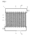
- a heat exchanger 1 has two horizontal header pipes 2 and 3 arranged parallel at an interval from each other in the vertical direction, and has a plurality of vertical flat tubes 4 arranged at an interval from each other and with a predetermined pitch in the horizontal direction between the header pipes 2 and 3, with refrigerant passages 5 inside the flat tubes 4 communicating with insides of the header pipes 2 and 3.
- the header pipes 2 and 3 and the flat tubes 4 are fixed by welding.
- corrugated fins 6 are arranged.
- the flat tubes 4 and the corrugated fins 6 also are fixed by welding.
- the header pipes 2 and 3, the flat tubes 4, and the corrugated fins 6 are all formed of a metal (for example, aluminum) with high thermal conductivity.
- the top side of the page is the top side in the vertical direction
- the bottom side of the page is the bottom side in the vertical direction.
- a plurality of flat tubes 4 are arranged with a predetermined pitch with their length direction kept vertical.
- the heat-dissipation (heat-absorption) area of the heat exchanger 1 is large, allowing efficient heat exchange.
- a refrigerant inflow port 7 is provided, and, at one end of the top-side header pipe 2, a refrigerant outflow port 8 is provided at a position diagonal to the refrigerant inflow port 7.
- the left side of the page is the upwind side
- the right side of the page is the downwind side
- the near-left side of the page is the upwind side
- the far-right side of the page is the downwind side.
- the left side of the page is the upwind side
- the right side of the page is the downwind side; in a perspective view like Fig.
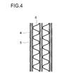
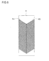
- the corrugated fins 6 divide into upwind-side corrugated fins 6U and downwind-side corrugated fins 6D, and are individually welded to the flat tubes 4.
- the upwind-side corrugated fins 6U have a fin surface with a downward slope toward the downwind side; the downwind-side corrugated fins 6D have a fin surface with an upward slope toward the downwind side.
- the downward slope of the upwind-side corrugated fins 6U and the upward slope of the downwind-side corrugated fins has the same angle.
- the horizontal direction length of the upwind-side corrugated fins 6U and the horizontal direction length of the downwind-side corrugated fins 6D are equal.
- the upwind-side corrugated fins 6U and the downwind-side corrugated fins 6D appear to be a large number of V shapes arranged in the up/down direction.
- the V shapes here, however, are not closed but open at their bottom part.
- the upwind-side corrugated fins 6U and the downwind-side corrugated fins 6D are not in close contact with each other, but are arranged with a gap 9 secured between them.
- the gap 9 is so sized as to enable water droplets sticking to the downwind-side ends of the upwind-side corrugated fins 6U and water droplets sticking to the upwind-side ends downwind-side corrugated fins 6D to coalesce.
- the heat exchanger 1 When refrigerant is passed through the heat exchanger 1 while air is circulated with an unillustrated fan, in an operation mode in which the heat exchanger 1 is used as an evaporator (for example, when heating operation is performed by use of the heat exchanger 1 in the outdoor unit of a separate-type air conditioner comprising an indoor unit and an outdoor unit, the heat exchanger 1 acts as an evaporator), the heat exchanger 1 absorbs heat from the air, and in return releases cold into the air.
- the upwind-side corrugated fins 6U and the downwind-side corrugated fins 6D each have a sloped fin surface, compared with in a case where corrugated fins have no slope and are arranged horizontally, the corrugated fins 6 as a whole extend longer in the air flow direction, achieving high heat exchange performance.
- the gap 9 is so sized as to enable water droplets sticking to the downwind-side ends of the upwind-side corrugated fins 6U and water droplets sticking to the upwind-side ends of the downwind-side corrugated fins 6D to coalesce, when water droplets on the upwind-side corrugated fins 6U and water droplets on the downwind-side corrugated fins 6D meet at the gap 9, they break each other's surface tension and coalesce, and flow out through the gap 9 without causing a bridging phenomenon.
- an operation mode in which the heat exchanger 1 is used as an evaporator (an operation mode in which the heat exchanger 1 absorbs heat from the air)
- moisture in the air may, in the form of frost, stick to the surface of the flat tubes 4 and the corrugated fins 6.
- frost gets thicker and lowers heat exchange performance; thus it is necessary to perform, from time to time, defrosting operation to melt frost.
- Trickles of defrost water resulting from frost melting also, when they meet at the gap 9, break each other's surface tension and coalesce, and flow out through the gap 9 without causing a bridging phenomenon.
- the downward slope of the upwind-side corrugated fins 6U and the upward slope of the downwind-side corrugated fins 6D can be selected within the range of 5° to 40°. The sharper the slope, the larger the heat exchange area and thus the easier it is to drain, but the higher the resistance to the circulation of air. It is therefore advisable to set the angle at an appropriate value through experiments.
- the interval between the flat tubes 4 is 5.5 mm; the thickness of the flat tubes 4 is 1.3 mm; in the air flow direction, the horizontal direction length of both the upwind-side corrugated fins 6U and the downwind-side corrugated fins 6D is 18 mm; the ridge-valley pitch of both the upwind-side corrugated fins 6U and the downwind-side corrugated fins 6D is 2 mm to 3 mm; the size of the gap 9 is 0.5 mm at the maximum. Needless to say, these values are merely examples, and are not meant to limit the contents of the invention.
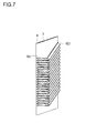
- a second embodiment of the present invention is shown in Figs. 7 and 8 .
- the second embodiment differs from the first embodiment in the angles of the slopes of the upwind-side corrugated fins 6U and the downwind-side corrugated fins 6D.
- the downward slope of the upwind-side corrugated fins 6U is gentler than in the first embodiment, and by contrast the upward slope of the downwind-side corrugated fins 6D is sharper than in the first embodiment.
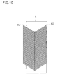
- a third embodiment of the present invention is shown in Figs. 9 and 10 .
- the third embodiment differs from the first embodiment in that the gap 9 between the upwind-side corrugated fins 6U and the downwind-side corrugated fins 6D is arranged displaced to the upwind side from the center of the width of the flat tubes 4 in the air flow direction.
- the arrangement is such that the upwind-side ends of the upwind-side corrugated fins 6U extend off the upwind-side ends of the flat tubes 4 and that the downwind-side ends of the downwind-side corrugated fins are flush with the downwind-side ends of the flat tubes 4.
- the arrangement is such that the sum of the horizontal-direction lengths of the upwind-side corrugated fins 6U and the downwind-side corrugated fins 6D in the air flow direction and the horizontal-direction width of the gap 9 (hereinafter this sum will also be referred to as the corrugated fin horizontal-direction length) is greater than the width of the flat tubes 4 in the air flow direction, and that the downwind-side ends of the downwind-side corrugated fins 6D are flush with the downwind-side ends of the flat tubes 4.
- the horizontal-direction length of the upwind-side corrugated fins 6U and the downwind-side corrugated fins 6D in the air flow direction are both 18 mm, and that the horizontal-direction width of the gap 9 is 0.5 mm. Then the corrugated fin horizontal-direction length is 36.5 mm.
- the gap 9 is arranged about 3 mm to 3.5 mm displaced to the upwind side from the center of the flat tubes 4, and the upwind-side ends of the upwind-side corrugated fins 6U extend 6.5 mm off the upwind-side ends of the flat tubes 4.
- the horizontal-direction lengths of the upwind-side corrugated fins 6U and the downwind-side corrugated fins in the air flow direction do not necessarily have to be equal, but may be different.
- a fourth embodiment of the present invention is shown in Figs. 11 and 12 .
- the fourth embodiment differs from the first embodiment in the length of the upwind-side corrugated fins 6U and the downwind-side corrugated fins 6D.
- the horizontal-direction lengths of the upwind-side corrugated fins and the downwind-side corrugated fins 6D in the air flow direction are greater than in the first embodiment, with the upwind-side ends of the upwind-side corrugated fins 6U extending off upwind-side ends of the flat tubes 4, and with the downwind-side ends of the downwind-side corrugated fins 6D extending off the downwind-side ends of the flat tubes 4.
- a fifth embodiment of the present invention is shown in Figs. 13 and 14 .
- the fifth embodiment differs from the first embodiment in the ratio between the lengths of the upwind-side corrugated fins 6U and the downwind-side corrugated fins 6D.
- the horizontal-direction lengths of the upwind-side corrugated fins 6U and the downwind-side corrugated fins 6D in the air flow direction are equal
- the downwind-side corrugated fins 6D are longer than the upwind-side corrugated fins 6U.
- a sixth embodiment of the present invention is shown in Fig. 15 .
- the sixth embodiment differs from the first embodiment in the structure of the flat tubes 4. Specifically, whereas in the first embodiment the upwind-side corrugated fins 6U and the downwind-side corrugated fins 6D are welded to single flat tubes 4, in the sixth embodiment the flat tubes separate into upwind-side flat tubes 4U and downwind-side flat tubes 4D, with the upwind-side corrugated fins 6U welded to the upwind-side flat tubes 4U, and with the downwind-side corrugated fins 6D welded to the downwind-side flat tubes 4D.
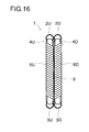
- a seventh embodiment of the present invention is shown in Fig. 16 .
- the seventh embodiment is an advancement one step forward from the sixth embodiment.
- the header pipes separate into upwind-side header pipes 2U and 3U and downwind-side header pipes 2D and 3D.
- the gap 9 is the distance between the downwind-side ends of the upwind-side corrugated fins 6U and the upwind-side ends of the downwind-side corrugated fins 6D, and therefore not only the distance in the horizontal direction but also the distance in the vertical direction is an element of the gap 9.
- the downwind-side ends of the upwind-side corrugated fins 6U and the upwind-side ends of the downwind-side corrugated fins 6D have an equal height, only the horizontal-direction distance between the opposite ends determines the size of the gap 9.
- the gap 9 is formed by setting, with an unillustrated fixture, the relative positions of the upwind-side corrugated fins 6U and the downwind-side corrugated fins 6D and then welding them to the flat tubes. Instead any other method may be adopted. One such method is to bring the downwind-side ends of the upwind-side corrugated fins 6U and the upwind-side ends of the downwind-side corrugated fins 6D into partial contact with each other so that, elsewhere than in their contact part, the gap 9 is formed.
- the method proceeds as follows. Like the upwind-side corrugated fins 6U and the downwind-side corrugated fins 6D shown in Fig. 5 , on an elongate aluminum material (for example, a thin rectangular plate-shaped elongate aluminum material), corrugations, that is, ridge-like, shapes are formed obliquely to the length direction of the material.
- the corrugated fins thus produced have ends that are not straight, and therefore when two of them are put together, they make contact with each other in some part (contact part) but do not make contact with each other in the other part (non-contact part).
- the non-contact part serves as the gap 9. With consideration given so that the contact part does not unduly hinder the outflow of water, the ratio between the contact part and the non-contact part is determined.
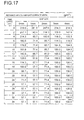
- the results of experiments conducted to study the effect of the size of the gap 9 on drainage is shown in a table in Fig. 17 and in a graph in Fig. 18 .
- the heat exchanger 1 that had been dipped in water was lifted out of water, and its mass was measured; the difference between the measured value and the dry weight of the heat exchanger 1 was taken as the retained water amount. Measurements were made every two seconds starting at the moment of lifting-out (with the lapse of time zero).
- the unit of the retained water amount in the table is the mass of the water retained in the heat exchanger assuming that its surface area is 1 m 2 (the actual surface area of the heat exchanger was converted in this way).
- the dimensional specifications of the heat exchanger used in the above experiments are as follows: the thickness of the flat tubes is 1.3 mm; the size of the gap between the flat tubes is 3.5 mm; the horizontal width of the flat tubes in the air flow direction is 23 mm; the horizontal width of the upwind-side corrugated fins in the air flow direction and the horizontal width of the downwind-side corrugated fins in the air flow direction are both 18 mm; the vertical-direction length of the upwind-side corrugated fins and the downwind-side corrugated fins are both 160 mm; the ridge-valley pitches of the upwind-side corrugated fins and the downwind-side corrugated fins are both 1.7 mm; the wall thicknesses of the upwind-side corrugated fins and the downwind-side corrugated fins are both 0.1 mm; and the slopes of the upwind-side corrugated fins and the downwind-side corrugated fins are both 32°.
- the state in which the upwind-side corrugated fins and the downwind-side corrugated fins are put together is assumed to be one in which "the size of the gap is 0 mm", and measurements are made while the upwind-side corrugated fins and the downwind-side corrugated fins are increasingly taken apart from each other in steps of 1 mm from that state.
- the statement "the size of the gap is 0 mm” holds true only in the contact part, and elsewhere there is a gap. That is, the statement “the size of the gap is 0 mm” does not mean that there is no drain passage between the upwind-side corrugated fins and the downwind-side corrugated fins.
- the gap be 3 mm or less.
- the gap be 2 mm or less; with consideration given also to the speed of drainage, it is preferable that the gap be about 1 mm.
- the present invention finds wide application in parallel-flow-type heat exchangers.
Landscapes
- Physics & Mathematics (AREA)
- Engineering & Computer Science (AREA)
- Geometry (AREA)
- Thermal Sciences (AREA)
- Mechanical Engineering (AREA)
- General Engineering & Computer Science (AREA)
- Heat-Exchange Devices With Radiators And Conduit Assemblies (AREA)
Applications Claiming Priority (2)
| Application Number | Priority Date | Filing Date | Title |
|---|---|---|---|
| JP2007261103A JP4334588B2 (ja) | 2007-10-04 | 2007-10-04 | 熱交換器 |
| PCT/JP2008/064972 WO2009044593A1 (fr) | 2007-10-04 | 2008-08-22 | Echangeur de chaleur |
Publications (3)
| Publication Number | Publication Date |
|---|---|
| EP2196758A1 true EP2196758A1 (fr) | 2010-06-16 |
| EP2196758A4 EP2196758A4 (fr) | 2014-01-15 |
| EP2196758B1 EP2196758B1 (fr) | 2017-11-22 |
Family
ID=40526022
Family Applications (1)
| Application Number | Title | Priority Date | Filing Date |
|---|---|---|---|
| EP08792643.2A Not-in-force EP2196758B1 (fr) | 2007-10-04 | 2008-08-22 | Echangeur de chaleur |
Country Status (4)
| Country | Link |
|---|---|
| EP (1) | EP2196758B1 (fr) |
| JP (1) | JP4334588B2 (fr) |
| CN (1) | CN101802539B (fr) |
| WO (1) | WO2009044593A1 (fr) |
Cited By (3)
| Publication number | Priority date | Publication date | Assignee | Title |
|---|---|---|---|---|
| CN102012134A (zh) * | 2010-10-19 | 2011-04-13 | 广东美的制冷设备有限公司 | 一种利于排水的换热器 |
| US20130240187A1 (en) * | 2010-12-22 | 2013-09-19 | Sharp Kabushiki Kaisha | Heat exchanger and air conditioner equipped with same |
| US20250123056A1 (en) * | 2023-10-12 | 2025-04-17 | Quanta Computer Inc. | Varied flow stacked radiators |
Families Citing this family (9)
| Publication number | Priority date | Publication date | Assignee | Title |
|---|---|---|---|---|
| CN101975492A (zh) * | 2010-10-19 | 2011-02-16 | 广东美的制冷设备有限公司 | 一种新型换热装置 |
| JP5799382B2 (ja) * | 2012-06-07 | 2015-10-28 | 日立アプライアンス株式会社 | 空気熱交換器 |
| JP6471345B2 (ja) * | 2014-05-29 | 2019-02-20 | パナソニックIpマネジメント株式会社 | 熱交換器 |
| CN106175167A (zh) * | 2016-08-25 | 2016-12-07 | 苏州德品医疗科技股份有限公司 | 一种基于冷藏系统的智能药柜 |
| WO2019244397A1 (fr) * | 2018-06-19 | 2019-12-26 | シャープ株式会社 | Échangeur de chaleur et climatiseur |
| JP2020034184A (ja) * | 2018-08-27 | 2020-03-05 | 三星電子株式会社Samsung Electronics Co.,Ltd. | 熱交換器および空気調和機 |
| CN111380395A (zh) * | 2018-12-28 | 2020-07-07 | 丹佛斯有限公司 | 换热器 |
| CN112146500A (zh) * | 2020-09-24 | 2020-12-29 | 河南省天能制冷科技有限公司 | 应用在空气冷却器(冷风机)上的翅片及应用方法 |
| DE102024107702A1 (de) * | 2024-03-18 | 2025-09-18 | Akg Verwaltungsgesellschaft Mbh | Wärmeaustauscher |
Family Cites Families (9)
| Publication number | Priority date | Publication date | Assignee | Title |
|---|---|---|---|---|
| JPS58217195A (ja) * | 1982-06-10 | 1983-12-17 | Mitsubishi Electric Corp | 熱交換器 |
| JPH0377170U (fr) * | 1989-11-29 | 1991-08-02 | ||
| JP2000062446A (ja) * | 1998-08-20 | 2000-02-29 | Zexel Corp | 車両用空調装置 |
| JP2002257433A (ja) * | 2001-02-28 | 2002-09-11 | Toyo Radiator Co Ltd | 多板型蒸発器 |
| JP2004317002A (ja) * | 2003-04-15 | 2004-11-11 | Matsushita Electric Ind Co Ltd | 熱交換器 |
| JP2005024187A (ja) | 2003-07-03 | 2005-01-27 | Matsushita Electric Ind Co Ltd | ヒートポンプ用室外熱交換器 |
| US7775267B2 (en) * | 2003-07-08 | 2010-08-17 | Showa Denko K.K. | Evaporator |
| JP4275182B2 (ja) * | 2007-11-02 | 2009-06-10 | シャープ株式会社 | 熱交換器 |
| JP4930413B2 (ja) * | 2008-02-29 | 2012-05-16 | 日本軽金属株式会社 | 熱交換器 |
-
2007
- 2007-10-04 JP JP2007261103A patent/JP4334588B2/ja not_active Expired - Fee Related
-
2008
- 2008-08-22 WO PCT/JP2008/064972 patent/WO2009044593A1/fr not_active Ceased
- 2008-08-22 EP EP08792643.2A patent/EP2196758B1/fr not_active Not-in-force
- 2008-08-22 CN CN200880107613.8A patent/CN101802539B/zh not_active Expired - Fee Related
Non-Patent Citations (1)
| Title |
|---|
| See references of WO2009044593A1 * |
Cited By (4)
| Publication number | Priority date | Publication date | Assignee | Title |
|---|---|---|---|---|
| CN102012134A (zh) * | 2010-10-19 | 2011-04-13 | 广东美的制冷设备有限公司 | 一种利于排水的换热器 |
| US20130240187A1 (en) * | 2010-12-22 | 2013-09-19 | Sharp Kabushiki Kaisha | Heat exchanger and air conditioner equipped with same |
| US20250123056A1 (en) * | 2023-10-12 | 2025-04-17 | Quanta Computer Inc. | Varied flow stacked radiators |
| US12578147B2 (en) * | 2023-10-12 | 2026-03-17 | Quanta Computer Inc. | Varied flow stacked radiators |
Also Published As
| Publication number | Publication date |
|---|---|
| CN101802539A (zh) | 2010-08-11 |
| CN101802539B (zh) | 2012-06-27 |
| JP4334588B2 (ja) | 2009-09-30 |
| EP2196758B1 (fr) | 2017-11-22 |
| WO2009044593A1 (fr) | 2009-04-09 |
| JP2009092262A (ja) | 2009-04-30 |
| EP2196758A4 (fr) | 2014-01-15 |
Similar Documents
| Publication | Publication Date | Title |
|---|---|---|
| EP2196758B1 (fr) | Echangeur de chaleur | |
| EP2233874B1 (fr) | Echangeur de chaleur | |
| EP2857785B1 (fr) | Echangeur de chaleur et climatiseur | |
| JP4659863B2 (ja) | 熱交換器ユニット及びこれを使用する空気調和機の室内機 | |
| JP7660665B2 (ja) | 熱交換器および冷凍サイクル装置 | |
| JP2013245884A (ja) | フィンチューブ熱交換器 | |
| JP2010025477A (ja) | 熱交換器 | |
| JP5020886B2 (ja) | 熱交換器 | |
| JP4856044B2 (ja) | 熱交換器 | |
| JP5042927B2 (ja) | 熱交換器 | |
| JPH04177091A (ja) | 熱交換器 | |
| JP2010091145A (ja) | 熱交換器 | |
| WO2017158795A1 (fr) | Échangeur de chaleur et climatiseur | |
| CN107860248A (zh) | 一种微通道换热器及空调 | |
| JP2014163633A (ja) | 冷却器、および冷蔵庫 | |
| JP2010139115A (ja) | 熱交換器及び熱交換器ユニット | |
| JP2009074733A (ja) | 熱交換器 | |
| JP5940895B2 (ja) | パラレルフロー型熱交換器及びそれを搭載した空気調和機 | |
| JP2010107130A (ja) | 熱交換器ユニット及びこれを使用する空気調和機の室内機 | |
| JP2010025480A (ja) | 熱交換器および熱交換器の製造方法 | |
| CN209689460U (zh) | 换热管绕带、换热器和空调器 | |
| WO2016031032A1 (fr) | Échangeur de chaleur et climatiseur | |
| JP2010025490A (ja) | 熱交換器及びこれを使用する空気調和機 | |
| JP2009092316A (ja) | 熱交換器 | |
| JP2010127511A (ja) | 熱交換器 |
Legal Events
| Date | Code | Title | Description |
|---|---|---|---|
| PUAI | Public reference made under article 153(3) epc to a published international application that has entered the european phase |
Free format text: ORIGINAL CODE: 0009012 |
|
| 17P | Request for examination filed |
Effective date: 20100325 |
|
| AK | Designated contracting states |
Kind code of ref document: A1 Designated state(s): AT BE BG CH CY CZ DE DK EE ES FI FR GB GR HR HU IE IS IT LI LT LU LV MC MT NL NO PL PT RO SE SI SK TR |
|
| AX | Request for extension of the european patent |
Extension state: AL BA MK RS |
|
| DAX | Request for extension of the european patent (deleted) | ||
| A4 | Supplementary search report drawn up and despatched |
Effective date: 20131213 |
|
| RIC1 | Information provided on ipc code assigned before grant |
Ipc: F28F 17/00 20060101ALI20131209BHEP Ipc: F28D 1/053 20060101ALI20131209BHEP Ipc: F28F 1/12 20060101ALI20131209BHEP Ipc: F28F 1/30 20060101AFI20131209BHEP Ipc: F28D 1/04 20060101ALI20131209BHEP |
|
| 17Q | First examination report despatched |
Effective date: 20150610 |
|
| STAA | Information on the status of an ep patent application or granted ep patent |
Free format text: STATUS: EXAMINATION IS IN PROGRESS |
|
| GRAP | Despatch of communication of intention to grant a patent |
Free format text: ORIGINAL CODE: EPIDOSNIGR1 |
|
| STAA | Information on the status of an ep patent application or granted ep patent |
Free format text: STATUS: GRANT OF PATENT IS INTENDED |
|
| INTG | Intention to grant announced |
Effective date: 20170607 |
|
| GRAS | Grant fee paid |
Free format text: ORIGINAL CODE: EPIDOSNIGR3 |
|
| GRAA | (expected) grant |
Free format text: ORIGINAL CODE: 0009210 |
|
| STAA | Information on the status of an ep patent application or granted ep patent |
Free format text: STATUS: THE PATENT HAS BEEN GRANTED |
|
| AK | Designated contracting states |
Kind code of ref document: B1 Designated state(s): AT BE BG CH CY CZ DE DK EE ES FI FR GB GR HR HU IE IS IT LI LT LU LV MC MT NL NO PL PT RO SE SI SK TR |
|
| REG | Reference to a national code |
Ref country code: GB Ref legal event code: FG4D |
|
| REG | Reference to a national code |
Ref country code: CH Ref legal event code: EP |
|
| REG | Reference to a national code |
Ref country code: IE Ref legal event code: FG4D |
|
| REG | Reference to a national code |
Ref country code: AT Ref legal event code: REF Ref document number: 948814 Country of ref document: AT Kind code of ref document: T Effective date: 20171215 |
|
| REG | Reference to a national code |
Ref country code: DE Ref legal event code: R096 Ref document number: 602008053072 Country of ref document: DE |
|
| REG | Reference to a national code |
Ref country code: SE Ref legal event code: TRGR |
|
| REG | Reference to a national code |
Ref country code: NL Ref legal event code: MP Effective date: 20171122 |
|
| REG | Reference to a national code |
Ref country code: LT Ref legal event code: MG4D |
|
| REG | Reference to a national code |
Ref country code: AT Ref legal event code: MK05 Ref document number: 948814 Country of ref document: AT Kind code of ref document: T Effective date: 20171122 |
|
| PG25 | Lapsed in a contracting state [announced via postgrant information from national office to epo] |
Ref country code: ES Free format text: LAPSE BECAUSE OF FAILURE TO SUBMIT A TRANSLATION OF THE DESCRIPTION OR TO PAY THE FEE WITHIN THE PRESCRIBED TIME-LIMIT Effective date: 20171122 Ref country code: NL Free format text: LAPSE BECAUSE OF FAILURE TO SUBMIT A TRANSLATION OF THE DESCRIPTION OR TO PAY THE FEE WITHIN THE PRESCRIBED TIME-LIMIT Effective date: 20171122 Ref country code: NO Free format text: LAPSE BECAUSE OF FAILURE TO SUBMIT A TRANSLATION OF THE DESCRIPTION OR TO PAY THE FEE WITHIN THE PRESCRIBED TIME-LIMIT Effective date: 20180222 Ref country code: LT Free format text: LAPSE BECAUSE OF FAILURE TO SUBMIT A TRANSLATION OF THE DESCRIPTION OR TO PAY THE FEE WITHIN THE PRESCRIBED TIME-LIMIT Effective date: 20171122 Ref country code: FI Free format text: LAPSE BECAUSE OF FAILURE TO SUBMIT A TRANSLATION OF THE DESCRIPTION OR TO PAY THE FEE WITHIN THE PRESCRIBED TIME-LIMIT Effective date: 20171122 |
|
| PG25 | Lapsed in a contracting state [announced via postgrant information from national office to epo] |
Ref country code: LV Free format text: LAPSE BECAUSE OF FAILURE TO SUBMIT A TRANSLATION OF THE DESCRIPTION OR TO PAY THE FEE WITHIN THE PRESCRIBED TIME-LIMIT Effective date: 20171122 Ref country code: HR Free format text: LAPSE BECAUSE OF FAILURE TO SUBMIT A TRANSLATION OF THE DESCRIPTION OR TO PAY THE FEE WITHIN THE PRESCRIBED TIME-LIMIT Effective date: 20171122 Ref country code: BG Free format text: LAPSE BECAUSE OF FAILURE TO SUBMIT A TRANSLATION OF THE DESCRIPTION OR TO PAY THE FEE WITHIN THE PRESCRIBED TIME-LIMIT Effective date: 20180222 Ref country code: GR Free format text: LAPSE BECAUSE OF FAILURE TO SUBMIT A TRANSLATION OF THE DESCRIPTION OR TO PAY THE FEE WITHIN THE PRESCRIBED TIME-LIMIT Effective date: 20180223 Ref country code: AT Free format text: LAPSE BECAUSE OF FAILURE TO SUBMIT A TRANSLATION OF THE DESCRIPTION OR TO PAY THE FEE WITHIN THE PRESCRIBED TIME-LIMIT Effective date: 20171122 |
|
| PG25 | Lapsed in a contracting state [announced via postgrant information from national office to epo] |
Ref country code: SK Free format text: LAPSE BECAUSE OF FAILURE TO SUBMIT A TRANSLATION OF THE DESCRIPTION OR TO PAY THE FEE WITHIN THE PRESCRIBED TIME-LIMIT Effective date: 20171122 Ref country code: CZ Free format text: LAPSE BECAUSE OF FAILURE TO SUBMIT A TRANSLATION OF THE DESCRIPTION OR TO PAY THE FEE WITHIN THE PRESCRIBED TIME-LIMIT Effective date: 20171122 Ref country code: EE Free format text: LAPSE BECAUSE OF FAILURE TO SUBMIT A TRANSLATION OF THE DESCRIPTION OR TO PAY THE FEE WITHIN THE PRESCRIBED TIME-LIMIT Effective date: 20171122 Ref country code: CY Free format text: LAPSE BECAUSE OF FAILURE TO SUBMIT A TRANSLATION OF THE DESCRIPTION OR TO PAY THE FEE WITHIN THE PRESCRIBED TIME-LIMIT Effective date: 20171122 Ref country code: DK Free format text: LAPSE BECAUSE OF FAILURE TO SUBMIT A TRANSLATION OF THE DESCRIPTION OR TO PAY THE FEE WITHIN THE PRESCRIBED TIME-LIMIT Effective date: 20171122 |
|
| REG | Reference to a national code |
Ref country code: DE Ref legal event code: R097 Ref document number: 602008053072 Country of ref document: DE |
|
| PG25 | Lapsed in a contracting state [announced via postgrant information from national office to epo] |
Ref country code: RO Free format text: LAPSE BECAUSE OF FAILURE TO SUBMIT A TRANSLATION OF THE DESCRIPTION OR TO PAY THE FEE WITHIN THE PRESCRIBED TIME-LIMIT Effective date: 20171122 Ref country code: IT Free format text: LAPSE BECAUSE OF FAILURE TO SUBMIT A TRANSLATION OF THE DESCRIPTION OR TO PAY THE FEE WITHIN THE PRESCRIBED TIME-LIMIT Effective date: 20171122 Ref country code: PL Free format text: LAPSE BECAUSE OF FAILURE TO SUBMIT A TRANSLATION OF THE DESCRIPTION OR TO PAY THE FEE WITHIN THE PRESCRIBED TIME-LIMIT Effective date: 20171122 |
|
| PLBE | No opposition filed within time limit |
Free format text: ORIGINAL CODE: 0009261 |
|
| STAA | Information on the status of an ep patent application or granted ep patent |
Free format text: STATUS: NO OPPOSITION FILED WITHIN TIME LIMIT |
|
| 26N | No opposition filed |
Effective date: 20180823 |
|
| PG25 | Lapsed in a contracting state [announced via postgrant information from national office to epo] |
Ref country code: SI Free format text: LAPSE BECAUSE OF FAILURE TO SUBMIT A TRANSLATION OF THE DESCRIPTION OR TO PAY THE FEE WITHIN THE PRESCRIBED TIME-LIMIT Effective date: 20171122 |
|
| REG | Reference to a national code |
Ref country code: DE Ref legal event code: R119 Ref document number: 602008053072 Country of ref document: DE |
|
| PG25 | Lapsed in a contracting state [announced via postgrant information from national office to epo] |
Ref country code: MC Free format text: LAPSE BECAUSE OF FAILURE TO SUBMIT A TRANSLATION OF THE DESCRIPTION OR TO PAY THE FEE WITHIN THE PRESCRIBED TIME-LIMIT Effective date: 20171122 |
|
| REG | Reference to a national code |
Ref country code: CH Ref legal event code: PL |
|
| GBPC | Gb: european patent ceased through non-payment of renewal fee |
Effective date: 20180822 |
|
| PG25 | Lapsed in a contracting state [announced via postgrant information from national office to epo] |
Ref country code: CH Free format text: LAPSE BECAUSE OF NON-PAYMENT OF DUE FEES Effective date: 20180831 Ref country code: LI Free format text: LAPSE BECAUSE OF NON-PAYMENT OF DUE FEES Effective date: 20180831 Ref country code: LU Free format text: LAPSE BECAUSE OF NON-PAYMENT OF DUE FEES Effective date: 20180822 |
|
| REG | Reference to a national code |
Ref country code: BE Ref legal event code: MM Effective date: 20180831 |
|
| PG25 | Lapsed in a contracting state [announced via postgrant information from national office to epo] |
Ref country code: DE Free format text: LAPSE BECAUSE OF NON-PAYMENT OF DUE FEES Effective date: 20190301 |
|
| PG25 | Lapsed in a contracting state [announced via postgrant information from national office to epo] |
Ref country code: FR Free format text: LAPSE BECAUSE OF NON-PAYMENT OF DUE FEES Effective date: 20180831 Ref country code: BE Free format text: LAPSE BECAUSE OF NON-PAYMENT OF DUE FEES Effective date: 20180831 |
|
| PG25 | Lapsed in a contracting state [announced via postgrant information from national office to epo] |
Ref country code: GB Free format text: LAPSE BECAUSE OF NON-PAYMENT OF DUE FEES Effective date: 20180822 |
|
| PGFP | Annual fee paid to national office [announced via postgrant information from national office to epo] |
Ref country code: SE Payment date: 20190821 Year of fee payment: 12 |
|
| PG25 | Lapsed in a contracting state [announced via postgrant information from national office to epo] |
Ref country code: MT Free format text: LAPSE BECAUSE OF NON-PAYMENT OF DUE FEES Effective date: 20180822 |
|
| PG25 | Lapsed in a contracting state [announced via postgrant information from national office to epo] |
Ref country code: TR Free format text: LAPSE BECAUSE OF FAILURE TO SUBMIT A TRANSLATION OF THE DESCRIPTION OR TO PAY THE FEE WITHIN THE PRESCRIBED TIME-LIMIT Effective date: 20171122 |
|
| PG25 | Lapsed in a contracting state [announced via postgrant information from national office to epo] |
Ref country code: HU Free format text: LAPSE BECAUSE OF FAILURE TO SUBMIT A TRANSLATION OF THE DESCRIPTION OR TO PAY THE FEE WITHIN THE PRESCRIBED TIME-LIMIT; INVALID AB INITIO Effective date: 20080822 Ref country code: PT Free format text: LAPSE BECAUSE OF FAILURE TO SUBMIT A TRANSLATION OF THE DESCRIPTION OR TO PAY THE FEE WITHIN THE PRESCRIBED TIME-LIMIT Effective date: 20171122 |
|
| PG25 | Lapsed in a contracting state [announced via postgrant information from national office to epo] |
Ref country code: IE Free format text: LAPSE BECAUSE OF NON-PAYMENT OF DUE FEES Effective date: 20180822 |
|
| PG25 | Lapsed in a contracting state [announced via postgrant information from national office to epo] |
Ref country code: IS Free format text: LAPSE BECAUSE OF FAILURE TO SUBMIT A TRANSLATION OF THE DESCRIPTION OR TO PAY THE FEE WITHIN THE PRESCRIBED TIME-LIMIT Effective date: 20180322 |
|
| REG | Reference to a national code |
Ref country code: SE Ref legal event code: EUG |
|
| PG25 | Lapsed in a contracting state [announced via postgrant information from national office to epo] |
Ref country code: SE Free format text: LAPSE BECAUSE OF NON-PAYMENT OF DUE FEES Effective date: 20200823 |