EP2196875A2 - Verfahren und System zur Steuerung eines Wasserkraftwerks mit einem adaptiven Model - Google Patents
Verfahren und System zur Steuerung eines Wasserkraftwerks mit einem adaptiven Model Download PDFInfo
- Publication number
- EP2196875A2 EP2196875A2 EP09177286A EP09177286A EP2196875A2 EP 2196875 A2 EP2196875 A2 EP 2196875A2 EP 09177286 A EP09177286 A EP 09177286A EP 09177286 A EP09177286 A EP 09177286A EP 2196875 A2 EP2196875 A2 EP 2196875A2
- Authority
- EP
- European Patent Office
- Prior art keywords
- data
- operating
- hydroelectric plant
- control
- model
- Prior art date
- Legal status (The legal status is an assumption and is not a legal conclusion. Google has not performed a legal analysis and makes no representation as to the accuracy of the status listed.)
- Withdrawn
Links
Images


Classifications
-
- G—PHYSICS
- G05—CONTROLLING; REGULATING
- G05B—CONTROL OR REGULATING SYSTEMS IN GENERAL; FUNCTIONAL ELEMENTS OF SUCH SYSTEMS; MONITORING OR TESTING ARRANGEMENTS FOR SUCH SYSTEMS OR ELEMENTS
- G05B17/00—Systems involving the use of models or simulators of said systems
- G05B17/02—Systems involving the use of models or simulators of said systems electric
Definitions
- the present invention relates generally to the operation of a hydroelectric plant, and more particularly to an adaptive method for controlling the operation of a hydroelectric plant.
- the operation of the hydroelectric plant may be indirectly controlled by the frequency of an electrical grid that the generator is synchronized.
- the hydroelectric plant should respond to a load change, such as a step-change demand, in a appropriate manner allowing for maintaining the frequency within an allowable range.
- Some hydroelectric plants use a control system that has an online control mode that uses a physical parameter as a control variable.
- the physical parameter may include, but is not limited to, generator output.
- the control system may incorporate different control philosophies; which may include: a Proportional-Integral-Derivative (PID) control algorithm; a programmed control curve that may be integrated with the PID; or the like.
- PID Proportional-Integral-Derivative
- the PID control algorithms typically use generator output as a process variable and a gate position as a control variable. Generally, this control philosophy requires high integral gains in order to respond effectively to a load setpoint change. PID control algorithms may be sufficient for large electrical grid applications. However, PID control algorithms may be insufficient for hydroelectric plants operating in an isochronous mode, a small grid system, or an isolated power system. Moreover, if the hydroelectric plant is operated in those environments, the loading rate is relatively slow as the integral gains require compensating for those operating environments.
- the programmed control curve philosophy incorporates pre-developed curve data that is used with a form of the PID control algorithm that incorporate feed-forward logic.
- the feed-forward logic may comprise a load ramping algorithm that incorporates the curve data to determine an opening position for a generator output setpoint and/or head value.
- the goal of the PID feed-forward logic may be to achieve a relatively fast and smooth response to load setpoint changes.
- the load ramping algorithm may incorporate the pre-programmed curve data to determine where the at least one opening should be positioned for a given load setpoint.
- a method and system of controlling a hydroelectric plant in a manner that provides for a relatively smooth and quick response to a load setpoint change, and allows for speed regulation during grid frequency disturbances, such as droop control.
- the method and system should not control require higher integral gains.
- the method and system should not require pre-programmed curves.
- the method and system should be adaptable to different operating environments, such as isochronous, small grids, large grids, isolated operation, or the like.
- the method and system should be adaptable to different hydroelectric turbine: designs, turbine mass, head value, or the like.
- a method of controlling a hydroelectric plant comprising: providing a hydroelectric plant comprising a plurality of components; receiving a plurality of operating data on the hydroelectric plant; developing an operating model from the plurality of operating data; and utilizing the operating model to determine an operation variable; wherein the operation variable partially controls at least one of the plurality of components.
- the present invention may be applied to hydroelectric plants used in a wide variety of applications including, but not limiting of, large electrical grids, small electrical grids, stand-alone operation, isochronous operation, and the like.
- An embodiment of the present invention takes the form of an application and process that may incorporate an adaptive controls philosophy.
- An embodiment of the present invention has the technical effect of controlling the operation of a hydroelectric plant.
- An embodiment of the present invention may use an adaptive model based system to control a physical parameter of a hydroelectric plant in operation.
- Figure 1 is a schematic illustrating an operating environment that an embodiment of the present invention may operate.
- Figure 1 illustrates a generic Francis or Kaplan type of hydroelectric turbine.
- the applicability of embodiments of the present invention are not intended to be limited to Francis or Kaplan types of hydroelectric turbines.
- An embodiment of the present invention may be applicable to any type of hydroelectric turbine, such as, but not limiting of, an impulse type.
- the hydroelectric plant 100 of Figure 1 may be integrated with a dam and located between multiple bodies of water.
- the hydroelectric plant 100 utilizes the elevation differences between the multiple bodies of water to create energy.
- the elevation differences or head 135 is represented by "h" 135 in Figure 1 .
- Figure 1 illustrates a hydroelectric plant 100 comprising an intake area 105 area located adjacent an upstream portion of the dam; a screen 110 for blocking some foreign objects from entering the turbine 145.
- At least one opening 120 for allowing the fluid to enter the turbine 145 may be located downstream of the screen 110.
- the at least one opening may comprise the form of: a wicket gate, guide vane, valve, or the like.
- the at least one opening 120 serves determine the volume of water entering the turbine 145.
- a position of the at least one opening 120 may be controlled by at least one motor 125.
- the at least one motor 125 may comprise a positioning servo integrated with a control system 155.
- a penstock 130 for channeling the water towards the turbine 145 may be located downstream of the at least one opening 120.
- the turbine 145 may serve to convert the potential energy of the water into kinetic energy.
- the turbine 145 may be located at a downstream end of the penstock 130, is rotated by the received channeled water, which then flows downstream becoming the discharge 160.
- a generator 150 for converting the kinetic energy into electrical energy may be coupled to the turbine 145.
- a powerhouse may house the turbine 145 and the generator 150.
- the generator 150 may be synchronized to a grid system 165.
- embodiments of the present invention may be embodied as a method, system, or computer program product. Accordingly, embodiments of the present invention may take the form of an entirely hardware embodiment, an entirely software embodiment (including firmware, resident software, micro-code, etc.) or an embodiment combining software and hardware aspects all generally referred to herein as a "circuit", "module,” or " system”. Furthermore, embodiments of the present invention may take the form of a computer program product on a computer-usable storage medium having computer-usable program code embodied in the medium.
- the computer-usable or computer-readable medium may be, for example but not limited to, an electronic, magnetic, optical, electromagnetic, infrared, or semiconductor system, apparatus, device, or propagation medium. More specific examples (a non exhaustive list) of the computer-readable medium would include the following: an electrical connection having one or more wires, a portable computer diskette, a hard disk, a random access memory (RAM), a read-only memory (ROM), an erasable programmable read-only memory (EPROM or Flash memory), an optical fiber, a portable compact disc read-only memory (CD-ROM), an optical storage device, a transmission media such as those supporting the Internet or an intranet, or a magnetic storage device.
- the computer-usable or computer-readable medium could even be paper or another suitable medium upon which the program is printed, as the program can be electronically captured, via, for instance, optical scanning of the paper or other medium, then compiled, interpreted, or otherwise processed in a suitable manner, if necessary, and then stored in a computer memory.
- a computer-usable or computer-readable medium may be any medium that can contain, store, communicate, propagate, or transport the program for use by or in connection with the instruction execution system, apparatus, or device.
- Computer program code for carrying out operations of the present invention may be written in an object oriented programming language such as Java7, Smalltalk or C++, or the like. However, the computer program code for carrying out operations of the present invention may also be written in conventional procedural programming languages, such as the "C" programming language, or a similar language.
- the program code may execute entirely on the user's computer, partly on the user's computer, as a stand-alone software package, partly on the user's computer and partly on a remote computer or entirely on the remote computer. In the latter scenario, the remote computer may be connected to the user's computer through a local area network (LAN) or a wide area network (WAN), or the connection may be made to an external computer (for example, through the Internet using an Internet Service Provider).
- LAN local area network
- WAN wide area network
- Internet Service Provider for example, AT&T, MCI, Sprint, EarthLink, MSN, GTE, etc.
- These computer program instructions may also be stored in a computer-readable memory that can direct a computer or other programmable data processing apparatus to function in a particular manner, such that the instructions stored in the computer-readable memory produce an article of manufacture including instruction means which implement the function/act specified in the flowchart and/or block diagram block or blocks.
- the computer program instructions may also be loaded onto a computer or other programmable data processing apparatus to cause a series of operational steps to be performed on the computer or other programmable apparatus to produce a computer implemented process such that the instructions which execute on the computer or other programmable apparatus provide steps for implementing the functions/acts specified in the flowchart and/or block diagram blocks.
- An embodiment of the present invention may incorporate an adaptive model based control (MBC) for determining a physical parameter, such as, but not limiting of, generator output, head, generator speed, or the like.
- MBC adaptive model based control
- the adaptive MBC may reduce the need for pre-defined control curves.
- the adaptive MBC may receive a plurality of data on the hydroelectric plant 100 and then build an operating model. This model may then be used to forecast and/or control an output variable, such as, but not limiting of, a generator output of the hydroelectric plant 100.
- the control system 155 of an embodiment of the present invention may be configured to automatically and/or continuously monitor the hydroelectric plant 100 to determine whether a physical parameter is within a desired range. Alternatively, the control system 155 may be configured to require a user action to the initiate operation. An embodiment of the control system 155 of the present invention may function as a stand-alone system. Alternatively, the control system 155 may be integrated as a module, or the like, within a broader system, such as a turbine control or a plant control system.
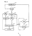
- FIG. 2 is a flowchart illustrating a method of controlling a hydroelectric plant 100 in accordance with an embodiment of the present invention.
- the control system 155 that implements the method 200 may be integrated with a graphical user interface (GUI), or the like.
- GUI graphical user interface
- the GUI may allow the operator to navigate through the method 200 described below.
- the GUI may also provide at least one notification of the status of the hydroelectric plant 100.
- the method 200 may be adapted to control the operation of a variety of configurations of hydroelectric plants 100.
- the hydroelectric plant 100 may be generating power.
- the power may comprise electricity for exporting to a grid system 165, mechanical torque, or combinations thereof.
- the method 200 may determine whether at least one permissive is satisfied.
- An embodiment of the present invention may require that the at least one permissive is satisfied before an embodiment of the algorithms of the adaptive MBC function.
- the permissive may generally be considered a requirement or preferred condition that confirms the hydroelectric plant 100 may use the adaptive MBC function.
- the user may define the at least one permissive.
- the at least one permissives may comprise a status of the hydroelectric plant, a status of a head feedback signal, a status of a generator megawatt feedback signal, a status of a servo-motor feedback signal, a generator frequency feedback signal, or combinations thereof. If the at least one initialization permissive is satisfied then the method 200 may proceed to step 215; otherwise the method 200 may revert to step 205 until the at least one initialization permissive is satisfied.
- the method 200 may receive a plurality of operating data.
- This data may comprise at least one of: command data or feedback data.
- the command data may comprise data on at least one of: a head setpoint, a generator output setpoint, a servo-motor demand setpoint, or combinations thereof.
- the feedback data may comprise data on at least one of: a head value, a generator megawatt value, a servo-motor position value, a generator frequency value, or combinations thereof.
- the method 210 may determine whether data from a previous operation of the adaptive MBC systems may be available. This information may be integrated into a current MBC model or may be used in the development of a new model MBC model. If model data is available then the method 200 may proceed to step 225; otherwise the method 200 may proceed to step 235.
- the method 200 may retrieve the model data.
- the method 200 may retrieve the model data from an internal memory, or the like.
- the method 200 may retrieve the mode data from an independent source.
- the method 200 may retrieve model data from model data storage, such as, but not limiting of, a library, or the like.
- the mode data may derive from an independent source, such as, but not limiting of, another system integrated with the control system 155.
- the method 200 may determine an output variable.
- the output variable may be considered a physical parameter, such as, but not limiting of, a generator output setpoint, a head setpoint, etc.
- the adaptive MBC algorithm of an embodiment of the present invention, may incorporate the plurality of operating data received in step 215 as inputs for updating an existing or for creating a new model.
- the model may determine a setting for the physical parameter.
- the adaptive MBC may incorporate input data such as, but not limiting of: generator output feedback, head, position of the at least one servo-motor 120.
- the adaptive MBC may use generator output setpoint, head, and the servo-motor position for the at least one opening 120 to estimate the feedback of the generator output.
- the adaptive MBC may then determine a setpoint for the at least one opening.
- the adaptive MBC may maintain frequency control of the generator 150 utilizing a droop control, isochronous control, or the like.
- the method 200 may store the current model processed by the adaptive MBC.
- the current model may be stored in internal memory.
- the current model may be stored in the model data storage as discussed in step 230.
- the method 200 may allow for aborting the operation of the adaptive MBC.
- the operation of the adaptive MBC may be aborted after the plurality of operating data 215 is received in step 215.
- An embodiment of the present invention may allow for a user to manually abort the operation of the adaptive MBC.
- the method 200 may be integrated with a system that allows for the automatic aborting of the operation of the adaptive MBC. If the operation of the adaptive MBC is aborted, then the method 200 may revert to step 205, otherwise the method 200 may proceed.
- step 250 the method 200 may determine whether at least one permissive is maintained during the operation of the adaptive MBC. Step 250 may be continuously monitoring the operation of the adaptive MBC.
- the GUI may notify the user if the permissive is not maintained.
- the method 200 may automatically revert to step 205 if the operational permissive is not maintained.
- FIG. 3 is a block diagram of an exemplary system 300 of controlling a hydroelectric plant in accordance with an embodiment of the present invention.
- the elements of the method 200 may be embodied in and performed by the system 300.
- the system 300 may include one or more user or client communication devices 302 or similar systems or devices (two are illustrated in Figure 3 ).
- Each communication device 302 may be for example, but not limited to, a computer system, a personal digital assistant, a cellular phone, or any device capable of sending and receiving an electronic message.
- the communication device 302 may include a system memory 304 or local file system.
- the system memory 304 may include for example, but is not limited to, a read only memory (ROM) and a random access memory (RAM).
- the ROM may include a basic input/output system (BIOS).
- BIOS may contain basic routines that help to transfer information between elements or components of the communication device 302.
- the system memory 304 may contain an operating system 306 to control overall operation of the communication device 302.
- the system memory 304 may also include a browser 308 or web browser.
- the system memory 304 may also include data structures 310 or computer-executable code for controlling a hydroelectric plant that may be similar or include elements of the method 200 in Figure 2 .
- the system memory 304 may further include a template cache memory 312, which may be used in conjunction with the method 200 in Figure 2 for controlling a hydroelectric plant.
- the communication device 302 may also include a processor or processing unit 314 to control operations of the other components of the communication device 302.
- the operating system 306, browser 308, and data structures 310 may be operable on the processing unit 314.
- the processing unit 314 may be coupled to the memory system 304 and other components of the communication device 302 by a system bus 316.
- the communication device 302 may also include multiple input devices (I/O), output devices or combination input/output devices 318. Each input/output device 318 may be coupled to the system bus 316 by an input/output interface (not shown in Figure 3 ).
- the input and output devices or combination I/O devices 318 permit a user to operate and interface with the communication device 302 and to control operation of the browser 308 and data structures 310 to access, operate and control the software to utilize a hydroelectric plant.
- the I/O devices 318 may include a keyboard and computer pointing device or the like to perform the operations discussed herein.
- the I/O devices 318 may also include for example, but are not limited to, disk drives, optical, mechanical, magnetic, or infrared input/output devices, modems or the like.
- the I/O devices 318 may be used to access a storage medium 320.
- the medium 320 may contain, store, communicate, or transport computer-readable or computer-executable instructions or other information for use by or in connection with a system, such as the communication devices 302.
- the communication device 302 may also include or be connected to other devices, such as a display or monitor 322.
- the monitor 322 may permit the user to interface with the communication device 302.
- the communication device 302 may also include a hard drive 324.
- the hard drive 324 may be coupled to the system bus 316 by a hard drive interface (not shown in Figure 3 ).
- the hard drive 324 may also form part of the local file system or system memory 304. Programs, software, and data may be transferred and exchanged between the system memory 304 and the hard drive 324 for operation of the communication device 302.
- the communication device 302 may communicate with at least one unit controller 326 and may access other servers or other communication devices similar to communication device 302 via a network 328.
- the system bus 316 may be coupled to the network 328 by a network interface 330.
- the network interface 330 may be a modem, Ethernet card, router, gateway, or the like for coupling to the network 328.
- the coupling may be a wired or wireless connection.
- the network 328 may be the Internet, private network, an intranet, or the like.
- the at least one unit controller 326 may also include a system memory 332 that may include a file system, ROM, RAM, and the like.
- the system memory 332 may include an operating system 334 similar to operating system 306 in communication devices 302.
- the system memory 332 may also include data structures 336 for controlling a hydroelectric plant.
- the data structures 336 may include operations similar to those described with respect to the method 200 for controlling a hydroelectric plant.
- the server system memory 332 may also include other files 338, applications, modules, and the like.
- the at least one unit controller 326 may also include a processor 342 or a processing unit to control operation of other devices in the at least one unit controller 326.
- the at least one unit controller 326 may also include I/O device 344.
- the I/O devices 344 may be similar to I/O devices 318 of communication devices 302.
- the at least one unit controller 326 may further include other devices 346, such as a monitor or the like to provide an interface along with the I/O devices 344 to the at least one unit controller 326.
- the at least one unit controller 326 may also include a hard disk drive 348.
- a system bus 350 may connect the different components of the at least one unit controller 326.
- a network interface 352 may couple the at least one unit controller 326 to the network 328 via the system bus 350.
- each step in the flowchart or step diagrams may represent a module, segment, or portion of code, which comprises one or more executable instructions for implementing the specified logical function(s).
- the functions noted in the step may occur out of the order noted in the figures. For example, two steps shown in succession may, in fact, be executed substantially concurrently, or the steps may sometimes be executed in the reverse order, depending upon the functionality involved.
- each step of the step diagrams and/or flowchart illustration, and combinations of steps in the step diagrams and/or flowchart illustration can be implemented by special purpose hardware-based systems which perform the specified functions or acts, or combinations of special purpose hardware and computer instructions.
Landscapes
- Physics & Mathematics (AREA)
- General Physics & Mathematics (AREA)
- Engineering & Computer Science (AREA)
- Automation & Control Theory (AREA)
- Control Of Eletrric Generators (AREA)
- Control Of Water Turbines (AREA)
Applications Claiming Priority (1)
| Application Number | Priority Date | Filing Date | Title |
|---|---|---|---|
| US12/330,877 US8082067B2 (en) | 2008-12-09 | 2008-12-09 | Method and system of controlling a hydroelectric plant |
Publications (2)
| Publication Number | Publication Date |
|---|---|
| EP2196875A2 true EP2196875A2 (de) | 2010-06-16 |
| EP2196875A3 EP2196875A3 (de) | 2014-06-25 |
Family
ID=42060640
Family Applications (1)
| Application Number | Title | Priority Date | Filing Date |
|---|---|---|---|
| EP09177286.3A Withdrawn EP2196875A3 (de) | 2008-12-09 | 2009-11-27 | Verfahren und System zur Steuerung eines Wasserkraftwerks mit einem adaptiven Model |
Country Status (4)
| Country | Link |
|---|---|
| US (1) | US8082067B2 (de) |
| EP (1) | EP2196875A3 (de) |
| BR (1) | BRPI0905065A2 (de) |
| CA (1) | CA2686366A1 (de) |
Families Citing this family (13)
| Publication number | Priority date | Publication date | Assignee | Title |
|---|---|---|---|---|
| FR2933878B1 (fr) * | 2008-07-18 | 2010-12-10 | Alstom Hydro France | Dispositif de separation de particules solides et installation hydraulique comprenant un tel dispositif |
| US20120086204A1 (en) * | 2010-10-11 | 2012-04-12 | Cla-Val Co. | System and method for controlled hydroelectric power generation |
| US8532834B2 (en) * | 2010-10-29 | 2013-09-10 | Hatch Ltd. | Method for integrating controls for captive power generation facilities with controls for metallurgical facilities |
| US8700221B2 (en) | 2010-12-30 | 2014-04-15 | Fluid Handling Llc | Method and apparatus for pump control using varying equivalent system characteristic curve, AKA an adaptive control curve |
| RU2611071C2 (ru) * | 2011-12-16 | 2017-02-21 | Флюид Хэндлинг ЭлЭлСи | Способ динамического линейного управления и устройство для управления насосом с переменной скоростью |
| US8823195B2 (en) * | 2012-04-03 | 2014-09-02 | Mark Robert John LEGACY | Hydro electric energy generation and storage structure |
| US8841787B1 (en) | 2013-03-15 | 2014-09-23 | Caterpillar Inc. | Generator set adaptive droop control method |
| EP3052807A4 (de) * | 2013-09-30 | 2017-06-28 | Eaton Corporation | Zahnradpumpe zur erzeugung von wasserkraft |
| US20190234369A1 (en) * | 2015-06-05 | 2019-08-01 | Ghing-Hsin Dien | Ocean current power generation system |
| CN110663153B (zh) * | 2017-04-13 | 2023-02-10 | 福伊特专利有限公司 | 用于调节电网频率的水力发电设备和用于运行的方法 |
| CN114784880A (zh) * | 2022-04-29 | 2022-07-22 | 广东电网有限责任公司 | 一种水电控制方法、装置、设备及存储介质 |
| US12612889B2 (en) | 2024-02-09 | 2026-04-28 | W.L. French Hydropower Holdings Llc | Modular hydropower systems and methods with pumped storage |
| US12612751B2 (en) * | 2024-02-09 | 2026-04-28 | W.L. French Hydropower Holdings Llc | Modular precast hydro dam with powerhouse |
Family Cites Families (6)
| Publication number | Priority date | Publication date | Assignee | Title |
|---|---|---|---|---|
| JPS6032036B2 (ja) * | 1975-08-13 | 1985-07-25 | 株式会社日立製作所 | 発電所の制御装置 |
| US4791309A (en) * | 1982-09-21 | 1988-12-13 | Thamesmead Engineering Limited | Electrical control systems |
| US4788647A (en) * | 1986-09-24 | 1988-11-29 | Digitek, Inc. | Control system for electric power plant |
| WO2006021125A1 (en) * | 2004-08-27 | 2006-03-02 | Eidgenössische Technische Hochschule Zürich | System for controlling hydroelectric power plants |
| US20070055392A1 (en) * | 2005-09-06 | 2007-03-08 | D Amato Fernando J | Method and system for model predictive control of a power plant |
| US20070225835A1 (en) * | 2006-03-23 | 2007-09-27 | Yucai Zhu | Computer method and apparatus for adaptive model predictive control |
-
2008
- 2008-12-09 US US12/330,877 patent/US8082067B2/en not_active Expired - Fee Related
-
2009
- 2009-11-26 CA CA2686366A patent/CA2686366A1/en not_active Abandoned
- 2009-11-27 EP EP09177286.3A patent/EP2196875A3/de not_active Withdrawn
- 2009-12-02 BR BRPI0905065-5A patent/BRPI0905065A2/pt not_active IP Right Cessation
Also Published As
| Publication number | Publication date |
|---|---|
| BRPI0905065A2 (pt) | 2011-02-08 |
| CA2686366A1 (en) | 2010-06-09 |
| US20100140934A1 (en) | 2010-06-10 |
| US8082067B2 (en) | 2011-12-20 |
| EP2196875A3 (de) | 2014-06-25 |
Similar Documents
| Publication | Publication Date | Title |
|---|---|---|
| US8082067B2 (en) | Method and system of controlling a hydroelectric plant | |
| WO2019050860A1 (en) | VARIABLE SPEED CONTROL OF A WIND GENERATOR BASED ON AN ESTIMATED COUPLE | |
| KR20190126402A (ko) | 수력 기계를 작동시키는 방법, 및 수력 에너지를 전기 에너지로 전환하는 상응하는 설비 | |
| Reigstad et al. | Nonlinear model predictive control of variable speed hydropower for provision of fast frequency reserves | |
| CN105927469B (zh) | 风力发电机组的限功率控制方法和控制装置 | |
| Shutari et al. | Towards enhancing the performance of grid-tied VSWT via adopting sine cosine algorithm-based optimal control scheme | |
| CN108280245B (zh) | 一种水轮机调速系统的阻尼特性分析方法 | |
| CN113991754B (zh) | 一种风电场的控制方法、系统及计算设备 | |
| Wang et al. | Model predictive control for power optimization in a hydrostatic wind turbine | |
| CN117543721B (zh) | 梯级水风光互补系统的优化调度方法、装置、设备及介质 | |
| Zhang et al. | Canal lock variable speed hydropower turbine design and control | |
| Kebede et al. | Power control of wind energy conversion system with doubly fed induction generator | |
| EP2508720B1 (de) | Verfahren zur Regelung eines Kraftwerks und System zur Erhöhung der operativen Flexibilität eines Kraftwerks | |
| CN120049534B (zh) | 自适应动能储能的大规模风电场最优减载控制方法及系统 | |
| EP2927434A1 (de) | System und verfahren zur steuerung einer turbinendrehzahl mit einem drehmomentwandler | |
| Talebi et al. | Fractional‐order back‐stepping sliding‐mode torque control for a wind energy conversion system | |
| Silva et al. | Convex model predictive control for down-regulation strategies in wind turbines | |
| Sahoo et al. | Design and simulation of a GA optimized variable speed DFIG based wind turbine using MATLAB | |
| Singh et al. | Frequency control for stand-alone hydro power plants using ant colony optimization | |
| US20140047840A1 (en) | Steam flow control system | |
| Lasheen et al. | Robust model predictive control for collective pitch in wind energy conversion systems | |
| CN109149654A (zh) | 确定跨区域水电-风电直流输电水电机组调节能力的方法 | |
| Nath et al. | Performance Analysis of AI Optimization Techniques for Control of OWC Energy Systems | |
| Landry et al. | Assessment of ancillary services contribution of a Kaplan turbine using different advanced technologies | |
| Bharti et al. | DFIG Based WT for Frequency Control along with AGC in Multi-Area Systems |
Legal Events
| Date | Code | Title | Description |
|---|---|---|---|
| PUAI | Public reference made under article 153(3) epc to a published international application that has entered the european phase |
Free format text: ORIGINAL CODE: 0009012 |
|
| AK | Designated contracting states |
Kind code of ref document: A2 Designated state(s): AT BE BG CH CY CZ DE DK EE ES FI FR GB GR HR HU IE IS IT LI LT LU LV MC MK MT NL NO PL PT RO SE SI SK SM TR |
|
| AX | Request for extension of the european patent |
Extension state: AL BA RS |
|
| PUAL | Search report despatched |
Free format text: ORIGINAL CODE: 0009013 |
|
| AK | Designated contracting states |
Kind code of ref document: A3 Designated state(s): AT BE BG CH CY CZ DE DK EE ES FI FR GB GR HR HU IE IS IT LI LT LU LV MC MK MT NL NO PL PT RO SE SI SK SM TR |
|
| AX | Request for extension of the european patent |
Extension state: AL BA RS |
|
| RIC1 | Information provided on ipc code assigned before grant |
Ipc: G05B 17/02 20060101AFI20140520BHEP |
|
| 17P | Request for examination filed |
Effective date: 20150105 |
|
| RBV | Designated contracting states (corrected) |
Designated state(s): AT BE BG CH CY CZ DE DK EE ES FI FR GB GR HR HU IE IS IT LI LT LU LV MC MK MT NL NO PL PT RO SE SI SK SM TR |
|
| STAA | Information on the status of an ep patent application or granted ep patent |
Free format text: STATUS: THE APPLICATION IS DEEMED TO BE WITHDRAWN |
|
| 18D | Application deemed to be withdrawn |
Effective date: 20150106 |