EP2196984A1 - Dispositif de terminal portable - Google Patents
Dispositif de terminal portable Download PDFInfo
- Publication number
- EP2196984A1 EP2196984A1 EP08836739A EP08836739A EP2196984A1 EP 2196984 A1 EP2196984 A1 EP 2196984A1 EP 08836739 A EP08836739 A EP 08836739A EP 08836739 A EP08836739 A EP 08836739A EP 2196984 A1 EP2196984 A1 EP 2196984A1
- Authority
- EP
- European Patent Office
- Prior art keywords
- display
- sub
- holder
- portable terminal
- terminal device
- Prior art date
- Legal status (The legal status is an assumption and is not a legal conclusion. Google has not performed a legal analysis and makes no representation as to the accuracy of the status listed.)
- Withdrawn
Links
- 230000006378 damage Effects 0.000 abstract description 12
- 239000012141 concentrate Substances 0.000 abstract description 2
- 239000004973 liquid crystal related substance Substances 0.000 description 6
- 229920003023 plastic Polymers 0.000 description 6
- 230000001902 propagating effect Effects 0.000 description 4
- 230000004075 alteration Effects 0.000 description 1
- 230000009977 dual effect Effects 0.000 description 1
- 230000002708 enhancing effect Effects 0.000 description 1
- 230000003116 impacting effect Effects 0.000 description 1
- 239000000463 material Substances 0.000 description 1
- 238000000034 method Methods 0.000 description 1
- 238000010295 mobile communication Methods 0.000 description 1
- 238000012986 modification Methods 0.000 description 1
- 230000004048 modification Effects 0.000 description 1
- 230000002265 prevention Effects 0.000 description 1
- 239000000126 substance Substances 0.000 description 1
Images








Classifications
-
- H—ELECTRICITY
- H04—ELECTRIC COMMUNICATION TECHNIQUE
- H04M—TELEPHONIC COMMUNICATION
- H04M1/00—Substation equipment, e.g. for use by subscribers
- H04M1/02—Constructional features of telephone sets
- H04M1/0202—Portable telephone sets, e.g. cordless phones, mobile phones or bar type handsets
- H04M1/026—Details of the structure or mounting of specific components
- H04M1/0266—Details of the structure or mounting of specific components for a display module assembly
-
- G—PHYSICS
- G02—OPTICS
- G02F—OPTICAL DEVICES OR ARRANGEMENTS FOR THE CONTROL OF LIGHT BY MODIFICATION OF THE OPTICAL PROPERTIES OF THE MEDIA OF THE ELEMENTS INVOLVED THEREIN; NON-LINEAR OPTICS; FREQUENCY-CHANGING OF LIGHT; OPTICAL LOGIC ELEMENTS; OPTICAL ANALOGUE/DIGITAL CONVERTERS
- G02F1/00—Devices or arrangements for the control of the intensity, colour, phase, polarisation or direction of light arriving from an independent light source, e.g. switching, gating or modulating; Non-linear optics
- G02F1/01—Devices or arrangements for the control of the intensity, colour, phase, polarisation or direction of light arriving from an independent light source, e.g. switching, gating or modulating; Non-linear optics for the control of the intensity, phase, polarisation or colour
- G02F1/13—Devices or arrangements for the control of the intensity, colour, phase, polarisation or direction of light arriving from an independent light source, e.g. switching, gating or modulating; Non-linear optics for the control of the intensity, phase, polarisation or colour based on liquid crystals, e.g. single liquid crystal display cells
- G02F1/133—Constructional arrangements; Operation of liquid crystal cells; Circuit arrangements
- G02F1/1333—Constructional arrangements; Manufacturing methods
- G02F1/133308—Support structures for LCD panels, e.g. frames or bezels
-
- H—ELECTRICITY
- H04—ELECTRIC COMMUNICATION TECHNIQUE
- H04M—TELEPHONIC COMMUNICATION
- H04M1/00—Substation equipment, e.g. for use by subscribers
- H04M1/02—Constructional features of telephone sets
- H04M1/18—Telephone sets specially adapted for use in ships, mines, or other places exposed to adverse environment
- H04M1/185—Improving the shock resistance of the housing, e.g. by increasing the rigidity
-
- G—PHYSICS
- G02—OPTICS
- G02F—OPTICAL DEVICES OR ARRANGEMENTS FOR THE CONTROL OF LIGHT BY MODIFICATION OF THE OPTICAL PROPERTIES OF THE MEDIA OF THE ELEMENTS INVOLVED THEREIN; NON-LINEAR OPTICS; FREQUENCY-CHANGING OF LIGHT; OPTICAL LOGIC ELEMENTS; OPTICAL ANALOGUE/DIGITAL CONVERTERS
- G02F1/00—Devices or arrangements for the control of the intensity, colour, phase, polarisation or direction of light arriving from an independent light source, e.g. switching, gating or modulating; Non-linear optics
- G02F1/01—Devices or arrangements for the control of the intensity, colour, phase, polarisation or direction of light arriving from an independent light source, e.g. switching, gating or modulating; Non-linear optics for the control of the intensity, phase, polarisation or colour
- G02F1/13—Devices or arrangements for the control of the intensity, colour, phase, polarisation or direction of light arriving from an independent light source, e.g. switching, gating or modulating; Non-linear optics for the control of the intensity, phase, polarisation or colour based on liquid crystals, e.g. single liquid crystal display cells
- G02F1/133—Constructional arrangements; Operation of liquid crystal cells; Circuit arrangements
- G02F1/1333—Constructional arrangements; Manufacturing methods
- G02F1/133308—Support structures for LCD panels, e.g. frames or bezels
- G02F1/133311—Environmental protection, e.g. against dust or humidity
-
- G—PHYSICS
- G02—OPTICS
- G02F—OPTICAL DEVICES OR ARRANGEMENTS FOR THE CONTROL OF LIGHT BY MODIFICATION OF THE OPTICAL PROPERTIES OF THE MEDIA OF THE ELEMENTS INVOLVED THEREIN; NON-LINEAR OPTICS; FREQUENCY-CHANGING OF LIGHT; OPTICAL LOGIC ELEMENTS; OPTICAL ANALOGUE/DIGITAL CONVERTERS
- G02F1/00—Devices or arrangements for the control of the intensity, colour, phase, polarisation or direction of light arriving from an independent light source, e.g. switching, gating or modulating; Non-linear optics
- G02F1/01—Devices or arrangements for the control of the intensity, colour, phase, polarisation or direction of light arriving from an independent light source, e.g. switching, gating or modulating; Non-linear optics for the control of the intensity, phase, polarisation or colour
- G02F1/13—Devices or arrangements for the control of the intensity, colour, phase, polarisation or direction of light arriving from an independent light source, e.g. switching, gating or modulating; Non-linear optics for the control of the intensity, phase, polarisation or colour based on liquid crystals, e.g. single liquid crystal display cells
- G02F1/133—Constructional arrangements; Operation of liquid crystal cells; Circuit arrangements
- G02F1/1333—Constructional arrangements; Manufacturing methods
- G02F1/133308—Support structures for LCD panels, e.g. frames or bezels
- G02F1/133314—Back frames
-
- G—PHYSICS
- G02—OPTICS
- G02F—OPTICAL DEVICES OR ARRANGEMENTS FOR THE CONTROL OF LIGHT BY MODIFICATION OF THE OPTICAL PROPERTIES OF THE MEDIA OF THE ELEMENTS INVOLVED THEREIN; NON-LINEAR OPTICS; FREQUENCY-CHANGING OF LIGHT; OPTICAL LOGIC ELEMENTS; OPTICAL ANALOGUE/DIGITAL CONVERTERS
- G02F1/00—Devices or arrangements for the control of the intensity, colour, phase, polarisation or direction of light arriving from an independent light source, e.g. switching, gating or modulating; Non-linear optics
- G02F1/01—Devices or arrangements for the control of the intensity, colour, phase, polarisation or direction of light arriving from an independent light source, e.g. switching, gating or modulating; Non-linear optics for the control of the intensity, phase, polarisation or colour
- G02F1/13—Devices or arrangements for the control of the intensity, colour, phase, polarisation or direction of light arriving from an independent light source, e.g. switching, gating or modulating; Non-linear optics for the control of the intensity, phase, polarisation or colour based on liquid crystals, e.g. single liquid crystal display cells
- G02F1/133—Constructional arrangements; Operation of liquid crystal cells; Circuit arrangements
- G02F1/1333—Constructional arrangements; Manufacturing methods
- G02F1/133308—Support structures for LCD panels, e.g. frames or bezels
- G02F1/133317—Intermediate frames, e.g. between backlight housing and front frame
-
- G—PHYSICS
- G02—OPTICS
- G02F—OPTICAL DEVICES OR ARRANGEMENTS FOR THE CONTROL OF LIGHT BY MODIFICATION OF THE OPTICAL PROPERTIES OF THE MEDIA OF THE ELEMENTS INVOLVED THEREIN; NON-LINEAR OPTICS; FREQUENCY-CHANGING OF LIGHT; OPTICAL LOGIC ELEMENTS; OPTICAL ANALOGUE/DIGITAL CONVERTERS
- G02F1/00—Devices or arrangements for the control of the intensity, colour, phase, polarisation or direction of light arriving from an independent light source, e.g. switching, gating or modulating; Non-linear optics
- G02F1/01—Devices or arrangements for the control of the intensity, colour, phase, polarisation or direction of light arriving from an independent light source, e.g. switching, gating or modulating; Non-linear optics for the control of the intensity, phase, polarisation or colour
- G02F1/13—Devices or arrangements for the control of the intensity, colour, phase, polarisation or direction of light arriving from an independent light source, e.g. switching, gating or modulating; Non-linear optics for the control of the intensity, phase, polarisation or colour based on liquid crystals, e.g. single liquid crystal display cells
- G02F1/133—Constructional arrangements; Operation of liquid crystal cells; Circuit arrangements
- G02F1/1333—Constructional arrangements; Manufacturing methods
- G02F1/133342—Constructional arrangements; Manufacturing methods for double-sided displays
-
- G—PHYSICS
- G02—OPTICS
- G02F—OPTICAL DEVICES OR ARRANGEMENTS FOR THE CONTROL OF LIGHT BY MODIFICATION OF THE OPTICAL PROPERTIES OF THE MEDIA OF THE ELEMENTS INVOLVED THEREIN; NON-LINEAR OPTICS; FREQUENCY-CHANGING OF LIGHT; OPTICAL LOGIC ELEMENTS; OPTICAL ANALOGUE/DIGITAL CONVERTERS
- G02F2201/00—Constructional arrangements not provided for in groups G02F1/00 - G02F7/00
- G02F2201/50—Protective arrangements
- G02F2201/503—Arrangements improving the resistance to shock
Definitions
- the present invention relates to a portable terminal device in which display means, such as a liquid crystal display device, is provided on both sides of an enclosure and, more particularly, to a portable terminal device in which a large so-called main display is provided on one side of an enclosure and a small so-called sub-display is provided on the other side.
- display means such as a liquid crystal display device
- a commercialized portable terminal device like a related-art folded portable phone, has a main display that provides various displays when enclosures are opened and a sub-display that displays an incoming call status and a time even when the enclosures are folded.
- the related-art portable terminal device is convenient because the device makes it possible to check an incoming call status and a time with enclosures being folded.
- the portable terminal is held in a pocket or a bag or carried in one hand while folded. Therefore, the enclosures of the portable terminal device are sometimes pressed or dropped to a floor as a result of a user taking a seat while the portable terminal device is held in a pants pocket.
- force exerted on the sub-display that is situated on an exterior side with the enclosures being folded is transmitted directly to the main display, thereby deforming the main display. In an extreme case, the main display is sometimes destroyed.
- the main display and the sub-display are separated apart from each other at a given interval.
- a bracket is interposed between the displays so as to support the sub-display while protecting and covering the main LCD.
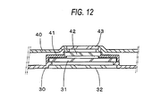
- Fig. 12 shows a cross-sectional view of the related-art portable terminal device.
- reference numeral 30 designates a main display enclosure
- reference numeral 40 designates a sub-display enclosure
- Reference numeral 41 designates a bracket for fixedly holding the main display and the sub-display spaced apart from each other at a given interval.
- Reference numeral 31 designates a main display
- reference numeral 42 designates a sub-display.
- the main display enclosure 30 is provided with a main display transparent window 32
- the sub-display enclosure 40 is provided with a sub-display transparent window 43.
- the main display 31 and the sub-display 42 are held in the main display enclosure 30 and the sub-display enclosure 40 while separated apart from each other by a predetermined space by means of a bracket 41. Since the main display 31 and the sub-display 42 are separated apart from each other by a predetermined interval, the main display 31 and the sub-display 42 do not contact each other even when impact force is exerted on the portable terminal device.
- the bracket 41 receives the force exerted on the sub-display provided in the exterior side. Even the related-art portable terminal device can thereby prevent deformation or destruction of the main display (see; for instance, Patent Document 1).
- a method for receiving force exerted on the sub-display conceived as another related-art example is to bring a planar component of material substance, such as a printed board, into contact with an undersurface of the sub-display in place of providing space between the main display and the sub-display, as show in Fig. 13.
- Fig. 13 shows a cross-sectional view of enclosures equipped with a main display and a sub-display of another related-art portable terminal device.
- reference numeral 50 designates a main display enclosure, and the main display enclosure is overlaid on a sub-display enclosure 60 in its vertical direction.
- the main display enclosure 50 is provided with a backlight reflection plate 51 made of a stainless plate having a thickness of about 0.3 mm, and a light guide plate 54 made of a transparent plastic plate and a main display 55 made of a liquid-crystal plate are attached to a position below the back light reflection plate 51 by means of a main display holder 53.
- a main display panel 56 made of a transparent plastic plate is attached to the main display enclosure 50.
- a printed board 52 is placed on the previously-described back light reflection plate 51, and a sub-display holder 61 previously provided with a sub-display 62 made of a liquid crystal plate is fixed onto the printed board 52.
- a dustproof sponge 63 is provided around an upper surface of the sub-display 62.
- the sub-display enclosure 60 is overlaid so as to press the sponge 63.
- a sub-display panel 64 made of a transparent plastic plate is attached to the sub-display enclosure 60.
- Patent Document 1 JP-A-2006-227627
- a challenge to be met by the present invention is to implement a portable terminal device that includes a main display provided on one side of an enclosure and a sub-display provided on the other side of the same and that prevents deformation or break of the main display, which would otherwise be caused as a result of force being exerted on the sub-display in an exterior side with the enclosures folded.
- a bottom portion of the sub-display holder is provided with a tapered surface that is shallowly tapered toward the outside of the holder. Pressing force propagating from the bottom portion of the holder of the sub-display to the main display when the portable terminal device is pressed is thereby dispersed, to thus prevent deformation or destruction of the main display.
- corners of a bottom portion of the sub-display holder are made round. Pressing force propagating from the corner of the bottom portion of the holder of the sub-display to the main display when the portable terminal device is pressed is thereby dispersed, to thus prevent deformation or destruction of the main display.
- the sub-display holder has a frame and a back plate straddling the frame.
- the rigidity of the holder of the sub-display is thereby enhanced, and an amount of deformation developing when the pressing force is exerted on the holder of the sub-display is reduced.
- the present invention makes it possible to prevent deformation or destruction of the main display even when the sub-display and the main display come close to each other as a result of the enclosures of the portable terminal device being pressed.
- Fig. 1 shows an external perspective view of a portable phone 100 that is a portable terminal device of a first embodiment of the present invention.
- Fig. 1 shows a closed state of the folded portable phone 100.
- a first enclosure 1 provided with an unillustrated operation section, such as a ten key
- a second enclosure 2 provided with two display sections; namely, a main display and a sub-display, are jointed together so as to be reclosable in a direction of arrow A by means of a hinge 3.
- the sub-display panel 6 is visible in a folded state of the folded portable phone 100.
- a sub-display 5 held by a sub-display holder 4 indicated by a broken line is disposed beneath the sub-display panel 6.
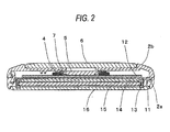
- Fig. 2 shows a cross-sectional view of the second enclosure 2 of the folded portable phone 100.
- reference numeral 2a designates a main display enclosure, and the main display enclosure 2a is overlaid on a sub-display enclosure 2b in its vertical direction.
- the main display enclosure 2a is provided with a backlight reflection plate 11 made up of a stainless plate having a thickness of about 0.3 mm.
- a light guide plate 14 made of a transparent plastic plate and a main display 15 made of a liquid crystal plate are attached to respective positions below the backlight reflection plate 11 by means of the main display holder 13.
- a main display panel 16 made of a transparent plastic plate is attached to the main display enclosure 2a.
- the foregoing structure is identical with the structure of the related-art portable terminal device shown in Fig. 13 .
- the printed board 12 is placed on the backlight reflection plate 11.
- the sub-display holder 4 provided with the sub-display 5 made of a liquid crystal plate is previously fastened onto the printed board 12.
- a dustproof sponge 7 is provided around an upper surface of the sub-display 5.
- the sub-display enclosure 2b is overlaid so as to press the sponge 7.
- a sub-display panel 6 made of a transparent plastic plate is attached to the sub-display enclosure 2b.
- the foregoing structure is also identical with the structure of the related-art portable terminal device shown in Fig. 13 .
- the portable terminal device of the first embodiment is characterized by the shape of the sub-display holder 4.
- Fig. 3 shows an exploded perspective view of the sub-display holder 4 and the sub-display 5 of the first embodiment when viewed from an upper oblique direction.
- the sub-display 5 is overlaid on the sub-display holder 4 in the direction of arrow B.
- the shape of the sub-display holder 4 is described.
- the sub-display holder 4 is a square frame 4a, and supports 4b for receiving the sub-display 5 are formed at respective four internal corners of the frame 4a.
- a pair of ribs 4c are provided along one interior side of the frame 4a, and a pair of side pressure arms 4d for pressing a side surface of the sub-display 5 are provided on an opposite side.
- a lift prevention rib 4e is formed on each of the side pressure arms 4d.
- the sub-display 5 When attached to the sub-display holder, the sub-display 5 is at one end pressed against the side pressure arm 4d and is hooked at the other end on the rib 4c.
- Reference numeral 4f designates a fastening section with a screw hole, and an un-illustrated screw is inserted into the screw hole 4f, thereby fixing the printed board.
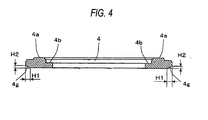
- Fig. 4 shows a cross-sectional view of the sub-display holder 4 of the portable terminal device of the first embodiment taken along line C-C shown in Fig. 3 .
- reference numeral 4a designates a frame
- 4b designates a support.
- An undersurface of the sub-display holder 4 becomes thinner toward the outside in a tapered fashion as indicated by reference numeral 4g.
- a shallow taper is determined by a dimension H2 of the order of 0.2 provided that a dimension H1 shown in Fig. 4 is taken as one.
- the respective corners in the cross section are illustrated as being pointed in Fig. 4 , the corners are, in reality, made round and finished into curved surfaces.
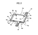
- Fig. 5 is an oblique perspective view of the sub-display holder 4 of the first embodiment achieved when the holder is turned inside out.
- An entire circumference of the undersurface of the sub-display holder 4 is tapered, to thus make up a tapered surface 4g.
- a circumference of each of the fixing sections 4f also makes up a tapered surface.
- a small arrow shown in Fig. 5 designates the orientation of the slope of the tapered surface 4g.
- Fig. 6 is a partially enlarged view of the oblique perspective view of the sub-display holder 4 of the first embodiment achieved when the sub-display holder 4 is turned inside out.
- the drawing shows that each of the corners of the undersurface of the sub-display holder 4 is made round, to thus assume a round shape.
- Fig. 7 again shows a cross-sectional profile of the second enclosure 2 of the folded portable phone 100, wherein there is illustrated a state achieved when the sub-display panel 6 starts undergoing a press in a direction of arrow D.
- Pressing force exerted in the direction of arrow D propagates from the sub-display panel 6 to the sub-display enclosure 2b and further from the sub-display enclosure 2b to the sub-display holder 4.
- Pressing force propagates from the sub-display holder 4 to the printed board 12 located beneath the sub-display holder as indicated by arrow E.
- the undersurface of the sub-display holder 4 is made thin in a tapered fashion toward the outside.
- the tapered surface 4g that is an undersurface of the sub-display holder 4 comes into contact with the printed board. Since the tapered surface 4g and the printed board establish plane contact, the force exerted on the printed board 12 does not concentrate on the corners (edges) and becomes dispersed. Pressure developing between the tapered surface 4g and the printed board 12 comes to a small value. Pressure does not act intensively on the backlight reflection plate 11, the light guide plate 14, and the main display 15 that are located closer to the main display side than is the printed board 12. Deformation or destruction of the main display, which would otherwise be caused as a result of the sub-display and the main display coming close to each other when the enclosures of the folded portable terminal device are pressed, is prevented.
- the second embodiment of the present invention is characterized in that the sub-display holder is provided with a back plate that straddles the frame.
- the rigidity of the sub-display holder is enhanced by provision of the back plate, thereby reducing an amount of deformation generated when pressing force is exerted on the sub-display holder.
- Fig. 8 shows an exploded perspective view of the sub-display holder 20 and the sub-display 5 of the second embodiment achieved when they are obliquely viewed from an elevated position.
- the sub-display 5 is overlaid on the sub-display holder 20 in the direction of arrow B in the same manner as that shown in Fig. 3 .
- the basic configuration of the sub-display holder 20 is also identical with the basic configuration of its counterpart sub-display holder shown in Fig. 3 .
- the sub-display holder 20 shown in Fig. 8 is provided with a back plate 20h for enhancing the rigidity of the sub-display holder, to thus prevent deformation of the frame 20a.
- the other portion of the sub-display holder 20 is basically identical with its counterpart of the sub-display holder 4 of the first embodiment ( Fig. 3 ) except the portion particularly given explanations.
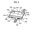
- Fig. 9 is an oblique perspective view of the sub-display holder 20 of the second embodiment when the sub-display holder is turned inside out.
- the back plate 20h is provided on the frame 20a of the sub-display holder 20. The presence of the back plate 20h results in an increase in section modulus, which in turn makes the frame 20a less susceptible to deformation.
- Fig. 10 shows a cross-sectional view of the second enclosure 2 of the folded portable phone of the second embodiment of the present invention.
- Fig. 10 shows that the printed board is divided into two sub-divisions 22a and 22b and that a back plate 20h of the sub-display holder 20 is housed in space between the sub-divisions.
- Fig. 11 again shows a cross-sectional view of the second enclosure 2 of the folded portable phone of the second embodiment of the present invention and also shows a state in which the sub-display panel 6 starts undergoing a press in the direction of arrow D.
- the pressing force exerted in the direction of arrow D propagates from the sub-display panel 6 to the sub-display enclosure 2b and further from the sub-display enclosure 2b to the sub-display holder 20.
- the rigidity of the sub-display holder 20 of the second embodiment is enhanced by the back plate 20h and hence is less susceptible to deformation, and force is transmitted to the printed board 22b while the sub-display holder 20 is held flat. Therefore, even when the sub-display and the main display come close to each other as a result of the enclosures of the folded portable terminal device being pressed, deformation or break of the main display is further prevented.
- the display holder 20 When subjected to deformation at the time of exertion of pressing force, the display holder 20 becomes deformed. However, even if the display holder 20 has become deformed, the tapered surface 20g that is an undersurface of the display holder 20 will contact the printed board 22b. Hence, pressing force does not act intensively on the backlight reflection plate 11, the light guide plate 14, and the main display 15 that are located closer to the main display side than is the printed board 12. Deformation or destruction of the main display can therefor be prevented even when pressing force exerts on the main display in an impacting manner.
- the first embodiment and the second embodiment have stated the example in which the bottom portion of the sub-display holder is given a shallow tapered shape; however, the bottom portion of the sub-display holder can also be given a round shape instead,
- the pressing force propagating from the bottom portion of the sub-display holder to the main display is dispersed, thereby making it possible to prevent deformation or destruction of the main display.
- holes can be opened in a structure located beneath the corners of the bottom portion of the sub-display holder in place of or in addition to the round corners.
- the present invention can be applied to another portable terminal device including a main display provided on one side of an enclosure and a sub-display provided on the other side of the same, such as a portable phone, a PDA (Personal Digital Assistants or a portable information terminal), a notebook personal computer, and a portable game machine.
- a portable phone a PDA (Personal Digital Assistants or a portable information terminal)
- a notebook personal computer a notebook personal computer
- a portable game machine such as a portable game machine.
Landscapes
- Physics & Mathematics (AREA)
- Nonlinear Science (AREA)
- Signal Processing (AREA)
- Engineering & Computer Science (AREA)
- Mathematical Physics (AREA)
- Crystallography & Structural Chemistry (AREA)
- Chemical & Material Sciences (AREA)
- General Physics & Mathematics (AREA)
- Optics & Photonics (AREA)
- Telephone Set Structure (AREA)
- Liquid Crystal (AREA)
- Devices For Indicating Variable Information By Combining Individual Elements (AREA)
- Casings For Electric Apparatus (AREA)
Applications Claiming Priority (2)
| Application Number | Priority Date | Filing Date | Title |
|---|---|---|---|
| JP2007259609A JP2009089304A (ja) | 2007-10-03 | 2007-10-03 | 携帯端末装置 |
| PCT/JP2008/002136 WO2009044499A1 (fr) | 2007-10-03 | 2008-08-06 | Dispositif de terminal portable |
Publications (1)
| Publication Number | Publication Date |
|---|---|
| EP2196984A1 true EP2196984A1 (fr) | 2010-06-16 |
Family
ID=40525932
Family Applications (1)
| Application Number | Title | Priority Date | Filing Date |
|---|---|---|---|
| EP08836739A Withdrawn EP2196984A1 (fr) | 2007-10-03 | 2008-08-06 | Dispositif de terminal portable |
Country Status (4)
| Country | Link |
|---|---|
| EP (1) | EP2196984A1 (fr) |
| JP (1) | JP2009089304A (fr) |
| CN (1) | CN101816027A (fr) |
| WO (1) | WO2009044499A1 (fr) |
Cited By (2)
| Publication number | Priority date | Publication date | Assignee | Title |
|---|---|---|---|---|
| US9720269B2 (en) | 2013-02-21 | 2017-08-01 | Lg Electronics Inc. | Display device |
| FR3115611A1 (fr) * | 2020-10-26 | 2022-04-29 | Valeo Comfort And Driving Assistance | Dispositif d’assemblage adapté pour assembler un écran avec un élément partiellement transparent et afficheur tête haute comprenant un tel dispositif |
Families Citing this family (2)
| Publication number | Priority date | Publication date | Assignee | Title |
|---|---|---|---|---|
| KR101515629B1 (ko) | 2012-01-07 | 2015-04-27 | 삼성전자주식회사 | 플렉서블 표시부를 갖는 휴대단말의 이벤트 제공 방법 및 장치 |
| KR101584590B1 (ko) | 2013-07-11 | 2016-01-13 | 삼성전자주식회사 | 어플리케이션을 표시하는 사용자 단말 장치 및 그 방법 |
Family Cites Families (10)
| Publication number | Priority date | Publication date | Assignee | Title |
|---|---|---|---|---|
| JP2004112659A (ja) * | 2002-09-20 | 2004-04-08 | Nec Access Technica Ltd | 折畳み式携帯電話 |
| JP2004151551A (ja) * | 2002-10-31 | 2004-05-27 | Seiko Epson Corp | 電気光学パネル、電気光学パネルの保持構造、電気光学装置、電気光学パネルの製造方法及び電気光学装置の製造方法 |
| JP2004271839A (ja) * | 2003-03-07 | 2004-09-30 | Toshiba Matsushita Display Technology Co Ltd | 両面表示用液晶表示モジュール |
| JP2005189512A (ja) * | 2003-12-25 | 2005-07-14 | Nec Corp | 電子機器における背面lcdの衝撃吸収構造および該構造を備えた電子機器 |
| JP4689304B2 (ja) * | 2004-06-29 | 2011-05-25 | パナソニック株式会社 | 液晶表示装置 |
| KR100631193B1 (ko) * | 2004-10-27 | 2006-10-04 | 삼성전자주식회사 | 디스플레이장치 및 그것을 구비하는 휴대폰 |
| KR100677747B1 (ko) | 2005-02-18 | 2007-02-02 | 삼성전자주식회사 | 이동통신 단말기용 듀얼형 lcd 모듈 |
| JP4511408B2 (ja) * | 2005-04-18 | 2010-07-28 | 富士通株式会社 | 表示モジュールおよび携帯端末装置 |
| JP2007033658A (ja) * | 2005-07-25 | 2007-02-08 | Fujitsu Ltd | 情報処理装置 |
| JP4856999B2 (ja) | 2006-03-24 | 2012-01-18 | 日立アプライアンス株式会社 | モータ |
-
2007
- 2007-10-03 JP JP2007259609A patent/JP2009089304A/ja active Pending
-
2008
- 2008-08-06 CN CN200880110071A patent/CN101816027A/zh active Pending
- 2008-08-06 EP EP08836739A patent/EP2196984A1/fr not_active Withdrawn
- 2008-08-06 WO PCT/JP2008/002136 patent/WO2009044499A1/fr not_active Ceased
Non-Patent Citations (1)
| Title |
|---|
| See references of WO2009044499A1 * |
Cited By (3)
| Publication number | Priority date | Publication date | Assignee | Title |
|---|---|---|---|---|
| US9720269B2 (en) | 2013-02-21 | 2017-08-01 | Lg Electronics Inc. | Display device |
| FR3115611A1 (fr) * | 2020-10-26 | 2022-04-29 | Valeo Comfort And Driving Assistance | Dispositif d’assemblage adapté pour assembler un écran avec un élément partiellement transparent et afficheur tête haute comprenant un tel dispositif |
| WO2022090233A1 (fr) * | 2020-10-26 | 2022-05-05 | Valeo Comfort And Driving Assistance | Dispositif d'assemblage adapté pour assembler un écran avec un élément partiellement transparent et afficheur tête haute comprenant un tel dispositif |
Also Published As
| Publication number | Publication date |
|---|---|
| CN101816027A (zh) | 2010-08-25 |
| JP2009089304A (ja) | 2009-04-23 |
| WO2009044499A1 (fr) | 2009-04-09 |
Similar Documents
| Publication | Publication Date | Title |
|---|---|---|
| EP1621968B1 (fr) | Structure de protection de dispositif d'affichage à cristaux liquides pour équipement électronique | |
| EP2262203B1 (fr) | Module d'affichage à cristaux liquides et terminal portable | |
| US20050243239A1 (en) | Display device | |
| EP2196984A1 (fr) | Dispositif de terminal portable | |
| JP3716216B2 (ja) | 電子機器の背面lcd固定構造 | |
| EP1548492B1 (fr) | Structure d'absorption des chocs d'un afficheur arrière à cristaux liquides d'un appareil électronique et appareil électronique ayant cette structure | |
| JP4405532B2 (ja) | 折畳み式携帯電話機 | |
| EP2189965B1 (fr) | Dispositif electronique et cadre | |
| US8934623B2 (en) | Housing for electronic device | |
| JP6322908B2 (ja) | 表示装置および表示支持装置 | |
| JP4802809B2 (ja) | 両面表示型液晶モジュール | |
| JP2006119299A (ja) | 携帯機器 | |
| JP4063579B2 (ja) | 携帯通信機器 | |
| US20060256514A1 (en) | Pressure resistance cover for the display panel of a portable computer | |
| JP4432424B2 (ja) | 液晶表示装置および電子機器 | |
| US20090244434A1 (en) | Electronic device and liquid crystal display | |
| JP4994114B2 (ja) | 携帯端末装置 | |
| JP5451061B2 (ja) | 表示デバイス保護構造 | |
| JP2007171738A (ja) | 液晶モジュール | |
| JP2005173393A (ja) | 液晶表示装置および電子機器 | |
| JP5111905B2 (ja) | 電子機器 | |
| JP2008263347A (ja) | 電子機器 | |
| US20220100020A1 (en) | Display Device | |
| JP2007086672A (ja) | 液晶モジュール | |
| JP2009037113A (ja) | 画像表示装置 |
Legal Events
| Date | Code | Title | Description |
|---|---|---|---|
| PUAI | Public reference made under article 153(3) epc to a published international application that has entered the european phase |
Free format text: ORIGINAL CODE: 0009012 |
|
| 17P | Request for examination filed |
Effective date: 20100406 |
|
| AK | Designated contracting states |
Kind code of ref document: A1 Designated state(s): AT BE BG CH CY CZ DE DK EE ES FI FR GB GR HR HU IE IS IT LI LT LU LV MC MT NL NO PL PT RO SE SI SK TR |
|
| AX | Request for extension of the european patent |
Extension state: AL BA MK RS |
|
| STAA | Information on the status of an ep patent application or granted ep patent |
Free format text: STATUS: THE APPLICATION HAS BEEN WITHDRAWN |
|
| 18W | Application withdrawn |
Effective date: 20100616 |