EP2197068B1 - Dispositif et procédé de production d'énergie mécanique et électrique - Google Patents
Dispositif et procédé de production d'énergie mécanique et électrique Download PDFInfo
- Publication number
- EP2197068B1 EP2197068B1 EP09176287A EP09176287A EP2197068B1 EP 2197068 B1 EP2197068 B1 EP 2197068B1 EP 09176287 A EP09176287 A EP 09176287A EP 09176287 A EP09176287 A EP 09176287A EP 2197068 B1 EP2197068 B1 EP 2197068B1
- Authority
- EP
- European Patent Office
- Prior art keywords
- fuel
- target fraction
- hydrogen
- fraction
- heat engine
- Prior art date
- Legal status (The legal status is an assumption and is not a legal conclusion. Google has not performed a legal analysis and makes no representation as to the accuracy of the status listed.)
- Active
Links
Images

Classifications
-
- H—ELECTRICITY
- H01—ELECTRIC ELEMENTS
- H01M—PROCESSES OR MEANS, e.g. BATTERIES, FOR THE DIRECT CONVERSION OF CHEMICAL ENERGY INTO ELECTRICAL ENERGY
- H01M8/00—Fuel cells; Manufacture thereof
- H01M8/06—Combination of fuel cells with means for production of reactants or for treatment of residues
- H01M8/0606—Combination of fuel cells with means for production of reactants or for treatment of residues with means for production of gaseous reactants
- H01M8/0612—Combination of fuel cells with means for production of reactants or for treatment of residues with means for production of gaseous reactants from carbon-containing material
-
- B—PERFORMING OPERATIONS; TRANSPORTING
- B60—VEHICLES IN GENERAL
- B60L—PROPULSION OF ELECTRICALLY-PROPELLED VEHICLES; SUPPLYING ELECTRIC POWER FOR AUXILIARY EQUIPMENT OF ELECTRICALLY-PROPELLED VEHICLES; ELECTRODYNAMIC BRAKE SYSTEMS FOR VEHICLES IN GENERAL; MAGNETIC SUSPENSION OR LEVITATION FOR VEHICLES; MONITORING OPERATING VARIABLES OF ELECTRICALLY-PROPELLED VEHICLES; ELECTRIC SAFETY DEVICES FOR ELECTRICALLY-PROPELLED VEHICLES
- B60L50/00—Electric propulsion with power supplied within the vehicle
- B60L50/50—Electric propulsion with power supplied within the vehicle using propulsion power supplied by batteries or fuel cells
- B60L50/70—Electric propulsion with power supplied within the vehicle using propulsion power supplied by batteries or fuel cells using power supplied by fuel cells
- B60L50/72—Constructional details of fuel cells specially adapted for electric vehicles
-
- B—PERFORMING OPERATIONS; TRANSPORTING
- B60—VEHICLES IN GENERAL
- B60L—PROPULSION OF ELECTRICALLY-PROPELLED VEHICLES; SUPPLYING ELECTRIC POWER FOR AUXILIARY EQUIPMENT OF ELECTRICALLY-PROPELLED VEHICLES; ELECTRODYNAMIC BRAKE SYSTEMS FOR VEHICLES IN GENERAL; MAGNETIC SUSPENSION OR LEVITATION FOR VEHICLES; MONITORING OPERATING VARIABLES OF ELECTRICALLY-PROPELLED VEHICLES; ELECTRIC SAFETY DEVICES FOR ELECTRICALLY-PROPELLED VEHICLES
- B60L58/00—Methods or circuit arrangements for monitoring or controlling batteries or fuel cells, specially adapted for electric vehicles
- B60L58/30—Methods or circuit arrangements for monitoring or controlling batteries or fuel cells, specially adapted for electric vehicles for monitoring or controlling fuel cells
- B60L58/32—Methods or circuit arrangements for monitoring or controlling batteries or fuel cells, specially adapted for electric vehicles for monitoring or controlling fuel cells for controlling the temperature of fuel cells, e.g. by controlling the electric load
- B60L58/33—Methods or circuit arrangements for monitoring or controlling batteries or fuel cells, specially adapted for electric vehicles for monitoring or controlling fuel cells for controlling the temperature of fuel cells, e.g. by controlling the electric load by cooling
-
- B—PERFORMING OPERATIONS; TRANSPORTING
- B60—VEHICLES IN GENERAL
- B60W—CONJOINT CONTROL OF VEHICLE SUB-UNITS OF DIFFERENT TYPE OR DIFFERENT FUNCTION; CONTROL SYSTEMS SPECIALLY ADAPTED FOR HYBRID VEHICLES; ROAD VEHICLE DRIVE CONTROL SYSTEMS FOR PURPOSES NOT RELATED TO THE CONTROL OF A PARTICULAR SUB-UNIT
- B60W10/00—Conjoint control of vehicle sub-units of different type or different function
- B60W10/28—Conjoint control of vehicle sub-units of different type or different function including control of fuel cells
-
- B—PERFORMING OPERATIONS; TRANSPORTING
- B60—VEHICLES IN GENERAL
- B60K—ARRANGEMENT OR MOUNTING OF PROPULSION UNITS OR OF TRANSMISSIONS IN VEHICLES; ARRANGEMENT OR MOUNTING OF PLURAL DIVERSE PRIME-MOVERS IN VEHICLES; AUXILIARY DRIVES FOR VEHICLES; INSTRUMENTATION OR DASHBOARDS FOR VEHICLES; ARRANGEMENTS IN CONNECTION WITH COOLING, AIR INTAKE, GAS EXHAUST OR FUEL SUPPLY OF PROPULSION UNITS IN VEHICLES
- B60K6/00—Arrangement or mounting of plural diverse prime-movers for mutual or common propulsion, e.g. hybrid propulsion systems comprising electric motors and internal combustion engines
- B60K6/20—Arrangement or mounting of plural diverse prime-movers for mutual or common propulsion, e.g. hybrid propulsion systems comprising electric motors and internal combustion engines the prime-movers consisting of electric motors and internal combustion engines, e.g. HEVs
- B60K6/22—Arrangement or mounting of plural diverse prime-movers for mutual or common propulsion, e.g. hybrid propulsion systems comprising electric motors and internal combustion engines the prime-movers consisting of electric motors and internal combustion engines, e.g. HEVs characterised by apparatus, components or means specially adapted for HEVs
- B60K6/32—Arrangement or mounting of plural diverse prime-movers for mutual or common propulsion, e.g. hybrid propulsion systems comprising electric motors and internal combustion engines the prime-movers consisting of electric motors and internal combustion engines, e.g. HEVs characterised by apparatus, components or means specially adapted for HEVs characterised by the fuel cells
-
- H—ELECTRICITY
- H01—ELECTRIC ELEMENTS
- H01M—PROCESSES OR MEANS, e.g. BATTERIES, FOR THE DIRECT CONVERSION OF CHEMICAL ENERGY INTO ELECTRICAL ENERGY
- H01M2250/00—Fuel cells for particular applications; Specific features of fuel cell system
- H01M2250/40—Combination of fuel cells with other energy production systems
- H01M2250/407—Combination of fuel cells with mechanical energy generators
-
- Y—GENERAL TAGGING OF NEW TECHNOLOGICAL DEVELOPMENTS; GENERAL TAGGING OF CROSS-SECTIONAL TECHNOLOGIES SPANNING OVER SEVERAL SECTIONS OF THE IPC; TECHNICAL SUBJECTS COVERED BY FORMER USPC CROSS-REFERENCE ART COLLECTIONS [XRACs] AND DIGESTS
- Y02—TECHNOLOGIES OR APPLICATIONS FOR MITIGATION OR ADAPTATION AGAINST CLIMATE CHANGE
- Y02E—REDUCTION OF GREENHOUSE GAS [GHG] EMISSIONS, RELATED TO ENERGY GENERATION, TRANSMISSION OR DISTRIBUTION
- Y02E60/00—Enabling technologies; Technologies with a potential or indirect contribution to GHG emissions mitigation
- Y02E60/30—Hydrogen technology
- Y02E60/50—Fuel cells
-
- Y—GENERAL TAGGING OF NEW TECHNOLOGICAL DEVELOPMENTS; GENERAL TAGGING OF CROSS-SECTIONAL TECHNOLOGIES SPANNING OVER SEVERAL SECTIONS OF THE IPC; TECHNICAL SUBJECTS COVERED BY FORMER USPC CROSS-REFERENCE ART COLLECTIONS [XRACs] AND DIGESTS
- Y02—TECHNOLOGIES OR APPLICATIONS FOR MITIGATION OR ADAPTATION AGAINST CLIMATE CHANGE
- Y02P—CLIMATE CHANGE MITIGATION TECHNOLOGIES IN THE PRODUCTION OR PROCESSING OF GOODS
- Y02P70/00—Climate change mitigation technologies in the production process for final industrial or consumer products
- Y02P70/50—Manufacturing or production processes characterised by the final manufactured product
-
- Y—GENERAL TAGGING OF NEW TECHNOLOGICAL DEVELOPMENTS; GENERAL TAGGING OF CROSS-SECTIONAL TECHNOLOGIES SPANNING OVER SEVERAL SECTIONS OF THE IPC; TECHNICAL SUBJECTS COVERED BY FORMER USPC CROSS-REFERENCE ART COLLECTIONS [XRACs] AND DIGESTS
- Y02—TECHNOLOGIES OR APPLICATIONS FOR MITIGATION OR ADAPTATION AGAINST CLIMATE CHANGE
- Y02T—CLIMATE CHANGE MITIGATION TECHNOLOGIES RELATED TO TRANSPORTATION
- Y02T90/00—Enabling technologies or technologies with a potential or indirect contribution to GHG emissions mitigation
- Y02T90/40—Application of hydrogen technology to transportation, e.g. using fuel cells
Definitions
- the present invention relates to a device for generating mechanical and electrical energy from a fuel.
- the invention relates to a method for generating mechanical and electrical energy from a fuel.
- Vehicles of all kinds which are powered by heat engines, always include control systems, electric motors and other consumers that need to be supplied with electrical energy.
- Developments in recent years in both the automotive and aerospace industries led to a steady increase in the number of electrically powered systems used in vehicles, and thus to a significant increase in electrical energy requirements.
- the supply of vehicles with electrical energy is carried out by a powered by the heat engine generator, the electrical energy is stored in an accumulator.
- the performance of this system is limited in particular by the capacity of the accumulator, so that an adequate supply of electrical energy is ensured only during operation of the heat engine.
- a more efficient method of power generation is the use of fuel cell systems.
- fuel cell systems require a separate fuel, typically hydrogen, which poses significant limitations in the operation of vehicles (or other mobile or distributed applications) brings.
- a second fuel In addition to the fuel for the heat engine, a second fuel must be provided separately and carried in the vehicle.
- the document DE 10 2006 013 037 A1 discloses an apparatus and a method for generating energy from a hydrocarbon mixture with at least one dehydrogenatable compound, in particular from a hydrocarbon-based fuel, preferably from kerosene.
- an internal combustion engine is known with a fuel supply system and an exhaust system, wherein the fuel supply system comprises a separation unit for separating and / or modification of fuel in fractions having different properties.
- the DE 199 46 606 A1 discloses a method and apparatus for forming a fuel-air mixture for an internal combustion engine during a cold start and warm-up phase.
- the invention has for its object to propose a device for generating mechanical and electrical energy, which can be operated efficiently and easily.
- the device according to the invention enables the generation of mechanical (and thermal) energy by a heat engine and the generation of electrical energy by a fuel cell system, wherein the device can be operated with a single fuel. It will exploited the possibility to generate hydrogen from one or more components of the fuel used for the heat engine by chemical conversion, which is used as fuel gas for the fuel cell system to generate electrical energy.
- the target fraction used for hydrogen production is previously separated from the fuel.
- the residual fraction i. the portion of the fuel not separated for the production of hydrogen may either be fed directly to the heat engine or first returned to a fuel tank, e.g. when the heat engine is not in operation.
- the fuel cell system can thus be operated independently of the heat engine in the device according to the invention, which represents a significant advantage, in particular in the supply of vehicles with electrical energy.
- the heat engine preferably comprises an internal combustion engine or a gas turbine, in particular a jet engine.
- Internal combustion engines such as e.g. Gasoline engines or diesel engines are used in particular in motor vehicles, ships and propeller aircraft, while jet engines are used in jet aircraft.
- the heat engine generates mechanical energy in the form of kinetic energy for propulsion of the vehicle.
- the device according to the invention is not limited to vehicles, but can also be used in other areas for the production of mechanical and electrical energy.
- the fuel preferably comprises a mixture of aliphatic and / or aromatic hydrocarbons.
- These include primarily fossil fuels derived from the distillation of mineral oil, such as diesel fuel, kerosene and various gasolines. However, it can also derived from biological materials hydrocarbon mixtures, so-called Biofuels.
- the fuel used in the context of the present invention may be any hydrocarbon mixture which contains at least one component suitable for the production of hydrogen.
- the target fraction comprises a mixture of hydrocarbons optimized for the production of hydrogen by the conversion unit from the fuel.
- Hydrogen is generated from one or more components, particularly hydrocarbon compounds, contained in the fuel or target fraction, as described in detail below.
- the optimization of the target fraction is therefore to be understood within the scope of the present invention such that the component (s) to be used for the production of hydrogen are contained in the target fraction in a higher proportion than in the fuel, so that the generation of hydrogen by the conversion device can be carried out with a higher yield and / or a higher efficiency.
- these may be different components, i. to different compositions of the optimal target fraction, act.
- the target fraction has a higher proportion of aliphatic hydrocarbons than the fuel.
- Aliphatic hydrocarbons in particular paraffins and naphthenes, are particularly suitable for the production of hydrogen.
- hydrogen can be generated only very poorly from aromatic hydrocarbons, and their presence at the process conditions suitable for hydrogen production can also lead to the formation of soot. It is therefore preferred if the target fraction has the lowest possible proportion of aromatics.
- the target fraction has a lower content of sulfur-containing compounds than the fuel.
- the production of hydrogen from the target fraction preferably takes place with the aid of catalysts, whose activity is irreversibly reduced by too high a concentration of sulfur-containing compounds (so-called catalyst poisons).
- catalyst poisons The function of the fuel cell system can be affected by sulfur compounds. Since the fuels used usually have a significant proportion of sulfur-containing compounds, the separation of an at least partially desulfurized target fraction allows a permanently effective operation of the conversion device and of the fuel cell system.
- the proportion of fuel required for the generation of hydrogen or electrical energy is relatively low in the typical applications of the device according to the invention, for example, it is in the range of about 1 to 5% in the operation of aircraft. For this reason, it is much more effective and economical, according to the invention, to separate only a corresponding fraction of the fuel from a target fraction for the production of hydrogen than to alternatively operate the heat engine with a fuel optimized and / or desulphurized for hydrogen production.
- a target fraction within the device, e.g. On board a motor vehicle or an aircraft, a tank and a corresponding logistics must be provided only for a single type of fuel.
- the separator comprises a thermal separator. It has been found that with the aid of a thermal separation device, ie by means of a separation of the target fraction due to different melting points of the various components of the fuel, in many cases both an optimization of the target fraction for the production of hydrogen and a reduction in the proportion of sulfur-containing compounds can be. In addition, a thermal separation of the target fraction can be carried out already with a relatively low outlay on equipment and frequently also under moderate temperature and pressure conditions.
- a separator not according to the invention comprises means for rectifying the fuel.
- the fuel In the rectification, the fuel is at least partially vaporized, and then by means of a rectification column or the like, different components of the fuel, in particular different hydrocarbon compounds, are separated on the basis of their different boiling points.
- the rectification can be carried out via one or more stages, and individual components or groups of several components can be separated.
- the thermal energy required for the rectification can be conveniently provided by the waste heat of the heat engine, so that the efficiency of the device according to the invention by the operation of the separator is not or hardly reduced.
- the fraction separated by means of a rectification by the separating means preferably comprises one or more lower-boiling fractions of the fuel.
- this so-called top fraction contains a higher proportion of components which are suitable for the production of hydrogen and a lower sulfur content than the higher-boiling bottoms fraction.
- the one or more lower-boiling fractions can be condensed in the rectification, or there is a supply to the conversion device directly in the gaseous state, which allows a particularly simple process control.
- the thermal separation device comprises a device for fractional crystallization of the fuel.
- Various types of fractional crystallization are known, with cooling crystallization being particularly preferred.
- this method of thermal separation of the fuel is cooled so far that a part of the components contained therein, in particular a portion of the hydrocarbons, precipitate or crystallize from the liquid fuel.
- a low ambient temperature can be utilized, in particular, when using the device according to the invention in aircraft, where at a typical altitude of about 10 to 12 km outside temperatures of up to -50 ° C prevail.
- the utilization of the outside temperature can be done in a simple manner, for example by heat exchangers.
- the target fraction comprises one or more fractions of the fuel that crystallize, i. one or more components of the fuel that have a higher melting point than the other components.
- the proportion of sulfur-containing compounds in the crystallizing fraction of the fuel is significantly reduced compared to the residual fraction.
- the crystallizing fraction is typically optimized for the production of hydrogen compared to the fuel.
- thermal separation of the target fraction by rectification or by fractional crystallization may be more advantageous or give better results. Both methods can each be carried out in one or more stages in order to increase the efficiency of the hydrogen production and thus of the device according to the invention as much as possible.
- a rectification with a fractional crystallization can be combined to separate the target fraction.
- the conversion means conveniently comprises a catalyst for the catalytic dehydrogenation of aliphatic and / or aromatic hydrocarbons in the target fraction. Since the target fraction is preferably optimized for the production of hydrogen, such dehydrogenation of the hydrocarbon compounds contained in the target fraction can be carried out very efficiently and with a high yield of hydrogen if a suitable catalyst is selected. In the case of the reactions that take place, one speaks in part of a reforming of the hydrocarbons.
- starting materials for the catalytic dehydrogenation are preferably used aliphatic hydrocarbons having four to twelve carbon atoms, which are conveniently contained in the target fraction in a higher proportion than in the fuel.
- typical dehydrogenation or reforming reactions include the conversion of alkanes (paraffins) to alkenes (olefins), cycloalkanes (naphthenes) or aromatics, the conversion of cycloalkanes to aromatics, and the conversion of monounsaturated alkenes to polyunsaturated alkenes.
- the products formed in these conversion reactions may be supplied to the heat engine or returned to the fuel tank.
- the catalyst for the dehydrogenation reaction preferably comprises a platinum, chromium, nickel, palladium or iron catalyst.
- platinum on an alumina carrier can catalyze the dehydrogenation of cyclohexane to benzene, decalin to naphthalene, and heptane to toluene, as well as the dehydrogenation of undecane resulting in various products such as 1-undecene, 1-methyldecalin, pentylbenzene or 1-methyltetralin.
- Chromium (III) oxide on alumina catalyzes, inter alia, the dehydrogenation of butane to butene and butadiene, as well as of isobutane to isobutene.
- These and other catalysts for the dehydrogenation or reforming of hydrocarbons are known from the prior art and can be selected depending on the composition of the target fraction, the latter in turn depends on the fuel used and the separation method used.
- the dehydrogenation reaction is conveniently carried out under relatively mild pressure and temperature conditions. In many cases, the reaction can be carried out under normal pressure and at temperatures in the range of 100 to 1500 ° C, often at temperatures below 300 ° C.
- the thermal energy required for carrying out the reaction can be made available by the heat engine.
- the device further comprises a cleaning device for purifying the hydrogen.
- a cleaning device for purifying the hydrogen.
- the purification of hydrogen in particular, volatile products resulting from the dehydrogenation reaction may be separated by a cold trap or the like.
- the hydrogen produced and optionally purified by means of the conversion device is preferably fed directly to the fuel cell system as fuel gas. Alternatively or additionally, it may also be provided to temporarily store the hydrogen.
- the fuel cell system of the device according to the invention may in particular comprise an alkaline fuel cell (AFC), a membrane fuel cell (PEFC), a phosphoric acid fuel cell (PAFC), a carbonate melt fuel cell (MCFC) or an oxide ceramic fuel cell (SOFC). All of these fuel cell types are preferably operated with atmospheric oxygen from the environment as oxidizer gas, so that no storage of the oxidizer gas is required.
- the fuel cell system may include one or more fuel cell blocks.
- the device according to the invention can be used with particular advantage for the operation of a land, water or aircraft.
- the invention it is possible to efficiently generate from a single fuel the mechanical (kinetic) energy required for the propulsion of the vehicle as well as sufficient electrical energy to supply also extensive electrical systems of the vehicle.
- the aircraft device according to the invention makes possible an aircraft architecture known as "more electric aircraft” in which hydraulic control systems are completely or predominantly used be replaced by electrical system, and thereby there is a significantly increased demand for electrical energy.
- the present invention is not limited to use in vehicles but may be e.g. also be used in the context of decentralized combined heat and power plants.
- a further object of the invention is to propose a method for generating mechanical and electrical energy which can be carried out efficiently and in a simple manner.
- the separation of the target fraction in the context of the process according to the invention is carried out by means of a thermal separation process.
- the thermal separation process may in particular comprise a rectification and a fractionated crystallization of the fuel, as has already been described in detail above.
- heat generated by the heat engine is used to carry out the thermal separation process.
- This relates in particular to at least partial evaporation of the fuel in a rectification, preferably one or more lower-boiling fractions of the fuel as a target fraction.
- the separation of the target fraction can thereby be carried out without significantly affecting the overall efficiency of the process.
- the method according to the invention can be used particularly advantageously for operating a land vehicle, watercraft or aircraft, as has likewise already been described in connection with the device according to the invention. It is particularly advantageous if the ambient temperature of the vehicle is used to carry out the thermal separation process. This applies in particular to the very low outside temperatures in the operation of an aircraft, which can be used both for a cooling of the fuel in a fractional crystallization and for the condensation of one or more higher-boiling fractions in a rectification.
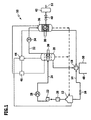
- FIG. 1 shows a schematic and simplified representation of an embodiment of a device according to the invention, which is designated as a whole by 10.
- the apparatus 10 comprises a fuel tank 12 in which a fuel, e.g. Kerosene, gasoline or diesel fuel, is stored.
- the fuel tank 12 is connected via a fuel line 14 with a controllable valve 16 to a heat engine 18.
- the heat engine 18 may in particular be a jet engine or an internal combustion engine.
- the apparatus 10 further comprises a thermal separator 20 to which fuel can be supplied from the fuel tank 12 by means of a pump 22.
- a filter 26 and a heat exchanger 28 are further interposed.
- the thermal separator 20 according to a variant of the device 10 not according to the invention comprises means for rectifying the fuel, i. in particular a rectification column with which a mixture of aliphatic and / or aromatic hydrocarbons can be separated into one or more lower-boiling fractions (top fraction) and one or more higher-boiling fractions (bottoms fraction).
- the thermal separator 20 comprises a device for the crystallization of the fuel.
- a device for the crystallization of the fuel By cooling a hydrocarbon mixture, one or more crystallizing fractions can be separated as a solid from the liquid residual fraction of the mixture by means of such a device.
- An institution for fractional crystallization of the fuel conveniently comprises a precooler and a main cooler.
- the thermal separation device 20 comprises one or more heating and / or cooling elements 30, with which heat can be added or removed to the fuel for carrying out the thermal separation process, depending on whether a rectification or a fractional crystallization is carried out.
- the thermal separator 20 is connected via a further supply line 32 and a heat exchanger 34 connected therebetween to a conversion device 36.
- the conversion device 36 according to the present exemplary embodiment of the device 10 according to the invention is a reactor for the catalytic dehydrogenation of one or more hydrocarbons in the target fraction separated from the fuel. By means of a heating element 38, an optimum reaction temperature for the dehydrogenation reaction can be set.
- the conversion device 36 is connected to a fuel cell system 42 via a pressure regulating valve 40.
- the fuel cell system 42 includes one or more fuel cell blocks that can be powered by the hydrogen generated in the conversion device 36 as fuel gas.
- the device 10 further comprises a measuring and control system for carrying out the method according to the invention, which is described in the FIG. 1 in the form of a measuring device 44 and a control device 46 is shown.
- a measuring device 44 various process parameters in the separator 20 and the conversion device 36 can be detected, such as the temperature and pressure of the fuel and the various fractions, the reaction temperature in the catalytic dehydrogenation, the hydrogen partial pressure, and temporal changes of these parameters.
- the level in the fuel tank 12 and optionally the composition of the fuel can be detected.
- the process control can be controlled by the control device 46.
- the inventive method works as follows:
- the fuel provided in the fuel tank 12 is supplied to the heat engine 18 via the fuel line 14 and the valve 16.
- both mechanical and thermal energy is generated (indicated by the arrows 48 and 50).
- the mechanical energy depending on the application of the device 10, e.g. is used for driving a motor vehicle or an aircraft, a part of the thermal energy generated by the heat engine 18 can be used in an efficient manner within the method according to the invention, in particular the thermal separator 20 via the heating element 30 and the conversion means 36 via the heating element 38th to supply with the necessary thermal energy.
- a lesser proportion of the fuel is employed by the fuel cell system 42 in the method of producing electrical energy in accordance with the present invention.
- a corresponding part of the fuel from the fuel tank 12 through the supply line 24 of the thermal separator 20 is supplied.
- the heat exchanger 28 serves to bring the fuel to a predetermined temperature even before being fed to the thermal separator 20, so that the thermal separation process can be carried out as reproducibly as possible.
- the fuel is accordingly preheated or pre-cooled by the heat exchanger 28.
- the fuel supplied to the thermal separator 20 by means of the heating element 30 heated and at least partially evaporated.
- Different fractions of the fuel ie in particular different hydrocarbons
- One or more lower boiling fractions optimized for the production of hydrogen over the fuel are separated as the target fraction.
- the rectification of the fuel by the thermal separator 20 may be carried out either under normal pressure or under reduced pressure.
- the thermal separation process comprises a fractional crystallization of the fuel.
- the fuel is thereby cooled by one or more cooling elements 30 so far that one or more components (i.e., especially hydrocarbons) crystallize due to their higher melting point compared to the other components.
- the fuel is first cooled in a pre-cooling unit (eg down to -40 ° C in the case of kerosene), and the pre-cooled fuel is then further cooled in a main cooling unit until crystallization (eg up to -90 ° C in the case of kerosene).
- the crystallized solid can be separated as a target fraction in a simple manner from the liquid residual fraction.
- the lower outside temperature for the cooling of the fuel by means of the cooling element or elements 30 can be utilized.
- the target fraction resulting from the thermal separation process is supplied to the conversion device 36 through the supply line 32. Since the target fraction may initially be in solid, liquid or gaseous form, depending on the nature of the thermal separation process, it is previously brought to a predetermined temperature by the heat exchanger 34 in order to to promote efficient and reproducible operation of the converter 36.
- the target fraction fed to the conversion device 36 is dehydrated or reformed by the action of a suitable catalyst, in particular a platinum, chromium, nickel, palladium or iron catalyst, to produce hydrogen.
- a suitable catalyst in particular a platinum, chromium, nickel, palladium or iron catalyst
- the target fraction contains one or more dehydrogenatable components, especially aliphatic hydrocarbons.
- the dehydrogenation reaction can be carried out at temperatures in the range of about 100 to 1500 ° C, wherein the required thermal energy is supplied through the heating element 38.
- the hydrogen produced by the conversion device 36 is separated from the remaining products of the dehydrogenation reaction and optionally further purification by means of a cleaning device (in the FIG. 1 not shown). It is fed via the pressure regulating valve 40 to the fuel cell system 42 for generating electrical energy (indicated by the arrow 52). As the oxidizing gas for the fuel cell system 42, atmospheric oxygen is used from the environment.
- Both the residual fraction of the fuel obtained in the thermal separation process and the products formed in the catalytic dehydrogenation can be fed directly from the thermal separator 20 or the converter 36 to the heat engine 18.
- a return into the fuel tank 12 is possible (shown by dashed arrows).
- these components have no significant effect on the operation of the heat engine 18, despite their changed composition compared to the fuel, since they account for only a very small proportion of the amount of fuel that is supplied to the heat engine as a whole.
- Kerosene (type Jet A-1), which is used as fuel for jet engines of aircraft.
- Kerosene comprises a complex mixture of a variety of aliphatic and aromatic hydrocarbons. It also contains various sulfur-containing compounds, typically 0.3% by weight of sulfides and 0.003% by weight of mercaptans, with the various sulfur compounds having boiling points in the range of about 35 to 240 ° C. In addition, even lower amount of disulfides and free sulfur are included. In this proportion, sulfur compounds act as a catalyst poison for the metal catalysts used in the catalytic dehydrogenation, so that kerosene as such can not be used for the production of hydrogen.
- diesel fuel was also investigated.
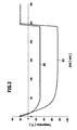
- Kerosene (Jet A-1) was subjected to a fractional crystallization, the kerosene in each case over a period of 5 hours initially in a pre-cooler to about -30 ° C and then in a main cooler to about -75 ° C was cooled.
- the exact temperature profile during the fractionated crystallization is shown in the diagram of FIG. 2 shown.
- the curve 60 indicates the temperature profile in the pre-cooler and the curve 62 indicates the temperature profile in the main cooler.
- the crystallized during the main cooling fraction of kerosene was separated from the still liquid fraction (residual fraction) and determines the proportion of sulfur-containing compounds in both fractions by gas chromatography.
- target fraction The crystallized during the main cooling fraction of kerosene (target fraction) was separated from the still liquid fraction (residual fraction) and determines the proportion of sulfur-containing compounds in both fractions by gas chromatography.
- the target fraction of kerosene obtained in this way by fractional crystallization can readily be used for catalytic dehydrogenation in the context of the process according to the invention because of the significantly reduced sulfur content.
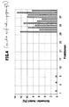
- composition of the target fraction and the residual fraction of kerosene after the fractional crystallization with respect to various types of hydrocarbons was also analyzed by gas chromatography.
- cycloalkanes and n-alkanes are present in the target fraction after fractional crystallization, while all other types of hydrocarbons (iso-alkanes, alkenes, aromatics and other hydrocarbons) are too remain over 90% in the residual fraction.
- Cycloalkanes naphthenes
- n-alkanes paraffins
- cycloalkanes typically being dehydrogenated to aromatics
- n-alkanes typically to alkenes.
- platinum or chromium catalysts can be used in particular.
- fractional crystallization can thus achieve a significant optimization of the composition of the hydrocarbon mixture with respect to the production of hydrogen.
Landscapes
- Engineering & Computer Science (AREA)
- Life Sciences & Earth Sciences (AREA)
- Sustainable Development (AREA)
- Sustainable Energy (AREA)
- Transportation (AREA)
- Mechanical Engineering (AREA)
- Power Engineering (AREA)
- Chemical & Material Sciences (AREA)
- Electrochemistry (AREA)
- General Chemical & Material Sciences (AREA)
- Combustion & Propulsion (AREA)
- Chemical Kinetics & Catalysis (AREA)
- Manufacturing & Machinery (AREA)
- Fuel Cell (AREA)
- Hydrogen, Water And Hydrids (AREA)
- Production Of Liquid Hydrocarbon Mixture For Refining Petroleum (AREA)
Claims (12)
- Dispositif (10) de production d'énergie mécanique et électrique à partir d'un combustible, comprenant.- un moteur thermique (18) fonctionnant au moyen du combustible ;- un dispositif de séparation thermique (20) au moyen duquel une fraction cible du combustible peut être séparée ;- un dispositif de conversion (36) au moyen duquel de l'hydrogène peut être produit à partir de la fraction cible ; et- un système de pile à combustible (42) fonctionnant au moyen de l'hydrogène comme gaz combustible,caractérisé en ce que le dispositif de séparation thermique (20) comporte un dispositif de cristallisation fractionnée du combustible.
- Dispositif (10) selon la revendication 1, dans lequel la fraction cible comporte un mélange d'hydrocarbures optimisé pour la production d'hydrogène par le dispositif de conversion (36) par rapport au combustible.
- Dispositif (10) selon la revendication 2, dans lequel la fraction cible présente une part d'hydrocarbures aliphatiques supérieure à celle du combustible.
- Dispositif (10) selon l'une quelconque des revendications précédentes, dans lequel la fraction cible présente une part de composés sulfureux inférieure à celle du combustible.
- Dispositif (10) selon l'une quelconque des revendications précédentes, dans lequel la fraction cible comporte une ou plusieurs fractions de combustible se recristallisant.
- Procédé de production d'énergie mécanique et électrique à partir d'un combustible, comprenant :- la mise à disposition d'un combustible pour le fonctionnement d'un moteur thermique ;- la séparation d'une fraction cible de combustible à l'aide d'un procédé de séparation thermique ;- la production d'hydrogène à partir de la fraction cible ; et- l'utilisation de l'hydrogène comme gaz combustible pour un système de pile à combustible, caractérisé en ce que le procédé de séparation thermique comporte une cristallisation fractionnée du combustible.
- Procédé selon la revendication 6, dans lequel la fraction cible comporte un mélange d'hydrocarbures optimisé pour la production d'hydrogène par rapport au combustible.
- Procédé selon la revendication 7, dans lequel la fraction cible présente une part d'hydrocarbures aliphatiques supérieure à celle du combustible.
- Procédé selon l'une quelconque des revendications 6 à 8, dans lequel la fraction cible présente une part de composés sulfureux inférieure à celle du combustible.
- Procédé selon l'une quelconque des revendications 6 à 9, dans lequel la fraction cible comporte une ou plusieurs fractions de combustible se recristallisant.
- Procédé selon l'une quelconque des revendications 6 à 10 pour le fonctionnement d'un véhicule terrestre, d'un navire ou d'un aéronef.
- Procédé selon la revendication 11, dans lequel la température ambiante du véhicule est utilisée pour la réalisation du procédé de séparation thermique.
Applications Claiming Priority (1)
| Application Number | Priority Date | Filing Date | Title |
|---|---|---|---|
| DE102008063507A DE102008063507A1 (de) | 2008-12-11 | 2008-12-11 | Vorrichtung und Verfahren zur Erzeugung von mechanischer und elektrischer Energie |
Publications (2)
| Publication Number | Publication Date |
|---|---|
| EP2197068A1 EP2197068A1 (fr) | 2010-06-16 |
| EP2197068B1 true EP2197068B1 (fr) | 2011-08-31 |
Family
ID=41718580
Family Applications (1)
| Application Number | Title | Priority Date | Filing Date |
|---|---|---|---|
| EP09176287A Active EP2197068B1 (fr) | 2008-12-11 | 2009-11-18 | Dispositif et procédé de production d'énergie mécanique et électrique |
Country Status (4)
| Country | Link |
|---|---|
| US (1) | US20100151292A1 (fr) |
| EP (1) | EP2197068B1 (fr) |
| AT (1) | ATE522944T1 (fr) |
| DE (1) | DE102008063507A1 (fr) |
Families Citing this family (5)
| Publication number | Priority date | Publication date | Assignee | Title |
|---|---|---|---|---|
| DE102010042678B4 (de) | 2010-10-20 | 2015-05-13 | Deutsches Zentrum für Luft- und Raumfahrt e.V. | Vorrichtung und Verfahren zur Erzeugung von mechanischer und elektrischer Energie aus einem Brennstoff |
| DE102014006430A1 (de) * | 2014-05-02 | 2015-11-05 | Hydrogenious Technologies Gmbh | Verfahren zur Energieversorgung insbesondere netzferner oder mobiler Verbraucher, Vorrichtung zum Durchführen eines solchen Verfahrens und darin verwendbares Stoffgemisch |
| CA3237910A1 (fr) | 2020-10-06 | 2022-04-14 | The Claire Technologies Corporation | Procede neutre en carbone de production d'electricite |
| WO2022203824A2 (fr) | 2021-03-02 | 2022-09-29 | The Claire Technologies Corporation | Système d'installation d'énergie neutre en carbone liquide |
| US11848467B2 (en) | 2020-10-14 | 2023-12-19 | Claire Technologies Corp. | Carbon-neutral process for generating electricity |
Family Cites Families (8)
| Publication number | Priority date | Publication date | Assignee | Title |
|---|---|---|---|---|
| DE19904820A1 (de) * | 1999-02-05 | 2000-08-10 | Stockhausen Chem Fab Gmbh | Verfahren und Vorrichtung zur Reinigung von Stoffen mittels Kristallisation |
| DE19911018C1 (de) * | 1999-03-12 | 2000-08-31 | Daimler Chrysler Ag | Hilfstriebwerk für ein Luftfahrzeug |
| DE19946606B4 (de) * | 1999-09-29 | 2013-07-04 | Robert Bosch Gmbh | Vorrichtung zum Bilden eines Kraftstoff-Luftgemischs für einen Verbrennungsmotor während einer Warmlaufphase |
| DE10336759A1 (de) * | 2002-11-29 | 2004-09-02 | Robert Bosch Gmbh | Verfahren und Vorrichtung zur Bereitstellung eines Kraftstoffs |
| GB2397540B (en) * | 2002-11-29 | 2005-01-19 | Bosch Gmbh Robert | Process and device for preparation of a fuel |
| DE102006013037B4 (de) * | 2006-03-20 | 2009-10-15 | Airbus Deutschland Gmbh | Vorrichtung, Verfahren und System zur Gewinnung von thermischer und/oder kinetischer sowie elektrischer Energie |
| US7691182B1 (en) * | 2006-12-12 | 2010-04-06 | University Of Central Florida Research Foundation, Inc. | Process for hydrogen production via integrated processing of landfill gas and biomass |
| US7862938B2 (en) * | 2007-02-05 | 2011-01-04 | Fuelcell Energy, Inc. | Integrated fuel cell and heat engine hybrid system for high efficiency power generation |
-
2008
- 2008-12-11 DE DE102008063507A patent/DE102008063507A1/de not_active Withdrawn
-
2009
- 2009-11-18 EP EP09176287A patent/EP2197068B1/fr active Active
- 2009-11-18 AT AT09176287T patent/ATE522944T1/de active
- 2009-12-03 US US12/630,730 patent/US20100151292A1/en not_active Abandoned
Also Published As
| Publication number | Publication date |
|---|---|
| US20100151292A1 (en) | 2010-06-17 |
| ATE522944T1 (de) | 2011-09-15 |
| DE102008063507A1 (de) | 2010-06-17 |
| EP2197068A1 (fr) | 2010-06-16 |
Similar Documents
| Publication | Publication Date | Title |
|---|---|---|
| EP1999815B1 (fr) | Dispositif, procédé et système de production d'énergie thermique et/ou cinétique et d'énergie électrique | |
| DE3490353C2 (de) | Herstellung von Brennstoffen, insbesondere Düsen- und Dieselbrennstoffen | |
| DE102009046790B9 (de) | Verfahren zur Erzeugung von Kohlenwasserstoffen, insbesondere Benzin, aus Synthesegas | |
| DE1770178B1 (de) | Verfahren zum katalytischen Reformieren einer Kohlenwasserstoffbeschickung | |
| EP2406349A2 (fr) | Procédé de préparation de composés aromatiques purs a partir de fractions d'hydrocarbure renfermant des composés aromatiques | |
| EP2197068A1 (fr) | Dispositif et procédé de production d'énergie mécanique et électrique | |
| DE202014011081U1 (de) | Erneuerbare Kohlenwasserstoff-Zusammensetzung | |
| DE2242330A1 (de) | Verfahren zur herstellung von kraftstoff fuer duesentriebwerke | |
| DE102005044926B3 (de) | Vorrichtung zur Erzeugung von Wasserstoffgas durch Dehydrogenierung von Kohlenwasserstoff-Brennstoffen | |
| EP4298187A1 (fr) | Système et procédé de production de combustibles synthétiques sans émission de dioxyde de carbone | |
| DE102010042678B4 (de) | Vorrichtung und Verfahren zur Erzeugung von mechanischer und elektrischer Energie aus einem Brennstoff | |
| DE2061945C3 (de) | Verfahren zur Herstellung von hochoctanigem Benzin | |
| DE2134155B2 (de) | Verfahren zur Herstellung von hoch oktamgem unverbleiten Benzin | |
| DE2620854A1 (de) | Verfahren zur trennung des aus einer kohlenwasserstoffumwandlungsanlage austretenden reaktionsproduktes | |
| DE102011015824A1 (de) | Luftfahrzeug-Brennstoffzellensystem, Luftfahrzeug und Verwendung eines synthetischen Brennstoffs | |
| DE2227740A1 (de) | Kohlenwasserstoffumwandlungsverfahren | |
| DE2246727A1 (de) | Verfahren zur herstellung leichter kohlenwasserstofffraktionen | |
| EP4653517A1 (fr) | Installation et procédé utilisant un reformeur autothermique pour la production de carburants synthétiques sans émission de dioxyde de carbone | |
| DE102018128534A1 (de) | Kraftstoffsystem für Triebwerke | |
| DE856492C (de) | Verfahren zur Herstellung von Hochleistungskraftstoffen aus Kohlenwasserstoffgemischen | |
| DE102021131890A1 (de) | Verfahren zur Herstellung von synthetischem Flugturbinenkraftstoff oder Kraftzusatzstoff | |
| DE1443074C (fr) | ||
| DE1042800B (de) | Verfahren zur Herstellung von fluessigen Kohlenwasserstoffgemischen mit hoher Octanzahl | |
| DE3218666C2 (de) | Verfahren zur gleichzeitigen Gewinnung von Ethylen und aromatischen Verbindungen aus durch hydrierende Verflüssigung von Kohle erhaltenen Produkten | |
| DE3040062A1 (de) | Neuer fluessigkraftstoff |
Legal Events
| Date | Code | Title | Description |
|---|---|---|---|
| PUAI | Public reference made under article 153(3) epc to a published international application that has entered the european phase |
Free format text: ORIGINAL CODE: 0009012 |
|
| AK | Designated contracting states |
Kind code of ref document: A1 Designated state(s): AT BE BG CH CY CZ DE DK EE ES FI FR GB GR HR HU IE IS IT LI LT LU LV MC MK MT NL NO PL PT RO SE SI SK SM TR |
|
| 17P | Request for examination filed |
Effective date: 20101210 |
|
| 17Q | First examination report despatched |
Effective date: 20110117 |
|
| GRAP | Despatch of communication of intention to grant a patent |
Free format text: ORIGINAL CODE: EPIDOSNIGR1 |
|
| RIC1 | Information provided on ipc code assigned before grant |
Ipc: B60K 6/32 20071001ALI20110131BHEP Ipc: H01M 8/06 20060101AFI20110131BHEP Ipc: H01M 8/00 20060101ALI20110131BHEP |
|
| GRAS | Grant fee paid |
Free format text: ORIGINAL CODE: EPIDOSNIGR3 |
|
| GRAA | (expected) grant |
Free format text: ORIGINAL CODE: 0009210 |
|
| AK | Designated contracting states |
Kind code of ref document: B1 Designated state(s): AT BE BG CH CY CZ DE DK EE ES FI FR GB GR HR HU IE IS IT LI LT LU LV MC MK MT NL NO PL PT RO SE SI SK SM TR |
|
| REG | Reference to a national code |
Ref country code: GB Ref legal event code: FG4D Free format text: NOT ENGLISH Ref country code: CH Ref legal event code: EP |
|
| REG | Reference to a national code |
Ref country code: IE Ref legal event code: FG4D Free format text: LANGUAGE OF EP DOCUMENT: GERMAN |
|
| REG | Reference to a national code |
Ref country code: DE Ref legal event code: R096 Ref document number: 502009001244 Country of ref document: DE Effective date: 20111027 |
|
| REG | Reference to a national code |
Ref country code: NL Ref legal event code: VDEP Effective date: 20110831 |
|
| LTIE | Lt: invalidation of european patent or patent extension |
Effective date: 20110831 |
|
| PG25 | Lapsed in a contracting state [announced via postgrant information from national office to epo] |
Ref country code: SE Free format text: LAPSE BECAUSE OF FAILURE TO SUBMIT A TRANSLATION OF THE DESCRIPTION OR TO PAY THE FEE WITHIN THE PRESCRIBED TIME-LIMIT Effective date: 20110831 Ref country code: NO Free format text: LAPSE BECAUSE OF FAILURE TO SUBMIT A TRANSLATION OF THE DESCRIPTION OR TO PAY THE FEE WITHIN THE PRESCRIBED TIME-LIMIT Effective date: 20111130 Ref country code: LT Free format text: LAPSE BECAUSE OF FAILURE TO SUBMIT A TRANSLATION OF THE DESCRIPTION OR TO PAY THE FEE WITHIN THE PRESCRIBED TIME-LIMIT Effective date: 20110831 Ref country code: NL Free format text: LAPSE BECAUSE OF FAILURE TO SUBMIT A TRANSLATION OF THE DESCRIPTION OR TO PAY THE FEE WITHIN THE PRESCRIBED TIME-LIMIT Effective date: 20110831 Ref country code: IS Free format text: LAPSE BECAUSE OF FAILURE TO SUBMIT A TRANSLATION OF THE DESCRIPTION OR TO PAY THE FEE WITHIN THE PRESCRIBED TIME-LIMIT Effective date: 20111231 Ref country code: FI Free format text: LAPSE BECAUSE OF FAILURE TO SUBMIT A TRANSLATION OF THE DESCRIPTION OR TO PAY THE FEE WITHIN THE PRESCRIBED TIME-LIMIT Effective date: 20110831 Ref country code: HR Free format text: LAPSE BECAUSE OF FAILURE TO SUBMIT A TRANSLATION OF THE DESCRIPTION OR TO PAY THE FEE WITHIN THE PRESCRIBED TIME-LIMIT Effective date: 20110831 |
|
| PG25 | Lapsed in a contracting state [announced via postgrant information from national office to epo] |
Ref country code: GR Free format text: LAPSE BECAUSE OF FAILURE TO SUBMIT A TRANSLATION OF THE DESCRIPTION OR TO PAY THE FEE WITHIN THE PRESCRIBED TIME-LIMIT Effective date: 20111201 Ref country code: LV Free format text: LAPSE BECAUSE OF FAILURE TO SUBMIT A TRANSLATION OF THE DESCRIPTION OR TO PAY THE FEE WITHIN THE PRESCRIBED TIME-LIMIT Effective date: 20110831 Ref country code: CY Free format text: LAPSE BECAUSE OF FAILURE TO SUBMIT A TRANSLATION OF THE DESCRIPTION OR TO PAY THE FEE WITHIN THE PRESCRIBED TIME-LIMIT Effective date: 20110831 Ref country code: SI Free format text: LAPSE BECAUSE OF FAILURE TO SUBMIT A TRANSLATION OF THE DESCRIPTION OR TO PAY THE FEE WITHIN THE PRESCRIBED TIME-LIMIT Effective date: 20110831 |
|
| REG | Reference to a national code |
Ref country code: IE Ref legal event code: FD4D |
|
| PG25 | Lapsed in a contracting state [announced via postgrant information from national office to epo] |
Ref country code: CZ Free format text: LAPSE BECAUSE OF FAILURE TO SUBMIT A TRANSLATION OF THE DESCRIPTION OR TO PAY THE FEE WITHIN THE PRESCRIBED TIME-LIMIT Effective date: 20110831 Ref country code: SK Free format text: LAPSE BECAUSE OF FAILURE TO SUBMIT A TRANSLATION OF THE DESCRIPTION OR TO PAY THE FEE WITHIN THE PRESCRIBED TIME-LIMIT Effective date: 20110831 Ref country code: IE Free format text: LAPSE BECAUSE OF FAILURE TO SUBMIT A TRANSLATION OF THE DESCRIPTION OR TO PAY THE FEE WITHIN THE PRESCRIBED TIME-LIMIT Effective date: 20110831 |
|
| BERE | Be: lapsed |
Owner name: DEUTSCHES ZENTRUM FUR LUFT- UND RAUMFAHRT E.V. Effective date: 20111130 |
|
| PG25 | Lapsed in a contracting state [announced via postgrant information from national office to epo] |
Ref country code: IT Free format text: LAPSE BECAUSE OF FAILURE TO SUBMIT A TRANSLATION OF THE DESCRIPTION OR TO PAY THE FEE WITHIN THE PRESCRIBED TIME-LIMIT Effective date: 20110831 Ref country code: PL Free format text: LAPSE BECAUSE OF FAILURE TO SUBMIT A TRANSLATION OF THE DESCRIPTION OR TO PAY THE FEE WITHIN THE PRESCRIBED TIME-LIMIT Effective date: 20110831 Ref country code: RO Free format text: LAPSE BECAUSE OF FAILURE TO SUBMIT A TRANSLATION OF THE DESCRIPTION OR TO PAY THE FEE WITHIN THE PRESCRIBED TIME-LIMIT Effective date: 20110831 Ref country code: EE Free format text: LAPSE BECAUSE OF FAILURE TO SUBMIT A TRANSLATION OF THE DESCRIPTION OR TO PAY THE FEE WITHIN THE PRESCRIBED TIME-LIMIT Effective date: 20110831 Ref country code: PT Free format text: LAPSE BECAUSE OF FAILURE TO SUBMIT A TRANSLATION OF THE DESCRIPTION OR TO PAY THE FEE WITHIN THE PRESCRIBED TIME-LIMIT Effective date: 20120102 |
|
| PG25 | Lapsed in a contracting state [announced via postgrant information from national office to epo] |
Ref country code: DK Free format text: LAPSE BECAUSE OF FAILURE TO SUBMIT A TRANSLATION OF THE DESCRIPTION OR TO PAY THE FEE WITHIN THE PRESCRIBED TIME-LIMIT Effective date: 20110831 Ref country code: MC Free format text: LAPSE BECAUSE OF NON-PAYMENT OF DUE FEES Effective date: 20111130 |
|
| PLBE | No opposition filed within time limit |
Free format text: ORIGINAL CODE: 0009261 |
|
| STAA | Information on the status of an ep patent application or granted ep patent |
Free format text: STATUS: NO OPPOSITION FILED WITHIN TIME LIMIT |
|
| 26N | No opposition filed |
Effective date: 20120601 |
|
| PG25 | Lapsed in a contracting state [announced via postgrant information from national office to epo] |
Ref country code: BE Free format text: LAPSE BECAUSE OF NON-PAYMENT OF DUE FEES Effective date: 20111130 |
|
| REG | Reference to a national code |
Ref country code: DE Ref legal event code: R097 Ref document number: 502009001244 Country of ref document: DE Effective date: 20120601 |
|
| PG25 | Lapsed in a contracting state [announced via postgrant information from national office to epo] |
Ref country code: MK Free format text: LAPSE BECAUSE OF FAILURE TO SUBMIT A TRANSLATION OF THE DESCRIPTION OR TO PAY THE FEE WITHIN THE PRESCRIBED TIME-LIMIT Effective date: 20110831 Ref country code: MT Free format text: LAPSE BECAUSE OF FAILURE TO SUBMIT A TRANSLATION OF THE DESCRIPTION OR TO PAY THE FEE WITHIN THE PRESCRIBED TIME-LIMIT Effective date: 20110831 |
|
| PG25 | Lapsed in a contracting state [announced via postgrant information from national office to epo] |
Ref country code: ES Free format text: LAPSE BECAUSE OF FAILURE TO SUBMIT A TRANSLATION OF THE DESCRIPTION OR TO PAY THE FEE WITHIN THE PRESCRIBED TIME-LIMIT Effective date: 20111211 Ref country code: SM Free format text: LAPSE BECAUSE OF FAILURE TO SUBMIT A TRANSLATION OF THE DESCRIPTION OR TO PAY THE FEE WITHIN THE PRESCRIBED TIME-LIMIT Effective date: 20110831 |
|
| PG25 | Lapsed in a contracting state [announced via postgrant information from national office to epo] |
Ref country code: LU Free format text: LAPSE BECAUSE OF NON-PAYMENT OF DUE FEES Effective date: 20111118 |
|
| PG25 | Lapsed in a contracting state [announced via postgrant information from national office to epo] |
Ref country code: BG Free format text: LAPSE BECAUSE OF FAILURE TO SUBMIT A TRANSLATION OF THE DESCRIPTION OR TO PAY THE FEE WITHIN THE PRESCRIBED TIME-LIMIT Effective date: 20111130 |
|
| PG25 | Lapsed in a contracting state [announced via postgrant information from national office to epo] |
Ref country code: TR Free format text: LAPSE BECAUSE OF FAILURE TO SUBMIT A TRANSLATION OF THE DESCRIPTION OR TO PAY THE FEE WITHIN THE PRESCRIBED TIME-LIMIT Effective date: 20110831 |
|
| PG25 | Lapsed in a contracting state [announced via postgrant information from national office to epo] |
Ref country code: HU Free format text: LAPSE BECAUSE OF FAILURE TO SUBMIT A TRANSLATION OF THE DESCRIPTION OR TO PAY THE FEE WITHIN THE PRESCRIBED TIME-LIMIT Effective date: 20110831 |
|
| REG | Reference to a national code |
Ref country code: CH Ref legal event code: PL |
|
| PG25 | Lapsed in a contracting state [announced via postgrant information from national office to epo] |
Ref country code: LI Free format text: LAPSE BECAUSE OF NON-PAYMENT OF DUE FEES Effective date: 20131130 Ref country code: CH Free format text: LAPSE BECAUSE OF NON-PAYMENT OF DUE FEES Effective date: 20131130 |
|
| REG | Reference to a national code |
Ref country code: DE Ref legal event code: R082 Ref document number: 502009001244 Country of ref document: DE Representative=s name: HOEGER, STELLRECHT & PARTNER PATENTANWAELTE MB, DE |
|
| REG | Reference to a national code |
Ref country code: FR Ref legal event code: PLFP Year of fee payment: 7 |
|
| REG | Reference to a national code |
Ref country code: AT Ref legal event code: MM01 Ref document number: 522944 Country of ref document: AT Kind code of ref document: T Effective date: 20141118 |
|
| PG25 | Lapsed in a contracting state [announced via postgrant information from national office to epo] |
Ref country code: AT Free format text: LAPSE BECAUSE OF NON-PAYMENT OF DUE FEES Effective date: 20141118 |
|
| REG | Reference to a national code |
Ref country code: FR Ref legal event code: PLFP Year of fee payment: 8 |
|
| REG | Reference to a national code |
Ref country code: FR Ref legal event code: PLFP Year of fee payment: 9 |
|
| REG | Reference to a national code |
Ref country code: FR Ref legal event code: PLFP Year of fee payment: 10 |
|
| REG | Reference to a national code |
Ref country code: DE Ref legal event code: R082 Ref document number: 502009001244 Country of ref document: DE Representative=s name: HOEGER, STELLRECHT & PARTNER PATENTANWAELTE MB, DE |
|
| PGFP | Annual fee paid to national office [announced via postgrant information from national office to epo] |
Ref country code: DE Payment date: 20241010 Year of fee payment: 16 |
|
| PGFP | Annual fee paid to national office [announced via postgrant information from national office to epo] |
Ref country code: GB Payment date: 20241010 Year of fee payment: 16 |
|
| PGFP | Annual fee paid to national office [announced via postgrant information from national office to epo] |
Ref country code: FR Payment date: 20241010 Year of fee payment: 16 |