EP2197092B1 - Procédé destiné au montage d'un résolveur et machine électrique - Google Patents
Procédé destiné au montage d'un résolveur et machine électrique Download PDFInfo
- Publication number
- EP2197092B1 EP2197092B1 EP08171368.7A EP08171368A EP2197092B1 EP 2197092 B1 EP2197092 B1 EP 2197092B1 EP 08171368 A EP08171368 A EP 08171368A EP 2197092 B1 EP2197092 B1 EP 2197092B1
- Authority
- EP
- European Patent Office
- Prior art keywords
- resolver
- rotor
- recess
- stator
- axially
- Prior art date
- Legal status (The legal status is an assumption and is not a legal conclusion. Google has not performed a legal analysis and makes no representation as to the accuracy of the status listed.)
- Ceased
Links
- 238000000034 method Methods 0.000 title claims description 18
- 238000013100 final test Methods 0.000 description 4
- 230000006835 compression Effects 0.000 description 3
- 238000007906 compression Methods 0.000 description 3
- 230000008878 coupling Effects 0.000 description 3
- 238000010168 coupling process Methods 0.000 description 3
- 238000005859 coupling reaction Methods 0.000 description 3
- 238000006243 chemical reaction Methods 0.000 description 1
- 238000006073 displacement reaction Methods 0.000 description 1
- 239000003550 marker Substances 0.000 description 1
Images


Classifications
-
- H—ELECTRICITY
- H02—GENERATION; CONVERSION OR DISTRIBUTION OF ELECTRIC POWER
- H02K—DYNAMO-ELECTRIC MACHINES
- H02K24/00—Machines adapted for the instantaneous transmission or reception of the angular displacement of rotating parts, e.g. synchro, selsyn
-
- H—ELECTRICITY
- H02—GENERATION; CONVERSION OR DISTRIBUTION OF ELECTRIC POWER
- H02K—DYNAMO-ELECTRIC MACHINES
- H02K11/00—Structural association of dynamo-electric machines with electric components or with devices for shielding, monitoring or protection
- H02K11/20—Structural association of dynamo-electric machines with electric components or with devices for shielding, monitoring or protection for measuring, monitoring, testing, protecting or switching
- H02K11/21—Devices for sensing speed or position, or actuated thereby
- H02K11/225—Detecting coils
Definitions
- the present invention relates to a method for mounting a resolver comprising a resolver and a resolver rotor on a shaft, in particular an electric machine. Moreover, the present invention relates to such an electric machine.
- An electric machine can be equipped with a resolver to determine the rotational speed or the rotational position of the shaft of the electric machine.
- the resolver is usually attached to a bearing plate of the electric machine and the resolver rotor to the shaft. It is important that the resolver rotor and thus the shaft has a defined rotational position relative to the resolver stator. To ensure this, usually in the final test of an electrical machine, the resolver is adjusted relative to the resolver rotor in that the resolver is rotated accordingly. However, this adjustment represents a relatively complex procedure in the final test.
- the object of the present invention is thus to simplify the adjustment of a resolver on an electrical machine.
- this object is achieved by a method for mounting a resolver, which has a resolver stator and a resolver rotor, on a shaft, by providing the resolver stator with at least one axially formed stator recess and providing the resolver rotor with at least one axially formed rotor recess and aligning the stator recess and the rotor recess in the rotational direction to each other by an assembly tool for mounting the resolver with a respective tool portion is inserted axially into the StatorausEnglishung and the rotor recess simultaneously.
- the invention provides an electric machine with a shaft and a resolver, which has a resolver stator and a resolver rotor, wherein the resolver stator has at least one stator recess and the resolver rotor at least one rotor recess, and the stator recess and the rotor recess are formed axially, so that Assembly tool for mounting the resolver to the shaft with a respective tool portion at the same time in the StatorausEnglishung and the rotor recess is axially plugged to exactly define the rotational position of both resolver components to each other.
- the assembly tool may comprise a hollow cylinder, on whose one end face two differently shaped pins project axially, which as the Tool sections are inserted into the StatorausEnglishung and the rotor recess for aligning. If the recesses are formed correspondingly negative to the pins, thereby a shape coding can be achieved, with which the rotational positions of resolver and resolver rotor can be clearly set to each other.
- the assembly tool may be a pressing tool which has a rod with an axially extending guide and a sleeve guided axially thereon, wherein the resolver rotor is guided axially with its rotor recess on the guide when pressed onto the shaft.
- a pressing tool which has a rod with an axially extending guide and a sleeve guided axially thereon, wherein the resolver rotor is guided axially with its rotor recess on the guide when pressed onto the shaft.
- the rod of the assembly tool can be designed so that it can be stuck form fit or rotationally axially on the shaft. As a result, an assembly with a clear assignment of the resolver rotor rotational position to the shaft rotational position is possible.
- the assembly tool can have at least one alignment rod which is parallel to the rod and which is inserted into the stator recess during alignment. About the rods, the assembly tool establishes a clear relationship between resolver and resolver rotor in terms of rotational position.
- the assembly tool has a radially oriented tool portion, the rotor recess and the Statoraus strictlyung are each frontally formed on the resolver rotor and the resolver, and the radially directed tool portion is inserted axially into the two recesses for aligning.
- This alignment of the resolver rotor and resolver is also possible if their end faces lie in a plane
- the assembly tool may have a form-fitting element, with which it is mounted against rotation on the shaft.
- the interlocking element may be formed so that it can be plugged onto the shaft only in a predetermined rotational position. This can be as in the above Example: Define a definite rotational position between the elements shaft, resolver stator and resolver rotor.
- a resolver according to the prior art explained in more detail. Accordingly, a resolver rotor 1 is screwed with a central screw 2 at the end of a shaft 3.
- the stator 4 of the resolver is fixedly connected to the housing 5 of the resolver and secured with screws 6 on the bearing plate of an electric machine.
- the Resolverstator 4 is rotatable at not fully tightened screws 6 on the electric machine.
- the stator 4 is rotated to the desired position, so that the resolver 4 is aligned with the resolver rotor 1. Subsequently, the screws 6 are finally tightened.
- this adjustment method is relatively expensive.
- a resolver is provided, which is based on the FIG. 2 to FIG. 4 will be explained in more detail below.
- the cross section of FIG. 2 shows a resolver in the delivery state.
- the resolver rotor 11 is supplied in pairs with the resolver stator 14.
- the resolver rotor 11 has an axial bore 113 through which a screw can be passed.
- a shoulder 117 is provided, on which a screw head rests.
- the resolver rotor 11 has two recesses 115 and 116 on its front side. These are two blind holes, which face each other at the circumference of 180 °.
- the recess 116 has a slightly larger diameter than the recess 115.
- the resolver stator 14 or its housing has two Statoraus strictlyened 141 and 142 frontally. These two Statoraus strictlyened 141, 142 are aligned axially with the rotor recesses 115, 116.
- the Statorausappelung 142 has the same diameter As the rotor recess 115 and the Statoraus Principleung 141 has the same diameter as the rotor recess 116th
- FIG. 3 shows an assembly tool 19. It essentially has a sleeve-shaped or hollow cylindrical body 190, on one end face of two pins 191 and 192 protrude axially.
- the pin 192 has a slightly larger diameter than the pin 191.
- the thicker pin 192 fits into the holes or recesses 116 and 141, but not in the recesses 115 and 142. This allows the mounting tool 19 only in a single position in the resolver be plugged. But this is only possible if the recesses 115 and 142 and the recesses 116 and 141 are exactly aligned axially. This in turn means that the resolver rotor 11 and the resolver stator 14 have a clearly defined rotational position relative to one another.
- FIG. 4 now shows the mounted state of the resolver.
- the resolver stator 14 is first centered on the bearing plate 10 of the electric machine.
- the resolver rotor 11 is centered on the motor shaft 13.
- the exact rotational position of the resolver rotor 11 relative to the resolver stator 14 is achieved in that the assembly tool 19 is inserted into the resolver.
- the thin pin 191 is inserted into the small recesses 115, 142 and the thick pin 192 into the large recesses 116, 141.
- the Resolverstator 14 is screwed with screws 16 (eg four on the circumference) to the bearing plate 10.
- the resolver rotor 11 is screwed with the central screw 12 to the end of the shaft 13.
- the entire resolver unit 11, 14 can thus be mounted in a specific rotational position on the shaft 13 and the relative rotational position of resolver rotor and resolver stator relative to one another is defined from the outset. A subsequent adjustment of these components can therefore be omitted.
- the assembly tool 19 is withdrawn axially from the resolver.
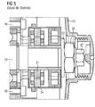
- FIG. 5 shows again a resolver with a known design.
- the resolver 21 is pressed onto a shaft 23 here.
- the resolver stator 24 or the resolver housing 25 is also fastened here with the aid of screws 26 on the end shield of the electrical machine.
- At the end of a hexagon 27 is incorporated in the shaft 23 to detect the exact rotational position of the shaft 23 and reach.
- the adjustment of the resolver or resolver rotor on the shaft 23 is also very troublesome here with the pressed Resolverrotor 21. Therefore, in a second embodiment, the resolver of FIG. 6 proposed.
- the Resolverrotor 31 shown there has an inner sleeve 311, with which it can be pressed onto a shaft. On the inside of this inner sleeve 311 extends in the axial direction a groove 312nd
- the resolver rotor 31 is surrounded by a resolver stator 34.
- a stator recess 341 can be seen on an end face of the resolver stator 34.
- This Statoraus originallyung 341 is rectangular in shape and has a certain axial extent.
- FIG. 7 a part of an assembly tool 39 is shown in perspective. It has a first rod 390, on the surface of which a raised guide 391 extends in the axial direction.
- the assembly tool 39 is a pressing tool and therefore has a compression sleeve 392, which is mounted axially displaceably on the first rod 390.
- the raised guide 391 slides into a groove 393 of the compression sleeve 392.
- a hexagon socket 394 is formed on the front side of the first rod 390.
- two further rods 395 and 396 are provided on the assembly tool 39 here. They have rectangular in the present example Cross section and are at the in FIG. 7 Not shown end connected to the first rod 390 so that they have a fixed position to each other.
- FIG. 8 to FIG. 11 Now the Aufpressvorgang the Resolverrotors 31 is shown on the end of a shaft 33.
- Resolver stator 34 is in FIG. 8 already attached with screws 36 on the bearing plate 30 of the electrical machine.
- a shoulder 331 can be seen, which constitutes a stop for the resolver rotor 31.
- a hexagon 332 is formed with a marking 333. This mark 333, for example, indicates a "center north pole" orientation of the rotor of the electric machine.
- the resolver stator 34 is to be aligned in the present example so that the radial direction, for example, the Statoraus Principleung 341 occupies a 90 ° angle with the radial direction of the marker 333.
- the two Statorausappel 341 and 342 lie in a horizontal plane, while the mark 333 points vertically upwards. In this state, the resolver is in the desired manner on the shaft 33 and the rotor of the electric machine aligned.
- FIG. 9 now shows a cross section through the part of the electrical machines with the resolver, wherein the central rod 390 of the mounting tool 39 on the end of the shaft 33, ie the hexagon 332 is placed.
- the resolver rotor 31 is axially displaceable on the first rod 390. Through the guide 391 in conjunction with its groove 312 it is secured against rotation.
- FIG. 10 It can be seen that the compression sleeve 392 of the mounting tool 39, the Resolverrotor 31 and its inner sleeve 311 pushes from the first rod 390 on the shaft 33 according to the arrows.
- FIG. 11 is the Aufpressvorgang finished. This can be seen from the fact that the sleeve 311 abuts the shaft shoulder 331 and is pushed completely by the first rod 390.
- the assembly tool 39 has caused with its hexagon socket 394 and its guide 391 that the resolver rotor 31 is aligned exactly with the shaft 33.
- the rigidly attached to the mounting tool further rods 395 and 396 cause the exact alignment of the resolver 34 in the direction of rotation relative to the resolver rotor 31 and the shaft 33. All three components (shaft 33, resolver rotor 31 and resolver 34) are thus adjusted to each other exactly, without that it requires a separate adjustment process after assembly.
- FIG. 12 shows a resolver in the delivery state. It has a resolver rotor 41 and a resolver stator 44. An end face 411 of the resolver rotor 41 is approximately flush with an end face 441 of the resolver stator 44. In the end face 411 two diametrically opposite Rotorausappelisme 412 and 413 are incorporated at the outer edge. Each of the two recesses 412 and 413 is associated with a StatorausEnglishung 441 and 442 opposite each other in the stator end face 440. It can be seen that the Statorausappelung 441 is slightly smaller than the Statorausappelung 442. The reason for this is again in the form of coding in order to achieve a clear positioning of the assembly tool can. The recesses 412, 413, 441 and 442 extend in the axial direction at a certain depth.
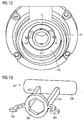
- FIG. 13 an assembly tool 49 is shown in perspective, which serves for the rotationally accurate plugging the resolver on a stub shaft.
- the assembly tool 49 has a handle 490. It is formed on two parallel rod-shaped webs 491 and 492, a ring 493 with a hexagon socket. Passage feet 494 and 495 are formed on two opposite sides of the ring 493. The right-hand foot 495 has a slightly larger foot area than the foot 494 for the purpose of shape coding.
- FIG. 14 is shown an oblique plan view of the front side of an electrical machine.
- the resolver 44 is fastened with screws 46 to the bearing plate 40 of the electric machine.
- Statorausappelisme 442 and 443 and the end of the shaft 43 with its frontal hexagon 432 and the mark 433 can be seen.
- FIG. 15 shows a section through the electric machine of FIG. 14 , wherein the resolver rotor 41 has already been slid almost completely onto the shaft 43 with the aid of the assembly tool 49.
- the resolver rotor 41 and the resolver stator 44 are not exactly opposite each other axially.
- the ring 493 is already pushed with its hexagon socket on the hexagon 432 of the shaft 43, so that the tool 49 assumes the desired rotational position relative to the shaft 43.
- the fitting feet 494 and 495 protrude into the rotor recesses 412 and 413, the resolver rotor 41 is also in the desired rotational position relative to the shaft 43.
- the fitting feet 494 and 495 of the mounting tool 49 also enter the stator recesses 441 and 442, whereby the resolver 44 is adjusted relative to the resolver rotor 41 and the shaft 43 with respect to its rotational position.
- This final assembly position is in a perspective view in FIG FIG. 16 shown. Since in the present example the resolver rotor 41 is not pressed onto the shaft 43 but is inserted only with little force, it is fastened on the shaft 43 with the aid of one or more setscrews 45. As a result, the resolver rotor 41 is secured against rotation and securely mounted against axial displacement on the shaft 43. After assembly, the assembly tool 49 is also withdrawn axially from the resolver or the shaft here.
Landscapes
- Engineering & Computer Science (AREA)
- Power Engineering (AREA)
- Microelectronics & Electronic Packaging (AREA)
- Transmission And Conversion Of Sensor Element Output (AREA)
Claims (14)
- Procédé de montage d'un résolveur, qui a un stator ( 4, 14, 24, 34, 44 ) de résolveur et un rotor ( 1, 11, 21, 31, 41 ) de résolveur sur un arbre ( 3, 13, 23, 33, 43 ),
caractérisé en ce que- on se procure le stator ( 4, 14, 24, 34, 44 ) de résolveur ayant au moins un évidement ( 141, 142, 341, 342, 441, 442 ) statorique constitué axialement et- on se procure le rotor ( 1, 11, 21, 31, 41 ) de résolveur ayant au moins un évidement ( 115, 116, 312, 412, 413 ) rotorique constitué axialement et- on oriente l'évidement ( 141, 142, 341, 342, 441, 442 ) statorique et l'évidement ( 115, 116, 312, 412, 413 ) rotorique dans le sens de rotation l'un par rapport à l'autre en emmanchant axialement un outil ( 19, 39, 49 ) de montage pour le montage du résolveur, ayant une partie ( 191, 192, 391, 395, 396, 494, 495) d'outil respectif en même temps dans l'évidement ( 141, 142, 341, 342, 441, 442 ) statorique et dans l'évidement ( 115, 116, 312, 412, 413 ) rotorique. - Procédé suivant la revendication 1, dans lequel l'outil ( 19, 39, 49 ) de montage comporte un cylindre ( 190 ) creux, à l'un des côtés frontaux duquel font saillie axialement deux broches ( 191, 192 ), qui sont emmanchées pour l'orientation en tant que parties de l'outil dans l'évidement ( 141, 142, 341, 342, 441, 442 ) statorique et dans l'évidement ( 115, 116, 312, 412, 413 ) rotorique.
- Procédé suivant la revendication 2, dans lequel on visse dans le cylindre ( 190 ) creux de l'outil ( 19, 39, 49 ) de montage une vis ( 12 ) ou un écrou pour la fixation du rotor ( 1, 11, 21, 31, 41 ) de résolveur dans/sur l'arbre ( 3, 13, 23, 33, 43 ).
- Procédé suivant la revendication 1, dans lequel l'outil ( 19, 39, 49 ) de montage est un outil d'application d'une pression, qui a une barre ( 390 ) ayant un guidage ( 391 ) s'étendant axialement et un manchon ( 392 ) qui y est guidé axialement et le rotor ( 1, 11, 21, 31, 41 ) du résolveur est guidé axialement sur le guidage ( 391 ) lors de l'application avec pression sur l'arbre ( 3, 13, 23, 33, 43 ) par son évidemment ( 115, 116, 312, 413 ) rotorique.
- Procédé suivant la revendication 4, dans lequel la barre ( 390 ) est emmanchée axialement à complémentarité de forme sur l'arbre ( 3, 13, 23, 33, 43 ).
- Procédé suivant la revendication 4 ou 5, caractérisé en ce que l'outil ( 19, 39, 49 ) de montage comporte au moins, parallèle à la barre ( 390 ), une barre ( 395, 396 ) d'orientation qui, lors de l'orientation, est emmanchée dans l'évidement ( 141, 142, 341, 342, 441, 442 ) statorique.
- Procédé suivant la revendication 1, dans lequel l'outil ( 19, 39, 49 ) de montage a une partie ( 494, 495 ) d'outil orientée radialement, l'évidement ( 115, 116, 312, 412, 413 ) rotorique et l'évidement ( 141, 142, 341, 342, 441, 442 ) statorique sont formés respectivement du côté frontal sur le rotor ( 1, 11, 21, 31, 41 ) du résolveur et sur le stator ( 4, 14, 24, 34, 44 ) du résolveur et la partie ( 494, 495 ) d'outil dirigée radialement est emmanchée pour l'orientation axialement dans les deux évidements.
- Procédé suivant la revendication 7, dans lequel l'outil ( 19, 39, 49 ) de montage comporte un élément ( 394, 493 ) à complémentarité de forme, par lequel il est emmanché sans possibilité de torsion sur l'arbre ( 3, 13, 23, 33, 43 ).
- Procédé suivant la revendication 8, dans lequel l'élément ( 394, 493 ) à complémentarité de forme ne peut être emmanché sur l'arbre ( 3, 13, 23, 33, 43 ) que dans une position en rotation prescrite.
- Procédé suivant l'une des revendications précédentes, dans lequel l'outil (19, 39, 49) de montage est, après la fixation du rotor ( 1, 11, 21, 31, 41 ) du résolveur sur l'arbre ( 3, 13, 23, 33, 43 ) et du stator ( 4, 14, 24, 34, 44 ) du résolveur sur un flasque ( 10, 30, 40 ) ou un carter de la machine électrique, retiré axialement du résolveur.
- Machine électrique comprenant- un arbre ( 3, 13, 23, 33, 43 ) et- un résolveur, qui a un stator ( 4, 14, 24, 34, 44 ) de résolveur et un rotor ( 1, 11, 21, 31, 41 ) de résolveur,
caractérisée en ce que- le stator ( 4, 14, 24, 34, 44 ) de résolveur a au moins un évidement ( 141, 142, 341, 342, 441, 442 ) statorique et le rotor ( 1, 11, 21, 31, 41 ) de résolveur a au moins un évidement ( 115, 116, 312, 412, 413 ) rotorique, et- l'évidement ( 141, 142, 341, 342, 441, 442 ) statorique et l'évidement (115, 116, 312, 412, 413) rotorique sont constitués axialement, de manière- à pouvoir emmancher axialement un outil ( 19, 39, 49 ) de montage, pour le montage du résolveur sur l'arbre ( 3, 13, 23, 33, 43 ) par une partie ( 191, 192, 391, 395, 396, 494, 495 ) d'outil respective en même temps dans l'évidement (141, 142, 341, 342, 441, 442) statorique et dans l'évidement (115, 116, 312, 412, 413) rotorique, pour fixer exactement l'un par rapport à l'autre la position en rotation des éléments du résolveur. - Machine électrique suivant la revendication 11, dans laquelle l'outil ( 19, 39, 49 ) de montage est emmanché sur le résolveur et a un cylindre ( 190 ) creux, de l'un des côtés frontaux duquel font saillie axialement deux broches ( 191, 192 ), qui sont, pour l'orientation, emmanchées comme partie d'outil dans l'évidement ( 141, 142, 341, 342, 441, 442 ) statorique et dans l'évidement ( 115, 116, 312, 412, 413 ) rotorique.
- Machine électrique suivant la revendication 11, dans laquelle l'outil ( 19, 39, 49 ) de montage est emmanché sur le résolveur et constitue un outil de presse, qui a une barre ( 390 ) ayant un guidage ( 391 ) s'étendant axialement et un manchon ( 392 ), qui y est guidé axialement, et le rotor ( 1, 11, 21, 31, 41 ) du résolveur est guidé axialement dans le guidage ( 391 ) par son évidement ( 115 ) rotorique.
- Machine électrique suivant la revendication 11, dans laquelle l'outil ( 19, 39, 49 ) de montage est emmanché sur le résolveur et a une partie ( 494, 495 ) d'outil dirigée radialement, l'évidement ( 115, 116, 312, 412, 413 ) rotorique et l'évidement (141, 142, 341, 342, 441, 442 ) statorique sont constitués respectivement du côté frontal du rotor ( 1, 11, 21, 31, 41 ) du résolveur et du stator ( 4, 14, 24, 34, 44 ) du résolveur et la partie ( 494, 495 ) d'outil dirigée radialement est emmanchée avec possibilité de retrait axial dans les deux évidements.
Priority Applications (1)
| Application Number | Priority Date | Filing Date | Title |
|---|---|---|---|
| EP08171368.7A EP2197092B1 (fr) | 2008-12-11 | 2008-12-11 | Procédé destiné au montage d'un résolveur et machine électrique |
Applications Claiming Priority (1)
| Application Number | Priority Date | Filing Date | Title |
|---|---|---|---|
| EP08171368.7A EP2197092B1 (fr) | 2008-12-11 | 2008-12-11 | Procédé destiné au montage d'un résolveur et machine électrique |
Publications (2)
| Publication Number | Publication Date |
|---|---|
| EP2197092A1 EP2197092A1 (fr) | 2010-06-16 |
| EP2197092B1 true EP2197092B1 (fr) | 2013-05-01 |
Family
ID=40793268
Family Applications (1)
| Application Number | Title | Priority Date | Filing Date |
|---|---|---|---|
| EP08171368.7A Ceased EP2197092B1 (fr) | 2008-12-11 | 2008-12-11 | Procédé destiné au montage d'un résolveur et machine électrique |
Country Status (1)
| Country | Link |
|---|---|
| EP (1) | EP2197092B1 (fr) |
Cited By (1)
| Publication number | Priority date | Publication date | Assignee | Title |
|---|---|---|---|---|
| DE102022103725A1 (de) | 2022-02-17 | 2023-08-17 | HELLA GmbH & Co. KGaA | Verfahren, System, Gehäuse und Leiterplatte zum Herstellen einer Drehwinkelsensoreinheit |
Families Citing this family (2)
| Publication number | Priority date | Publication date | Assignee | Title |
|---|---|---|---|---|
| WO2013174405A1 (fr) * | 2012-05-24 | 2013-11-28 | Baumüller Nürnberg GmbH | Machine électrique |
| CN118414767A (zh) | 2021-12-20 | 2024-07-30 | 索尤若驱动有限及两合公司 | 具有角度传感器的电机 |
Family Cites Families (4)
| Publication number | Priority date | Publication date | Assignee | Title |
|---|---|---|---|---|
| US4888509A (en) | 1988-02-05 | 1989-12-19 | Jaroslav Tomasek | Brushless servo motor construction and alignment |
| US5061868A (en) * | 1989-09-25 | 1991-10-29 | Nippon Densan Corporation | Spindle motor |
| DE102004056990B4 (de) * | 2004-11-25 | 2007-04-12 | Minebea Co., Ltd. | Elektrische Maschine, insbesondere bürstenloser Gleichstrommotor, und Verfahren zum Justieren einer Sensoreinheit in einer elektrischen Maschine |
| DE102007013049A1 (de) | 2007-03-19 | 2008-09-25 | Siemens Ag | Verfahren zum Montieren eines Winkelmessgeräts an einem elektrischen Motor |
-
2008
- 2008-12-11 EP EP08171368.7A patent/EP2197092B1/fr not_active Ceased
Cited By (1)
| Publication number | Priority date | Publication date | Assignee | Title |
|---|---|---|---|---|
| DE102022103725A1 (de) | 2022-02-17 | 2023-08-17 | HELLA GmbH & Co. KGaA | Verfahren, System, Gehäuse und Leiterplatte zum Herstellen einer Drehwinkelsensoreinheit |
Also Published As
| Publication number | Publication date |
|---|---|
| EP2197092A1 (fr) | 2010-06-16 |
Similar Documents
| Publication | Publication Date | Title |
|---|---|---|
| EP1821395B1 (fr) | Procédé destiné au réglage d'un couple de freinage et frein à hystérèse magnétique | |
| WO2007042473A1 (fr) | Rotor pour une machine electrique | |
| DE68907884T2 (de) | Zickzack-Nähmaschine. | |
| DE3300414C2 (fr) | ||
| DE102013113639B3 (de) | Befestigungsvorrichtung zum konzentrischen Befestigen einer Welle an eine Drehgeberwelle und Motorfeedback-System mit dieser Befestigung | |
| EP2197092B1 (fr) | Procédé destiné au montage d'un résolveur et machine électrique | |
| DE102010020355A1 (de) | Arretiervorrichtung für einen Triebstrang einer Windenergieanlage | |
| DE102012108031A1 (de) | Halter für eine Fügevorrichtung | |
| EP3053253B1 (fr) | Moteur électrique | |
| EP2495463B1 (fr) | Unité linéaire avec système tubulaire | |
| DE10021873B4 (de) | Elementsystem zum Aufbau von Halte- und/oder Messvorrichtungen | |
| DE3634118C2 (fr) | ||
| EP4043319A1 (fr) | Système de direction pour un véhicule automobile et procédé de montage d'un système de direction pour un véhicule automobile | |
| EP2999094A1 (fr) | Arbre en saillie pour un moteur électrique, moteur électrique doté d'un arbre en saillie, utilisation d'un arbre en saillie en tant qu'arbre de commande d'un encodeur et procédé de liaison d'un arbre en saillie à un arbre de commande d'un moteur électrique | |
| DE3307952A1 (de) | Elektromotor | |
| DE69810246T2 (de) | Befestigungsverfahren für ein Führungsglied auf einem Träger, nach diesem Verfahren hergestellte Führungseinrichtung und Markierungsgerät mit einer solchen Vorrichtung | |
| EP1749929B1 (fr) | Dispositif pour la fabrication ou le traitement d'une bande de matériau, en particulier une bande de papier ou de carton | |
| DE102014103138B4 (de) | Drehräummaschine | |
| DE2604874A1 (de) | Passystem fuer offset-rollen-rotationsdruckmaschinen | |
| DE102019113302B4 (de) | Werkzeug und Verfahren zum Herstellen von Umformteilen mit zwei durch Umformen hergestellten Funktionsflächen | |
| EP0801458A2 (fr) | Moteur électrique | |
| DE19600071C1 (de) | Seitenregistersystem für einen Plattenzylinder | |
| DE102005014808B4 (de) | Messeinrichtung | |
| EP2669050B1 (fr) | Outil, système et procédé de vissage de ressorts à boudin de compression sur une rondelle-ressort à boudin | |
| EP2424083A2 (fr) | Moteur électrique et son procédé de fabrication |
Legal Events
| Date | Code | Title | Description |
|---|---|---|---|
| PUAI | Public reference made under article 153(3) epc to a published international application that has entered the european phase |
Free format text: ORIGINAL CODE: 0009012 |
|
| 17P | Request for examination filed |
Effective date: 20090907 |
|
| AK | Designated contracting states |
Kind code of ref document: A1 Designated state(s): AT BE BG CH CY CZ DE DK EE ES FI FR GB GR HR HU IE IS IT LI LT LU LV MC MT NL NO PL PT RO SE SI SK TR |
|
| AX | Request for extension of the european patent |
Extension state: AL BA MK RS |
|
| AKX | Designation fees paid |
Designated state(s): DE |
|
| GRAP | Despatch of communication of intention to grant a patent |
Free format text: ORIGINAL CODE: EPIDOSNIGR1 |
|
| RAP1 | Party data changed (applicant data changed or rights of an application transferred) |
Owner name: SIEMENS AKTIENGESELLSCHAFT |
|
| GRAS | Grant fee paid |
Free format text: ORIGINAL CODE: EPIDOSNIGR3 |
|
| GRAA | (expected) grant |
Free format text: ORIGINAL CODE: 0009210 |
|
| AK | Designated contracting states |
Kind code of ref document: B1 Designated state(s): DE |
|
| REG | Reference to a national code |
Ref country code: DE Ref legal event code: R096 Ref document number: 502008009834 Country of ref document: DE Effective date: 20130704 |
|
| PLBE | No opposition filed within time limit |
Free format text: ORIGINAL CODE: 0009261 |
|
| STAA | Information on the status of an ep patent application or granted ep patent |
Free format text: STATUS: NO OPPOSITION FILED WITHIN TIME LIMIT |
|
| 26N | No opposition filed |
Effective date: 20140204 |
|
| REG | Reference to a national code |
Ref country code: DE Ref legal event code: R097 Ref document number: 502008009834 Country of ref document: DE Effective date: 20140204 |
|
| PGFP | Annual fee paid to national office [announced via postgrant information from national office to epo] |
Ref country code: DE Payment date: 20180219 Year of fee payment: 10 |
|
| REG | Reference to a national code |
Ref country code: DE Ref legal event code: R119 Ref document number: 502008009834 Country of ref document: DE |
|
| PG25 | Lapsed in a contracting state [announced via postgrant information from national office to epo] |
Ref country code: DE Free format text: LAPSE BECAUSE OF NON-PAYMENT OF DUE FEES Effective date: 20190702 |