EP2197099A2 - Betrieb von BLDC-Motoren - Google Patents
Betrieb von BLDC-Motoren Download PDFInfo
- Publication number
- EP2197099A2 EP2197099A2 EP09178494A EP09178494A EP2197099A2 EP 2197099 A2 EP2197099 A2 EP 2197099A2 EP 09178494 A EP09178494 A EP 09178494A EP 09178494 A EP09178494 A EP 09178494A EP 2197099 A2 EP2197099 A2 EP 2197099A2
- Authority
- EP
- European Patent Office
- Prior art keywords
- rotor position
- rotor
- motor
- commutation
- current
- Prior art date
- Legal status (The legal status is an assumption and is not a legal conclusion. Google has not performed a legal analysis and makes no representation as to the accuracy of the status listed.)
- Granted
Links
Images



Classifications
-
- H—ELECTRICITY
- H02—GENERATION; CONVERSION OR DISTRIBUTION OF ELECTRIC POWER
- H02P—CONTROL OR REGULATION OF ELECTRIC MOTORS, ELECTRIC GENERATORS OR DYNAMO-ELECTRIC CONVERTERS; CONTROLLING TRANSFORMERS, REACTORS OR CHOKE COILS
- H02P6/00—Arrangements for controlling synchronous motors or other dynamo-electric motors using electronic commutation dependent on the rotor position; Electronic commutators therefor
- H02P6/14—Electronic commutators
- H02P6/16—Circuit arrangements for detecting position
- H02P6/18—Circuit arrangements for detecting position without separate position detecting elements
- H02P6/185—Circuit arrangements for detecting position without separate position detecting elements using inductance sensing, e.g. pulse excitation
-
- H—ELECTRICITY
- H02—GENERATION; CONVERSION OR DISTRIBUTION OF ELECTRIC POWER
- H02P—CONTROL OR REGULATION OF ELECTRIC MOTORS, ELECTRIC GENERATORS OR DYNAMO-ELECTRIC CONVERTERS; CONTROLLING TRANSFORMERS, REACTORS OR CHOKE COILS
- H02P6/00—Arrangements for controlling synchronous motors or other dynamo-electric motors using electronic commutation dependent on the rotor position; Electronic commutators therefor
- H02P6/14—Electronic commutators
- H02P6/16—Circuit arrangements for detecting position
- H02P6/18—Circuit arrangements for detecting position without separate position detecting elements
- H02P6/183—Circuit arrangements for detecting position without separate position detecting elements using an injected high frequency signal
-
- H—ELECTRICITY
- H02—GENERATION; CONVERSION OR DISTRIBUTION OF ELECTRIC POWER
- H02P—CONTROL OR REGULATION OF ELECTRIC MOTORS, ELECTRIC GENERATORS OR DYNAMO-ELECTRIC CONVERTERS; CONTROLLING TRANSFORMERS, REACTORS OR CHOKE COILS
- H02P6/00—Arrangements for controlling synchronous motors or other dynamo-electric motors using electronic commutation dependent on the rotor position; Electronic commutators therefor
- H02P6/20—Arrangements for starting
- H02P6/22—Arrangements for starting in a selected direction of rotation
-
- H—ELECTRICITY
- H02—GENERATION; CONVERSION OR DISTRIBUTION OF ELECTRIC POWER
- H02P—CONTROL OR REGULATION OF ELECTRIC MOTORS, ELECTRIC GENERATORS OR DYNAMO-ELECTRIC CONVERTERS; CONTROLLING TRANSFORMERS, REACTORS OR CHOKE COILS
- H02P2203/00—Indexing scheme relating to controlling arrangements characterised by the means for detecting the position of the rotor
- H02P2203/03—Determination of the rotor position, e.g. initial rotor position, during standstill or low speed operation
Definitions
- the present invention relates to the operation of BLDC motors and in particular to the operation of BLDC motors at start up and at low to medium speeds.
- Driving of BLDC motors requires the knowledge of the rotor position relative to the stator coils. For a given rotor position, a current is forced through the stator coils in the appropriate direction to generate torque so as to turn the rotor in a desired direction. When the rotor has turned beyond a certain position, (the commutation point), the current direction needs to be varied (commutated) so that it is again in the appropriate direction to generate torque in the desired direction.
- the rotor position information can be determined using sensors, such as Hall-effect sensors or by appropriate means.
- the BEMF voltage induced in the stator coils by the rotor can be monitored to determine rotor position. These methods work best when the motor is operating at a steady speed above a particular threshold speed. Rotor position detection by these methods is thus less reliable at slow speeds and at start up or in conditions where the load on the motor varies over a wide range. For example, this may occur in motors used to drive oil pumps. Due to the strong dependency of oil viscosity on temperature, the required starting torque can vary by a factor 100 or more. Other examples include motors used in applications such as pumps, fans or actuators where operation at near-zero-speed is required.
- test pulses are imposed at intervals and the current change is measured differentially at the beginning and the end of each test pulse. These dI/dt values are then evaluated by a complex trigonomic function to calculate the current rotor position. Accordingly, it does not suffer from the drawback that the test pulse currents must have decayed before the next pulse can be initiated. However, the position is only measured when test pulses are inserted and insertion of test pulses also distorts the torque.
- a method of determining the rotor position in an electric motor comprising the steps of: superimposing one or more alternating signals on to the driving waveform so as to generate one or more oscillating currents in the stator coils; monitoring the variation in magnitude of the oscillating currents and thereby determining the rotor position.
- an electric motor operating in accordance with the method of the first aspect of the present invention.
- the present invention can be used to obtain rotor position estimation at start-up from stand-still and low to medium speeds.
- the method can be used in applications where a fast motor start is needed under unknown load conditions. It takes advantage of the impact that the rotors permanent magnets have on the stator coil inductances.
- the method is furthermore independent of the BEMF voltage.
- the present invention can be used to detect when the rotor has passed a certain position that coincides with the commutation instance.
- the method of the present invention can be combined with known methods for estimating an initial rotor position by way of applying test pulses and/or with known methods for estimating rotor position by way by evaluating BEMF voltage in an undriven coil.
- the motor may be a switched reluctance motor.
- the motor may be a brushless direct current (BLDC) motor.
- the BLDC motor may have any suitable number of stator coils.
- the driving waveform may be operated with a PWM duty cycle.
- the driving wave form may be operated with either a soft switching or hard switching PWM duty cycle.
- the alternating signals may be adapted such that they have a net torque effect in the same direction as the driving waveform.
- the amplitude of the oscillating currents may be monitored to determine the rotor position.
- the amplitude of the difference between the two oscillating currents is monitored to determine rotor position. Rotor position may be determined by reference to maxima or minima in the monitored currents or difference.
- the rotor position may be determined by reference to a plurality of sectors, each sector being defined by two commutation points.
- the amplitude of the difference between the two oscillating currents may reach a minima or maxima at the commutation points.
- a commutation command may be output.
- the driving waveform may be commutated.
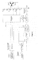
- a generalised BLDC motor 1 comprises a permanently magnetic rotor R and three driving phases U, V, W in the form of stator coils.
- the phases U, V, W are individually driven via buffers 5, 6, 7 respectively.
- the current flowing in each phase U, V, W is monitored by respective current sensors 8, 9, 10.
- the motor is driven by a driving waveform generated by driving signal generation unit 14.
- the driving signal comprises a torque generating waveform applied to one or more of the phases U, V, W in turn to generate a torque on the rotor, the one or more phases the waveform is applied to being commutated as the rotor position changes.
- one or more alternating signals are applied to one or more of the phases U, V, W.
- the one or more alternating signals generate oscillating currents in the stator coils U, V, W which are detected by current sensors 8, 9, 10.
- two alternating signals may be used, the alternating signals adapted such that superposition of the alternating signals cancels out the direct effect of the alternating signals on the torque generating waveform
- the amplitude of the oscillating currents is dependent upon both the resistance and inductance of the stator coils U, V, W.
- the resistance may be dependent upon temperature but is independent of rotor position whereas the inductance is dependent upon the rotor position.
- short term variations in the amplitude of the oscillating current can be assumed to be dependent upon the rotor position and thus by monitoring these variations, the rotor position can be determined.
- the alternating signals may be arranged such that for a specific motor, the ideal instant for driving waveform commutation coincides with the local maxima or minima of the oscillating current amplitude. Accordingly, the amplitude of the oscillating current may be monitored over time to determine the rotor position and an appropriate time of commutation. This method is reliable even at low operational speeds or with significant load variations.
- a synchronization unit 15 synchronizes the operation of the current processing and filtering unit 11 with the current measurement (sampling) instances with the driving signals.
- the maxima/minima detection unit 12 monitors the incoming signal with respect to time and detects functional extremes. For example, assume that for a specific motor, the ideal instance of commutation coincides with the local minima of the oscillating current amplitude. In this case the unit 12 would compare incoming samples with the previous input sample and signal a commutation command to the unit 13 when the current sample is larger than the previous sample.
- the position estimation unit 13 determines a sector of the motor within which the axis of the rotor lies and determines when the rotor axis passes from one sector to the next.
- the position estimation unit 13 outputs the current sector (rotor position) information and change of sector information to the driving signal generation unit 14 to enable commutation at the appropriate time.
- the position estimation unit 13 has an initialization input 17, which enables it to be switched on at motor start up.
- the driving signal generation unit 14 is also operable in response to signals received via the speed torque command input 16, to vary the magnitude PWM duty cycle or other characteristics of the torque generating waveform to vary the motor speed or the torque generated.
- the motor comprises three phases (stator coils) U, V, W.
- the schematic layout of the motor control circuitry as is shown in figure 5 will be described further below.
- the orientation of the rotor and the direction of possible signals or alternating signals will be defined with reference to figures 2a and 2b and table 1.
- the rotor position is defined by the orientation of its magnetic with respect to sectors R1, R2, R3, R4, R5, R6 with a fixed relation to the phases U, V, W.
- the rotor position determines which current should be applied in order to accomplish a particular rotation, the labelled directions Q1-Q6 indicating the direction in which the rotor will be urged to align by the corresponding current.
- the rotor is positioned within sector R2.
- current Q2 is applied.
- the rotor will try to align itself with the direction of Q2 and will thus move to sector R3.
- Table 1 shows the relation between the torque producing current and the rotor sector for clockwise rotation.
- Rotor Angle Rotor-axis section Torque Producing Current for clock wise rotation Alternating Current 1 Alternating Current 2 60...120 R1 Q1 Q6 ⁇ Q1 Q1 ⁇ Q2 120...180 R2 Q2 Q1 ⁇ Q2 Q2 ⁇ Q3 180...240 R3 Q3 Q2 ⁇ Q3 Q3 ⁇ Q4 240...300 R4 Q4 Q3 ⁇ Q4 Q4 ⁇ Q5 300...360 R5 Q5 Q4 ⁇ Q5 Q5 ⁇ Q6 0...60 R6 Q6 Q5 ⁇ Q6 Q6 ⁇ Q1
- figure 3a shows the torque producing signal applied to phases U, V, W with a soft switching PWM modulation to achieve current direction Q2.
- the ration of hi-time to lo-time of phase V is the torque producing PWM duty cycle.
- Figure 3b shows the equivalent torque generating signal for hard switching PWM duty cycle modulation. In both cases phase W is undriven.
- FIGS. 4a and 4b these illustrate the application of both the torque generating signal and the alternating signals of the present invention.
- the soft switching PWM Q2 signal is applied.
- the alternating signals to be applied are Q1 ⁇ Q2 and Q2 ⁇ Q3 that is Q1 in parallel with Q2 (+I_12) and Q3 in parallel with Q2 (+I_23).
- Q1 ⁇ Q2 is achieved from the start of the sequence to the point I_12(n) and Q2 ⁇ Q3 is achieved from the rising edge on phase W to I_23(n). The cycle then repeats.
- the BLDC motor is driven by six N-channel transistors, enabling each motor phase U, V, W to be connected to the supply voltage (V BAT ) or via a common shunt resistor Rshunt to ground (GND).
- the voltage over Rshunt is amplified and fed to an analogue-to-digital converter (ADC) with preceding sample and hold circuit (S&H).
- ADC start-of-conversion command (SOC) is provided by the Timer & Synchronization Unit. The timer and synchronization unit aligns the SOC with the driving signals so that the ADC can provide samples which are representative for the magnitude of the alternating currents to the sample unit.
- the PWM Modulation Module drives the 6 N-channel power transistors. It receives a PWM pattern from the PWM pattern unit and modulates that onto the clock input. It also provides a reference signal to the Timer and Synchronisation unit so that this unit can synchronize the current sampling instances.
- the PWM Pattern generation unit receives the current rotor position information (sector) and the torque producing PWM duty cycle command inputs. In response thereto the PWM pattern unit selects the appropriate PWM pattern in order to superimpose the torque generating signal and two alternating signals according to the present invention. The appropriate signals are selected from table 1, as was described previously.
- the amplitude of the oscillating currents generated by the alternating signals is compared to each other.
- the difference between the magnitude of the two oscillating currents reaches a local maximum at the commutation point. Since the difference between two oscillating currents is considered, the algorithm is robust against current variations, which might result from varying battery supply voltages or varying coil resistances due to temperature, for example.
- the sampling of the current by the ADC takes place at I_12(n) for the first current Q1 ⁇ Q2 and at time I_23(n) for the second current Q2 ⁇ Q3 for a given cycle n.
- the samples I_12(n) and 1_23(n) are stored as Sample 1 and Sample 2, respectively.
- 1_23(n) is available, they are subtracted from each other in the Subtraction Unit and the result is fed to a low pass filter.
- samples are taken at I_12(n+1) and I_23(n+1) and are processed in the same way as Sample 1 and Sample 2, respectively.
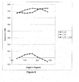
- Figure 6 shows measurements that were taken on a motor test stand for a 400W automotive BLDC motor with 4 pole pairs.
- the two currents I_12 and I_23 were measured by a 10-bit ADC converter via a 1mOhm shunt resistor and a current sense amplifier with gain 50. The two currents were sampled while the rotor was locked at a given angle.
- Figure 6 shows the values of I_12, I_23 and I_12 - I_23 vs. the rotor position.
- the difference I_12 - I_23 reaches a maximum at 180°, the commutation point. At this point, a commutation command can be generated.
- the low pass filter removes noise and provides samples to the Falling Edge Detection Unit.
- the Falling edge Detection unit is enabled by the Settling Detection Filter.
- the Settling Detection Filter enables the Falling Edge Detection Unit once a predetermined interval has occurred since a Commutation Command was given by the Falling Edge Detection Unit.
- the Settling Detection Filter may also monitor the measured currents to determine when a ringing disturbance on the motor currents caused by the application of a new PWM pattern (after each commutation command) has sufficiently decayed.
- figure 7 shows the output of the low pass filter, the Commutation Command generated by the Falling Edge Detection Unit and the ENABLE signal generated by the Settling Detection Filter for the example motor running at around 100rpm. It can be seen that in this implementation some hysteresis was built inside the Falling Edge Detection Unit in order to guarantee robust operation under noisy automotive environments.
- the method works for star and delta constructed motors and is independent on the number of coils per motor phase and on the number of poles of the rotors permanent magnet. Whilst the invention has been described with relation to BLDC motors, the skilled man will appreciate that it can also be applied to switched reluctance motors. The method has been explained above with relation to clockwise rotation. The skilled man will of course appreciate that the same techniques can be applied with suitable adjustment to anticlockwise rotation.
Landscapes
- Engineering & Computer Science (AREA)
- Power Engineering (AREA)
- Control Of Motors That Do Not Use Commutators (AREA)
Applications Claiming Priority (1)
| Application Number | Priority Date | Filing Date | Title |
|---|---|---|---|
| GBGB0822515.3A GB0822515D0 (en) | 2008-12-10 | 2008-12-10 | Operation of BLDC motors |
Publications (3)
| Publication Number | Publication Date |
|---|---|
| EP2197099A2 true EP2197099A2 (de) | 2010-06-16 |
| EP2197099A3 EP2197099A3 (de) | 2017-01-04 |
| EP2197099B1 EP2197099B1 (de) | 2023-08-30 |
Family
ID=40289795
Family Applications (1)
| Application Number | Title | Priority Date | Filing Date |
|---|---|---|---|
| EP09178494.2A Active EP2197099B1 (de) | 2008-12-10 | 2009-12-09 | Betrieb von elektrischen Motoren |
Country Status (3)
| Country | Link |
|---|---|
| US (1) | US8593098B2 (de) |
| EP (1) | EP2197099B1 (de) |
| GB (1) | GB0822515D0 (de) |
Cited By (1)
| Publication number | Priority date | Publication date | Assignee | Title |
|---|---|---|---|---|
| CN104641549B (zh) * | 2012-07-20 | 2017-03-29 | 博泽(维尔茨堡)汽车零部件有限公司 | 用于确定电子换向式多相直流马达的转子位置的方法 |
Families Citing this family (18)
| Publication number | Priority date | Publication date | Assignee | Title |
|---|---|---|---|---|
| GB0815672D0 (en) * | 2008-08-28 | 2008-10-08 | Melexis Nv | Improvements of accuracy of rotor position detection relating to the control of brushless dc motors |
| JP4858597B2 (ja) * | 2008-11-28 | 2012-01-18 | 株式会社デンソー | 回転機の制御装置及びその製造方法 |
| US8692398B2 (en) | 2012-03-30 | 2014-04-08 | Thermo King Corporation | Mobile environment-controlled unit having a magnetic sensor for a high-voltage alternating current bus |
| WO2013156052A1 (en) * | 2012-04-16 | 2013-10-24 | Abb Technology Ltd | A method for estimating motor parameter in a load commutated inverter arrangement, and a load commutated inverter arrangement therefor |
| CN103840725B (zh) * | 2012-11-26 | 2016-05-18 | 台达电子工业股份有限公司 | 永磁同步电机转子位置偏差测量装置及方法 |
| WO2014108746A1 (en) | 2013-01-09 | 2014-07-17 | Freescale Semiconductor, Inc. | Device for determining a position of a rotor of a polyphase electric motor |
| US9525371B2 (en) * | 2014-03-31 | 2016-12-20 | Stmicroelectronics S.R.L. | Apparatus for detecting the rotor position of an electric motor and related method |
| CN104129314B (zh) * | 2014-07-18 | 2017-03-01 | 成都宇能通能源开发有限公司 | 一种采用开关磁阻电机作为功率变压器的动力系统 |
| KR101869665B1 (ko) * | 2014-08-19 | 2018-07-20 | 광동 웰링 모터 매뉴팩처링 컴퍼니, 리미티드 | 공조기 및 실외 팬 작동 제어 방법 및 시스템 |
| CN104467338B (zh) * | 2014-12-31 | 2018-04-03 | 湖南开启时代电子信息技术有限公司 | 一种无转子位置传感器的开关磁阻电机 |
| GB2542633A (en) * | 2015-09-28 | 2017-03-29 | Melexis Technologies Nv | Method of starting a three-phase BLDC motor and motor driver using same |
| EP3461299B1 (de) * | 2016-06-16 | 2020-11-11 | Allegro MicroSystems, LLC | Bestimmung einer motorposition |
| US10116243B2 (en) | 2016-06-16 | 2018-10-30 | Allegro Microsystems, Llc | Determining motor position with complementary drive and detect and slight move |
| US10181810B2 (en) | 2016-06-16 | 2019-01-15 | Allegro Microsystems, Llc | Determining motor position with complementary driving and detection and current injection |
| US11277086B2 (en) | 2017-09-22 | 2022-03-15 | Janislav SEGA | Radially symmetric three-phase optimized power control PCB layout |
| US10897217B2 (en) * | 2018-08-21 | 2021-01-19 | Caterpillar Inc. | Switched reluctance motor control system |
| US11362607B1 (en) * | 2021-02-18 | 2022-06-14 | Global Mixed-Mode Technology Inc. | Motor unit |
| WO2022226579A1 (en) * | 2021-04-27 | 2022-11-03 | Janislav Sega | Electronic commutation of a sensorless brushless motor |
Family Cites Families (51)
| Publication number | Priority date | Publication date | Assignee | Title |
|---|---|---|---|---|
| EP0210047A3 (de) * | 1985-07-16 | 1987-09-30 | Maghemite Inc. | Motorregler und sein Betriebsablauf |
| US4772839A (en) * | 1987-10-27 | 1988-09-20 | General Electric Company | Rotor position estimator for switched reluctance motor |
| US4928043A (en) * | 1988-11-14 | 1990-05-22 | Synektron Corporation | Back EMF sampling circuit for phase locked loop motor control |
| US5001405A (en) * | 1989-09-27 | 1991-03-19 | Seagate Technology, Inc. | Position detection for a brushless DC motor |
| US4992710A (en) * | 1989-09-27 | 1991-02-12 | Seagate Technology, Inc. | Position detection for a brushless DC motor with sample time optimization |
| AU630820B2 (en) * | 1990-07-04 | 1992-11-05 | Matsushita Electric Industrial Co., Ltd. | Brushless dc motor |
| US5097190A (en) * | 1991-02-11 | 1992-03-17 | General Electric Company | Rotor position estimator for a switched reluctance machine |
| EP0579694B1 (de) * | 1991-04-11 | 1995-12-13 | Elin Energieanwendung Gesellschaft M.B.H. | Verfahren und schaltungsanordnungen zur bestimmung maschinenbezogener elektromagnetischer und mechanischer zustandsgrössen an über umrichter gespeisten elektrodydynamischen drehfeldmaschinen |
| US5134349A (en) * | 1991-05-28 | 1992-07-28 | Kruse David L | Two-phase brushless dc motor controller |
| US5191270A (en) * | 1991-06-07 | 1993-03-02 | Sgs-Thomson Microelectronics, Inc. | Method for starting a motor |
| US5517095A (en) * | 1991-10-03 | 1996-05-14 | Sgs-Thomson Microelectronics, Inc. | Method and apparatus for operating polyphase DC motors using a PWM chopping signal in zero crossing determination |
| US5191269A (en) * | 1991-10-10 | 1993-03-02 | Sgs-Thomson Microelectronics, Inc. | Brushless direct current motor with minimized current ripple and method |
| US5384527A (en) * | 1993-05-12 | 1995-01-24 | Sundstrand Corporation | Rotor position detector with back EMF voltage estimation |
| US5446359A (en) * | 1993-12-29 | 1995-08-29 | Emerson Electric Co. | Current decay control in switched reluctance motor |
| US5473240A (en) * | 1993-12-30 | 1995-12-05 | Whirlpool Corporation | Motor control using third harmonic stator voltage signal |
| US5525874A (en) * | 1995-01-30 | 1996-06-11 | Delco Electronics Corp. | Digital slope compensation in a current controller |
| WO1997027667A1 (en) * | 1996-01-24 | 1997-07-31 | Philips Electronics N.V. | Arrangement for supplying drive signals to a plurality of windings of a multi-phase d.c. motor, drive system and disk drive |
| KR100233124B1 (ko) * | 1996-04-04 | 1999-12-01 | 윤종용 | 팩시밀리의 원고독취부 롤러 장치 |
| FR2747521B1 (fr) * | 1996-04-12 | 1998-06-26 | Sgs Thomson Microelectronics | Commande d'un moteur sans collecteur |
| US6163120A (en) * | 1996-12-17 | 2000-12-19 | Stmicroelectronics, Inc. | Simple back emf reconstruction in pulse width modulation (PWM) mode |
| DK0972332T3 (da) | 1997-02-05 | 2004-07-26 | Fisher & Paykel Appliances Ltd | Styring af börstelös jævnströmsmotor |
| EP0892489B1 (de) | 1997-07-15 | 2005-10-05 | STMicroelectronics S.r.l. | Messung der momentanen Stellung des Rotors eines, im tripolaren Modus getriebenen bürstenlosen Gleichstrommotors |
| US6107772A (en) * | 1997-09-26 | 2000-08-22 | Dana Corporation | Sensorless switched reluctance motor control |
| US6072289A (en) * | 1998-04-28 | 2000-06-06 | Texas Instruments Incorporated | System and method for controlling high side slew rate in a spindle motor driver |
| US20010048278A1 (en) * | 1999-02-04 | 2001-12-06 | Glen C. Young | Cross coupled motor gate drive |
| US6081091A (en) * | 1999-03-08 | 2000-06-27 | Motorola, Inc. | Motor controller, integrated circuit, and method of controlling a motor |
| US6124689A (en) * | 1999-03-26 | 2000-09-26 | Quantum Corporation | Trapezoidal spindle motor driver |
| US6011368A (en) * | 1999-03-30 | 2000-01-04 | Dana Corporation | Sensorless detection of a locked rotor in a switched reluctance motor |
| US6023141A (en) * | 1999-05-13 | 2000-02-08 | Motorola, Inc. | Method and apparatus for electronically commutating an electric motor |
| US7138776B1 (en) * | 1999-07-08 | 2006-11-21 | Heartware, Inc. | Method and apparatus for controlling brushless DC motors in implantable medical devices |
| US6462495B1 (en) * | 2000-04-25 | 2002-10-08 | Infineon Technologies Ag | Controlling a brushless DC motor |
| JP3979561B2 (ja) * | 2000-08-30 | 2007-09-19 | 株式会社日立製作所 | 交流電動機の駆動システム |
| EP1198059A3 (de) * | 2000-10-11 | 2004-03-17 | Matsushita Electric Industrial Co., Ltd. | Verfahren und Vorrichtung für eine positionssensorlose Motorregelung |
| US6795268B1 (en) * | 2000-10-31 | 2004-09-21 | Western Digital Technologies, Inc. | Disk drive employing seek time vcm ir voltage calibration for velocity control of an actuator arm |
| DE10162380A1 (de) * | 2001-12-19 | 2003-07-03 | Bosch Gmbh Robert | Verfahren zum Starten eines bürstenlosen Gleichstrommotors |
| ITMI20012835A1 (it) * | 2001-12-28 | 2003-06-28 | Abb Service Srl | Procedimento per la determinazione della posizione del rotore di una macchina sincrona a corrente alternata a magneti permanenti |
| DE10229319A1 (de) * | 2002-06-29 | 2004-01-29 | Braun Gmbh | Verfahren zum Steuern eines oszillierenden Elektormotors eines elektrischen Kleingeräts |
| US6828753B2 (en) * | 2002-08-26 | 2004-12-07 | International Rectifier Corporation | Input filter for A.C. motor phase current sensing |
| GB0220401D0 (en) * | 2002-09-03 | 2002-10-09 | Trw Ltd | Motor drive control |
| US6763622B2 (en) * | 2002-10-10 | 2004-07-20 | General Motors Corporation | Amplitude detection method and apparatus for high frequency impedance tracking sensorless algorithm |
| JP3693173B2 (ja) * | 2002-10-16 | 2005-09-07 | 日本サーボ株式会社 | 単相ブラシレスdcモータ |
| JP2004343862A (ja) | 2003-05-14 | 2004-12-02 | Matsushita Electric Ind Co Ltd | モータ制御装置 |
| CN100364225C (zh) * | 2003-06-30 | 2008-01-23 | 松下电器产业株式会社 | 无传感器电机驱动装置及其驱动方法 |
| US6995530B2 (en) * | 2004-04-22 | 2006-02-07 | International Business Machines Corporation | System, method, and an article of manufacture for starting a brushless direct current motor |
| ITTO20040399A1 (it) * | 2004-06-16 | 2004-09-16 | Univ Catania | Sistema e metodo di controllo per azionamenti elettrici con motori in corrente alternata. |
| JP4513536B2 (ja) * | 2004-12-06 | 2010-07-28 | 株式会社豊田自動織機 | インバータ装置 |
| US7166980B1 (en) * | 2005-02-23 | 2007-01-23 | Legrand Richard Mark | Methods and apparatus for monitoring a brushed permanent magnet motor using back-emf measurements |
| US7141949B2 (en) * | 2005-03-07 | 2006-11-28 | Fisher & Paykel Appliances Limited | Low noise back EMF sensing brushless DC motor |
| JP4425193B2 (ja) * | 2005-08-16 | 2010-03-03 | 三洋電機株式会社 | モータの位置センサレス制御装置 |
| US8030867B1 (en) * | 2006-07-29 | 2011-10-04 | Ixys Ch Gmbh | Sample and hold time stamp for sensing zero crossing of back electromotive force in 3-phase brushless DC motors |
| JP4492732B2 (ja) * | 2008-05-13 | 2010-06-30 | 株式会社デンソー | モータ駆動装置、及び駆動装置状態判定方法 |
-
2008
- 2008-12-10 GB GBGB0822515.3A patent/GB0822515D0/en active Pending
-
2009
- 2009-12-09 EP EP09178494.2A patent/EP2197099B1/de active Active
- 2009-12-10 US US12/634,991 patent/US8593098B2/en active Active
Non-Patent Citations (1)
| Title |
|---|
| None * |
Cited By (1)
| Publication number | Priority date | Publication date | Assignee | Title |
|---|---|---|---|---|
| CN104641549B (zh) * | 2012-07-20 | 2017-03-29 | 博泽(维尔茨堡)汽车零部件有限公司 | 用于确定电子换向式多相直流马达的转子位置的方法 |
Also Published As
| Publication number | Publication date |
|---|---|
| US20100141192A1 (en) | 2010-06-10 |
| EP2197099B1 (de) | 2023-08-30 |
| GB0822515D0 (en) | 2009-01-14 |
| EP2197099A3 (de) | 2017-01-04 |
| US8593098B2 (en) | 2013-11-26 |
Similar Documents
| Publication | Publication Date | Title |
|---|---|---|
| US8593098B2 (en) | Operation of BLDC motors | |
| CN102577086B (zh) | 无传感器无刷直流马达中用于减少零交叉粒度的可变脉宽调制 | |
| US8040095B2 (en) | Synchronization of sequential phase switchings in driving stator windings of a multiphase sensorless brushless motor at sub BEMF-detectability speeds | |
| US11050370B2 (en) | Method for detecting magnetic field location in electric motor | |
| CN101938239A (zh) | 用于启动无刷无传感器dc电机的方法 | |
| US10171018B2 (en) | Method and electronic circuit for stall detection | |
| US7893649B2 (en) | Method and circuit arrangement for determining the rotor position of an EC motor in the standstill state | |
| US11201574B2 (en) | Method for detecting magnetic field location in electric motor | |
| TW200522474A (en) | Brushless motor without sensor | |
| CA2727125C (en) | Control of brushless motor | |
| US9667184B2 (en) | Device for determining a position of a rotor of a polyphase electric motor | |
| KR100189122B1 (ko) | 센서리스(sensorless) bldc 모터 제어방법 | |
| KR20180067029A (ko) | 진상각 제어기 | |
| US20160294310A1 (en) | Tri-stating brushless dc motor phase for direct detection of back emf zero cross | |
| US11424700B2 (en) | Hall element sensing circuit | |
| US11894795B2 (en) | Inductance-based, high-torque start up of electric motor | |
| US10804824B2 (en) | Method and circuit arrangement for determining the position of a rotor in an electric motor | |
| US9991827B1 (en) | Methods and apparatus for automatic lead angle adjustment using fly-back voltage for brushless DC control | |
| US7514888B2 (en) | Method and system for sensorless brushless DC motor control with predictive switch timing | |
| JP2014087113A (ja) | モータ駆動装置 | |
| JP2022186058A (ja) | センサレスモータの回転子位置検出方法及びセンサレスモータ駆動方法 | |
| JP2006121798A (ja) | モータ駆動装置 | |
| KR20000050368A (ko) | 브러쉬리스 직류 모터의 센서리스 모드전환장치 | |
| EP2503684B1 (de) | Steuerung eines bürstenlosen Motors | |
| KR20000042085A (ko) | 홀 소자의 직류 오프셋을 조절하는 비엘디시 모터 구동회로 및그를 갖는 비엘디시 모터 |
Legal Events
| Date | Code | Title | Description |
|---|---|---|---|
| PUAI | Public reference made under article 153(3) epc to a published international application that has entered the european phase |
Free format text: ORIGINAL CODE: 0009012 |
|
| AK | Designated contracting states |
Kind code of ref document: A2 Designated state(s): AT BE BG CH CY CZ DE DK EE ES FI FR GB GR HR HU IE IS IT LI LT LU LV MC MK MT NL NO PL PT RO SE SI SK SM TR |
|
| AX | Request for extension of the european patent |
Extension state: AL BA RS |
|
| RAP1 | Party data changed (applicant data changed or rights of an application transferred) |
Owner name: MELEXIS TECHNOLOGIES NV |
|
| PUAL | Search report despatched |
Free format text: ORIGINAL CODE: 0009013 |
|
| AK | Designated contracting states |
Kind code of ref document: A3 Designated state(s): AT BE BG CH CY CZ DE DK EE ES FI FR GB GR HR HU IE IS IT LI LT LU LV MC MK MT NL NO PL PT RO SE SI SK SM TR |
|
| AX | Request for extension of the european patent |
Extension state: AL BA RS |
|
| RIC1 | Information provided on ipc code assigned before grant |
Ipc: H02P 6/18 20160101AFI20161125BHEP Ipc: H02P 6/22 20060101ALI20161125BHEP |
|
| STAA | Information on the status of an ep patent application or granted ep patent |
Free format text: STATUS: REQUEST FOR EXAMINATION WAS MADE |
|
| 17P | Request for examination filed |
Effective date: 20170703 |
|
| RBV | Designated contracting states (corrected) |
Designated state(s): AT BE BG CH CY CZ DE DK EE ES FI FR GB GR HR HU IE IS IT LI LT LU LV MC MK MT NL NO PL PT RO SE SI SK SM TR |
|
| STAA | Information on the status of an ep patent application or granted ep patent |
Free format text: STATUS: EXAMINATION IS IN PROGRESS |
|
| 17Q | First examination report despatched |
Effective date: 20200217 |
|
| REG | Reference to a national code |
Ref country code: DE Ref legal event code: R079 Free format text: PREVIOUS MAIN CLASS: H02P0001160000 Ipc: H02P0006185000 Ref country code: DE Ref legal event code: R079 Ref document number: 602009064978 Country of ref document: DE Free format text: PREVIOUS MAIN CLASS: H02P0001160000 Ipc: H02P0006185000 |
|
| GRAP | Despatch of communication of intention to grant a patent |
Free format text: ORIGINAL CODE: EPIDOSNIGR1 |
|
| RIC1 | Information provided on ipc code assigned before grant |
Ipc: H02P 6/22 20060101ALI20230309BHEP Ipc: H02P 6/18 20060101ALI20230309BHEP Ipc: H02P 6/185 20160101AFI20230309BHEP |
|
| STAA | Information on the status of an ep patent application or granted ep patent |
Free format text: STATUS: GRANT OF PATENT IS INTENDED |
|
| INTG | Intention to grant announced |
Effective date: 20230413 |
|
| GRAS | Grant fee paid |
Free format text: ORIGINAL CODE: EPIDOSNIGR3 |
|
| GRAA | (expected) grant |
Free format text: ORIGINAL CODE: 0009210 |
|
| STAA | Information on the status of an ep patent application or granted ep patent |
Free format text: STATUS: THE PATENT HAS BEEN GRANTED |
|
| AK | Designated contracting states |
Kind code of ref document: B1 Designated state(s): AT BE BG CH CY CZ DE DK EE ES FI FR GB GR HR HU IE IS IT LI LT LU LV MC MK MT NL NO PL PT RO SE SI SK SM TR |
|
| REG | Reference to a national code |
Ref country code: GB Ref legal event code: FG4D |
|
| REG | Reference to a national code |
Ref country code: CH Ref legal event code: EP |
|
| REG | Reference to a national code |
Ref country code: DE Ref legal event code: R096 Ref document number: 602009064978 Country of ref document: DE |
|
| REG | Reference to a national code |
Ref country code: IE Ref legal event code: FG4D |
|
| P01 | Opt-out of the competence of the unified patent court (upc) registered |
Effective date: 20231109 |
|
| REG | Reference to a national code |
Ref country code: LT Ref legal event code: MG9D |
|
| REG | Reference to a national code |
Ref country code: NL Ref legal event code: MP Effective date: 20230830 |
|
| REG | Reference to a national code |
Ref country code: AT Ref legal event code: MK05 Ref document number: 1606714 Country of ref document: AT Kind code of ref document: T Effective date: 20230830 |
|
| PG25 | Lapsed in a contracting state [announced via postgrant information from national office to epo] |
Ref country code: GR Free format text: LAPSE BECAUSE OF FAILURE TO SUBMIT A TRANSLATION OF THE DESCRIPTION OR TO PAY THE FEE WITHIN THE PRESCRIBED TIME-LIMIT Effective date: 20231201 |
|
| PG25 | Lapsed in a contracting state [announced via postgrant information from national office to epo] |
Ref country code: IS Free format text: LAPSE BECAUSE OF FAILURE TO SUBMIT A TRANSLATION OF THE DESCRIPTION OR TO PAY THE FEE WITHIN THE PRESCRIBED TIME-LIMIT Effective date: 20231230 |
|
| PG25 | Lapsed in a contracting state [announced via postgrant information from national office to epo] |
Ref country code: SE Free format text: LAPSE BECAUSE OF FAILURE TO SUBMIT A TRANSLATION OF THE DESCRIPTION OR TO PAY THE FEE WITHIN THE PRESCRIBED TIME-LIMIT Effective date: 20230830 Ref country code: NO Free format text: LAPSE BECAUSE OF FAILURE TO SUBMIT A TRANSLATION OF THE DESCRIPTION OR TO PAY THE FEE WITHIN THE PRESCRIBED TIME-LIMIT Effective date: 20231130 Ref country code: LV Free format text: LAPSE BECAUSE OF FAILURE TO SUBMIT A TRANSLATION OF THE DESCRIPTION OR TO PAY THE FEE WITHIN THE PRESCRIBED TIME-LIMIT Effective date: 20230830 Ref country code: LT Free format text: LAPSE BECAUSE OF FAILURE TO SUBMIT A TRANSLATION OF THE DESCRIPTION OR TO PAY THE FEE WITHIN THE PRESCRIBED TIME-LIMIT Effective date: 20230830 Ref country code: IS Free format text: LAPSE BECAUSE OF FAILURE TO SUBMIT A TRANSLATION OF THE DESCRIPTION OR TO PAY THE FEE WITHIN THE PRESCRIBED TIME-LIMIT Effective date: 20231230 Ref country code: HR Free format text: LAPSE BECAUSE OF FAILURE TO SUBMIT A TRANSLATION OF THE DESCRIPTION OR TO PAY THE FEE WITHIN THE PRESCRIBED TIME-LIMIT Effective date: 20230830 Ref country code: GR Free format text: LAPSE BECAUSE OF FAILURE TO SUBMIT A TRANSLATION OF THE DESCRIPTION OR TO PAY THE FEE WITHIN THE PRESCRIBED TIME-LIMIT Effective date: 20231201 Ref country code: FI Free format text: LAPSE BECAUSE OF FAILURE TO SUBMIT A TRANSLATION OF THE DESCRIPTION OR TO PAY THE FEE WITHIN THE PRESCRIBED TIME-LIMIT Effective date: 20230830 Ref country code: AT Free format text: LAPSE BECAUSE OF FAILURE TO SUBMIT A TRANSLATION OF THE DESCRIPTION OR TO PAY THE FEE WITHIN THE PRESCRIBED TIME-LIMIT Effective date: 20230830 |
|
| PG25 | Lapsed in a contracting state [announced via postgrant information from national office to epo] |
Ref country code: PL Free format text: LAPSE BECAUSE OF FAILURE TO SUBMIT A TRANSLATION OF THE DESCRIPTION OR TO PAY THE FEE WITHIN THE PRESCRIBED TIME-LIMIT Effective date: 20230830 Ref country code: NL Free format text: LAPSE BECAUSE OF FAILURE TO SUBMIT A TRANSLATION OF THE DESCRIPTION OR TO PAY THE FEE WITHIN THE PRESCRIBED TIME-LIMIT Effective date: 20230830 |
|
| PG25 | Lapsed in a contracting state [announced via postgrant information from national office to epo] |
Ref country code: ES Free format text: LAPSE BECAUSE OF FAILURE TO SUBMIT A TRANSLATION OF THE DESCRIPTION OR TO PAY THE FEE WITHIN THE PRESCRIBED TIME-LIMIT Effective date: 20230830 |
|
| PG25 | Lapsed in a contracting state [announced via postgrant information from national office to epo] |
Ref country code: SM Free format text: LAPSE BECAUSE OF FAILURE TO SUBMIT A TRANSLATION OF THE DESCRIPTION OR TO PAY THE FEE WITHIN THE PRESCRIBED TIME-LIMIT Effective date: 20230830 Ref country code: RO Free format text: LAPSE BECAUSE OF FAILURE TO SUBMIT A TRANSLATION OF THE DESCRIPTION OR TO PAY THE FEE WITHIN THE PRESCRIBED TIME-LIMIT Effective date: 20230830 Ref country code: ES Free format text: LAPSE BECAUSE OF FAILURE TO SUBMIT A TRANSLATION OF THE DESCRIPTION OR TO PAY THE FEE WITHIN THE PRESCRIBED TIME-LIMIT Effective date: 20230830 Ref country code: EE Free format text: LAPSE BECAUSE OF FAILURE TO SUBMIT A TRANSLATION OF THE DESCRIPTION OR TO PAY THE FEE WITHIN THE PRESCRIBED TIME-LIMIT Effective date: 20230830 Ref country code: DK Free format text: LAPSE BECAUSE OF FAILURE TO SUBMIT A TRANSLATION OF THE DESCRIPTION OR TO PAY THE FEE WITHIN THE PRESCRIBED TIME-LIMIT Effective date: 20230830 Ref country code: CZ Free format text: LAPSE BECAUSE OF FAILURE TO SUBMIT A TRANSLATION OF THE DESCRIPTION OR TO PAY THE FEE WITHIN THE PRESCRIBED TIME-LIMIT Effective date: 20230830 Ref country code: SK Free format text: LAPSE BECAUSE OF FAILURE TO SUBMIT A TRANSLATION OF THE DESCRIPTION OR TO PAY THE FEE WITHIN THE PRESCRIBED TIME-LIMIT Effective date: 20230830 Ref country code: PT Free format text: LAPSE BECAUSE OF FAILURE TO SUBMIT A TRANSLATION OF THE DESCRIPTION OR TO PAY THE FEE WITHIN THE PRESCRIBED TIME-LIMIT Effective date: 20240102 |
|
| PG25 | Lapsed in a contracting state [announced via postgrant information from national office to epo] |
Ref country code: IT Free format text: LAPSE BECAUSE OF FAILURE TO SUBMIT A TRANSLATION OF THE DESCRIPTION OR TO PAY THE FEE WITHIN THE PRESCRIBED TIME-LIMIT Effective date: 20230830 |
|
| REG | Reference to a national code |
Ref country code: DE Ref legal event code: R097 Ref document number: 602009064978 Country of ref document: DE |
|
| PLBE | No opposition filed within time limit |
Free format text: ORIGINAL CODE: 0009261 |
|
| STAA | Information on the status of an ep patent application or granted ep patent |
Free format text: STATUS: NO OPPOSITION FILED WITHIN TIME LIMIT |
|
| PG25 | Lapsed in a contracting state [announced via postgrant information from national office to epo] |
Ref country code: SI Free format text: LAPSE BECAUSE OF FAILURE TO SUBMIT A TRANSLATION OF THE DESCRIPTION OR TO PAY THE FEE WITHIN THE PRESCRIBED TIME-LIMIT Effective date: 20230830 |
|
| REG | Reference to a national code |
Ref country code: CH Ref legal event code: PL |
|
| 26N | No opposition filed |
Effective date: 20240603 |
|
| PG25 | Lapsed in a contracting state [announced via postgrant information from national office to epo] |
Ref country code: LU Free format text: LAPSE BECAUSE OF NON-PAYMENT OF DUE FEES Effective date: 20231209 |
|
| PG25 | Lapsed in a contracting state [announced via postgrant information from national office to epo] |
Ref country code: MC Free format text: LAPSE BECAUSE OF FAILURE TO SUBMIT A TRANSLATION OF THE DESCRIPTION OR TO PAY THE FEE WITHIN THE PRESCRIBED TIME-LIMIT Effective date: 20230830 |
|
| GBPC | Gb: european patent ceased through non-payment of renewal fee |
Effective date: 20231209 |
|
| REG | Reference to a national code |
Ref country code: BE Ref legal event code: MM Effective date: 20231231 |
|
| PG25 | Lapsed in a contracting state [announced via postgrant information from national office to epo] |
Ref country code: MC Free format text: LAPSE BECAUSE OF FAILURE TO SUBMIT A TRANSLATION OF THE DESCRIPTION OR TO PAY THE FEE WITHIN THE PRESCRIBED TIME-LIMIT Effective date: 20230830 Ref country code: LU Free format text: LAPSE BECAUSE OF NON-PAYMENT OF DUE FEES Effective date: 20231209 |
|
| REG | Reference to a national code |
Ref country code: IE Ref legal event code: MM4A |
|
| PG25 | Lapsed in a contracting state [announced via postgrant information from national office to epo] |
Ref country code: IE Free format text: LAPSE BECAUSE OF NON-PAYMENT OF DUE FEES Effective date: 20231209 |
|
| PG25 | Lapsed in a contracting state [announced via postgrant information from national office to epo] |
Ref country code: GB Free format text: LAPSE BECAUSE OF NON-PAYMENT OF DUE FEES Effective date: 20231209 |
|
| PG25 | Lapsed in a contracting state [announced via postgrant information from national office to epo] |
Ref country code: BE Free format text: LAPSE BECAUSE OF NON-PAYMENT OF DUE FEES Effective date: 20231231 |
|
| PG25 | Lapsed in a contracting state [announced via postgrant information from national office to epo] |
Ref country code: CH Free format text: LAPSE BECAUSE OF NON-PAYMENT OF DUE FEES Effective date: 20231231 |
|
| PG25 | Lapsed in a contracting state [announced via postgrant information from national office to epo] |
Ref country code: IE Free format text: LAPSE BECAUSE OF NON-PAYMENT OF DUE FEES Effective date: 20231209 Ref country code: GB Free format text: LAPSE BECAUSE OF NON-PAYMENT OF DUE FEES Effective date: 20231209 Ref country code: CH Free format text: LAPSE BECAUSE OF NON-PAYMENT OF DUE FEES Effective date: 20231231 Ref country code: BE Free format text: LAPSE BECAUSE OF NON-PAYMENT OF DUE FEES Effective date: 20231231 |
|
| PG25 | Lapsed in a contracting state [announced via postgrant information from national office to epo] |
Ref country code: BG Free format text: LAPSE BECAUSE OF FAILURE TO SUBMIT A TRANSLATION OF THE DESCRIPTION OR TO PAY THE FEE WITHIN THE PRESCRIBED TIME-LIMIT Effective date: 20230830 |
|
| PG25 | Lapsed in a contracting state [announced via postgrant information from national office to epo] |
Ref country code: BG Free format text: LAPSE BECAUSE OF FAILURE TO SUBMIT A TRANSLATION OF THE DESCRIPTION OR TO PAY THE FEE WITHIN THE PRESCRIBED TIME-LIMIT Effective date: 20230830 |
|
| PG25 | Lapsed in a contracting state [announced via postgrant information from national office to epo] |
Ref country code: HU Free format text: LAPSE BECAUSE OF FAILURE TO SUBMIT A TRANSLATION OF THE DESCRIPTION OR TO PAY THE FEE WITHIN THE PRESCRIBED TIME-LIMIT; INVALID AB INITIO Effective date: 20091209 |
|
| PG25 | Lapsed in a contracting state [announced via postgrant information from national office to epo] |
Ref country code: CY Free format text: LAPSE BECAUSE OF FAILURE TO SUBMIT A TRANSLATION OF THE DESCRIPTION OR TO PAY THE FEE WITHIN THE PRESCRIBED TIME-LIMIT; INVALID AB INITIO Effective date: 20091209 |
|
| PG25 | Lapsed in a contracting state [announced via postgrant information from national office to epo] |
Ref country code: TR Free format text: LAPSE BECAUSE OF FAILURE TO SUBMIT A TRANSLATION OF THE DESCRIPTION OR TO PAY THE FEE WITHIN THE PRESCRIBED TIME-LIMIT Effective date: 20230830 |
|
| PGFP | Annual fee paid to national office [announced via postgrant information from national office to epo] |
Ref country code: DE Payment date: 20251126 Year of fee payment: 17 |
|
| PGFP | Annual fee paid to national office [announced via postgrant information from national office to epo] |
Ref country code: FR Payment date: 20251120 Year of fee payment: 17 |