EP2197105A1 - Elektronische vorrichtung - Google Patents
Elektronische vorrichtung Download PDFInfo
- Publication number
- EP2197105A1 EP2197105A1 EP08834326A EP08834326A EP2197105A1 EP 2197105 A1 EP2197105 A1 EP 2197105A1 EP 08834326 A EP08834326 A EP 08834326A EP 08834326 A EP08834326 A EP 08834326A EP 2197105 A1 EP2197105 A1 EP 2197105A1
- Authority
- EP
- European Patent Office
- Prior art keywords
- power
- supplied
- power input
- electronic device
- power amplifier
- Prior art date
- Legal status (The legal status is an assumption and is not a legal conclusion. Google has not performed a legal analysis and makes no representation as to the accuracy of the status listed.)
- Withdrawn
Links
Images


Classifications
-
- H—ELECTRICITY
- H02—GENERATION; CONVERSION OR DISTRIBUTION OF ELECTRIC POWER
- H02J—ELECTRIC POWER NETWORKS; CIRCUIT ARRANGEMENTS OR SYSTEMS FOR SUPPLYING OR DISTRIBUTING ELECTRIC POWER; SYSTEMS FOR STORING ELECTRIC ENERGY
- H02J1/00—Circuit arrangements for DC mains or DC distribution networks
- H02J1/14—Balancing load and power generation in DC networks
-
- H—ELECTRICITY
- H03—ELECTRONIC CIRCUITRY
- H03G—CONTROL OF AMPLIFICATION
- H03G3/00—Gain control in amplifiers or frequency changers
- H03G3/007—Control dependent on the supply voltage
-
- H—ELECTRICITY
- H03—ELECTRONIC CIRCUITRY
- H03G—CONTROL OF AMPLIFICATION
- H03G3/00—Gain control in amplifiers or frequency changers
- H03G3/20—Automatic control
- H03G3/30—Automatic control in amplifiers having semiconductor devices
- H03G3/3036—Automatic control in amplifiers having semiconductor devices in high-frequency amplifiers or in frequency-changers
- H03G3/3042—Automatic control in amplifiers having semiconductor devices in high-frequency amplifiers or in frequency-changers in modulators, frequency-changers, transmitters or power amplifiers
-
- H—ELECTRICITY
- H02—GENERATION; CONVERSION OR DISTRIBUTION OF ELECTRIC POWER
- H02J—ELECTRIC POWER NETWORKS; CIRCUIT ARRANGEMENTS OR SYSTEMS FOR SUPPLYING OR DISTRIBUTING ELECTRIC POWER; SYSTEMS FOR STORING ELECTRIC ENERGY
- H02J1/00—Circuit arrangements for DC mains or DC distribution networks
- H02J1/10—Parallel operation of DC sources
- H02J1/108—Parallel operation of DC sources having arrangements for blocking reverse current flow, e.g. using diodes
Definitions
- the present invention relates to an electronic device operable with low electric power supply and at large instantaneous power consumption.
- USB bus power has a current supply ability of only 100 mA (about 500 mA at the maximum).
- an AC adapter is generally used for power supply to a USB device having a large current consumption.
- Japanese Laid-open Patent Publication No. 2005-141732 discloses a USB device supplied with electric power from a USB port of a host device via two USB cables (i.e., one USB cable and a DC to USB conversion cable).
- the DC to USB conversion cable has a USB plug adapted for connection with the USB port of the host device, a DC plug adapted for connection with a DC jack of the USB device, and a detection circuit for detecting that the conversion cable is connected to the host device.
- the conversion cable is connected to the host device, electric power is supplied from the host device via the conversion cable to the USB device.
- the power supply method disclosed in Japanese Laid-open Patent Publication No. 2005-141732 does not conform to the USB standard, and does not guarantee a stable operation.
- the shortage of power supply can still occur in an electronic device including an electronic component part such as a power amplifier that requires an instantaneous current of about several amperes.
- the shortage of power supply causes a decrease in driving voltage of the power amplifier, resulting in a problem that the entire operation of the electronic device suddenly stops.
- the present invention provides an electronic device capable of preventing operation stop caused by a reduction in driving voltage of the electronic device.
- the present invention also provides an electronic device capable of realizing a stable operation while ensuring an amount of electric power supply (especially, an amount of driving current supply) to the electronic device.
- An electronic device comprises a power input unit configured to be supplied with electric power, a main drive circuit configured to be driven with electric power supplied from the power input unit, and a control unit configured to correct a gain of the main drive circuit in accordance with a voltage value of the main drive circuit.
- the gain is corrected in accordance with a voltage value of the main drive circuit. More specifically, if the voltage value is small, the gain is set to be small to suppress an amount of power consumption, thereby preventing a sudden operation stop of the main drive circuit.
- the electronic device of this invention can include an electricity storage circuit connected to a stage preceding the main drive circuit, and the control unit can control the gain of the main drive circuit in accordance with a voltage value of the electricity storage circuit.
- the control unit corrects the gain of the main drive circuit in accordance with a voltage value of the electricity storage circuit. Specifically, when the voltage value decreases, the gain is set to be small to suppress the power consumption, whereby a sudden operation stop of the main drive circuit caused by a voltage reduction can be prevented.
- the main drive circuit can be a power amplifier, and the control unit can correct the gain of the power amplifier in accordance with decrease in voltage value of the electricity storage circuit.
- the gain of the power amplifier is corrected. Specifically, if the voltage of the electricity storage circuit decreases, an emitted sound volume is reduced to suppress the power consumption, whereby a sudden operation stop can be prevented.
- An electronic device comprises a power input unit configured to be supplied with electric power, a power amplifier configured to be driven with electric power supplied from the power input unit, a plurality of speaker units configured to input an audio signal amplified by the power amplifier and emit sounds, and a control unit configured to change, in accordance with a voltage value of the power amplifier, a way of supply of the audio signal to the power amplifier and the speaker units.
- the way of audio signal supply is changed in accordance with a voltage value of the power amplifier. For example, if a voltage reduction is large, monaural (one channel) reproduction is performed, whereas if a voltage reduction is small, stereo reproduction is performed.
- the electronic device of this invention can include an electricity storage circuit connected to a stage preceding the power amplifier, and the control unit can change, in accordance with a voltage value of the electricity storage circuit, the way of supply of the audio signal to the power amplifier and the speaker units.
- the way of audio signal supply is changed in accordance with a voltage value of the electricity storage circuit. For example, if a voltage reduction is large, monaural (one channel) reproduction is performed, whereas if a voltage reduction is small, stereo reproduction is performed.
- the control unit can perform audio signal processing, including phase control, on the audio signal to be supplied to the plurality of speaker units such that a virtual sound source will be generated in a sound emission space.
- the phase control for the audio signal is performed using the speaker units to reproduce the audio signal such that a virtual sound source will be generated.
- An electronic device comprises a plurality of power input units configured to be supplied with electric power of different electric currents, a plurality of current limiting circuits configured to limit, using different limit values, respective ones of currents input from the plurality of power input units and to output resultant currents, a main drive circuit connected to a stage subsequent to the plurality of current limiting circuits, an electricity storage circuit connected between the plurality of current limiting circuits and the main drive circuit, and a control unit configured to switch a form of connection between the plurality of power input units and the plurality of current limiting circuits based on a form of current supply via at least one of the plurality of power input units.
- the power input units are provided which are supplied with electric power of different electric currents
- the current limiting circuits are provided which have different limit values. At least one of the current limiting circuits limits an electric current input from at least one of the power input units, and outputs the resultant electric current to the main drive circuit (e.g., a power amplifier). Electric power is stored in the electricity storage circuit (e.g., a capacitor) connected between the current limiting circuits and the main drive circuit. Electric power is supplied from the electricity storage circuit when the main drive circuit consumes electric power of an electric current value, which is equal to or larger than a value of current output from the current limiting circuit concerned.
- the main drive circuit e.g., a capacitor
- the form of connection between the power input units and the current limiting circuits is switched.
- electric power is supplied via a power input unit supplied with a large electric current
- such power input unit is connected to a current limiting circuit having a large limit value, whereby a large electric current is supplied to the main drive circuit and the electricity storage circuit.
- electric power is supplied via a power input unit supplied with a small electric current
- such power input unit is connected to a current limiting circuit having a small limit value, whereby a small electric current is supplied to the main drive circuit and the electricity storage circuit.
- the plurality of power input units can be comprised of a power input unit for bus power configured to be supplied with electric power from a host device and a power input unit for self power configured to be supplied with electric power from an AC adapter, the control unit can connect the power input unit for bus power to one having a small limit value among the plurality of current limiting circuits in a case where electric power is supplied from the power input unit for bus power, and the control unit can connect the power input unit for self power to one having a large limit value among the plurality of current limiting circuits in a case where electric power is supplied from the power input unit for self power.
- the electronic device is driven while making switching between bus power from the host device and self power by the AC adapter.
- the power input unit for bus power is connected to the current limiting circuit having a small limit value, and a small electric current is supplied to the main drive circuit and the electricity storage circuit.
- the power input unit for self power is connected to the current limiting circuit having a large limit value, and a large electric current is supplied to the main drive circuit and the electricity storage circuit.
- a further large electric current can be supplied when electric currents are supplied from both the host device and the AC adapter via the power input unit for bus power and the power input unit for self power.
- the power input unit for bus power can be comprised of a USB interface, and the control unit can connect the power input unit for bus power to the current limiting circuit having the small limit value in a case where negotiation with the host device is established.
- the bus-powered driving is performed, if the connection with the host device is established via the USB interface and negotiation between the host device and the control unit is established. If negotiation is unsuccessful, electric power is made OFF.
- the electricity storage circuit can be configured by an electric double layer capacitor.
- the third aspect of this invention it is possible to realize a stable operation of the electronic device, while ensuring an amount of electric power supply (especially, an amount of electric current supply) to the electronic device.
- the electronic device of this embodiment is in the form of a portable speaker apparatus adapted to be driven with either or both of bus power via USB connection and self power via AC adapter connection.
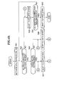
- FIG. 1 shows in block diagram the construction of a power circuit of the speaker apparatus of this embodiment.
- the speaker apparatus 1 includes a USB power input circuit 11, an AC adapter power input circuit 12, first and second regulators 13, 18, first to third switches 14 to 16, a DC-DC converter 17, first and second current limiting circuits 19, 20, a CPU 21, a digital circuit 22, an analog circuit 23, a power amplifier 24, and a capacitor 25.
- the first and second regulators 13, 18 will be referred to as the first and second LDOs 13, 18, and the first to third switches 14 to 16 will be referred to as the HSSW 14, the second SW 15, and the third SW 16, respectively.
- the CPU 21 is a control unit for performing overall control of the speaker apparatus 1.
- the digital circuit 22 and the analog circuit 23 perform various audio processing. After being processed in the digital circuit 22 and the analog circuit 23, an audio signal is amplified by the power amplifier 24 and emitted as a sound to the outside.
- the USB power input circuit 11 is an interface circuit that can be connected to a USB port of a host device 30.
- the host device 30 is, e.g., an information processing apparatus such as a PC.
- the USB power input circuit 11 is supplied with electric power of 100 mA or 500 mA from the USB port.
- the speaker apparatus 1 is driven with bus power when an electric current input from the USB power input circuit 11 is supplied to the CPU 21, the digital circuit 22, and the analog circuit 23.
- a USB device when connected with the host device 30 is supplied with electric power of 100 mA from the host device 30. Subsequently, if a negotiation with the host device 30 is established, the USB device can be supplied with electric power of 500 mA. If the negotiation cannot be established, the USB device remains supplied with electric power of 100 mA.
- the AC adapter power input circuit 12 is an interface circuit that can be connected to the AC adapter 40, and is supplied with electric power of, e.g., about 700 mA from the AC adapter 40.
- the speaker apparatus 1 is driven with self power when an electric current input from the AC adapter power input circuit 12 is supplied to the CPU 21, the digital circuit 22, and the analog circuit 23.
- the first LDO 13 is turned on and off in conjunction with power supply from the power input circuits 11, 12. When supplied with electric power from the USB power input circuit 11, the first LDO 13 is turned on and stabilizes an output voltage of the circuit 11 at 3.3 V. The first LDO 13 is turned off when supplied with electric power from the AC adapter power input circuit 12.
- the HSSW 14 which is a switch circuit controlled by the CPU 21, is turned on in the case of the bus-powered driving. Otherwise, the HSSW 14 is turned off.
- the second SW 15, which is a switch circuit controlled by the CPU 21, is turned on in the case of the bus-powered driving.
- the third SW 16 is turned on when supplied with electric power from the AC adapter power input circuit 12.
- the DC-DC converter 17 for voltage transformation transforms a voltage to be supplied to the digital circuit 22 and the CPU 21 from 5 V to 3.3 V.
- the second LDO 18 is normally turned on and stabilizes a voltage to be supplied to the analog circuit 23 at 3.3 V.
- the first and second current limiting circuits 19, 20 limit an electric current to be supplied to the power amplifier 24 and the capacitor 25.
- the first current limiting circuit 19 limits its output current to 100 mA
- the second current limiting circuit 20 limits its output current to 150 mA.
- the capacitor 25 is an electric double layer capacitor that has an extremely large electrostatic capacity (e.g., not less than several tens of ⁇ F). Since the capacitor 25 has an extremely large electrostatic capacity, the CPU 21, etc. become inoperable, if an electric current from the USB power input circuit 11 and/or from the AC adapter power input circuit 12 is all consumed for charging the capacitor 25. To ensure operations of various circuits of the speaker apparatus, the first and second current limiting circuits 19, 20 are provided at a stage preceding the capacitor 25 to limit an electric current supplied to the capacitor.
- electric power is stored in the capacitor 25 so that the stored electric power can be supplied from the capacitor 25 to the power amplifier 24 when the speaker apparatus 1 emits sounds while instantaneously consuming electric power of about several watts.
- the speaker apparatus 1 of this embodiment performs ON/OFF switching of the first LDO 13, the HSSW 14, the second SW 15, and the third SW 16 in accordance with the form of electric power supply from the USB power input circuit 11 and/or the AC adapter power input circuit 12, while storing electric power in the large-capacity capacitor 25. Nevertheless, if sound emission is continued and the power amplifier 24 continuously consumes electric power, a voltage across the capacitor 25 can decrease to or below a drive limit value (e.g., 2.7 V or less). In this embodiment, therefore, various operations are performed to suppress the voltage reduction.
- a drive limit value e.g., 2.7 V or less
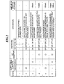
- FIG. 2 shows the ON/OFF actions of the first LDO 13 and the first to third SWs 14 to 16 and the action of the CPU 21 in respective ones of six operation states of the speaker apparatus 1.
- the speaker apparatus 1 is switched between its first to sixth operation states in accordance with the form of electric power supply from the power input circuits 11, 12. Specifically, the speaker apparatus 1 is switched to the first operation state, if electric power is supplied neither from the USB power input circuit 11 nor from the AC adapter power input circuit 12, i.e., if neither the host device 30 nor the AC adapter 40 is connected to the speaker apparatus 1.
- the CPU 21 In the first operation state, the CPU 21 is not driven and the switches 13 to 16 remain OFF.
- the speaker apparatus 1 When the speaker apparatus 1 is connected to the host device 30 so that an electric current of 100 mA is input from the USB power input circuit 11 to the speaker apparatus 1, the speaker apparatus 1 is switched to the second operation state. In the second operation state, the first LDO 13 is turned on and electric power is supplied to the CPU 21 via the LDO 13, and as a result, the CPU 21 is activated. The CPU 21 performs negotiation with the host device 30. If the negotiation is not successful, the CPU 21, determining that the speaker apparatus 1 cannot be driven, turns off the power switches 14 to 16, and switches the speaker apparatus 1 to the first operation state.
- the third operation state electric power input from the USB power input circuit 11 is supplied to the digital circuit 22, the analog circuit 23, and the first current limiting circuit 19, and electric power of 5V is supplied to the power amplifier 24.
- the speaker apparatus 1 is driven with bus power.
- the first current limiting circuit 19 limits its output current to 100 mA and supplies the output current to the power amplifier 24. With this current, the capacitor 25 is charged. When the voltage of the capacitor 25 increases to about 2. 7 V, sufficient electric power (electric current exceeding 100 mA) can be supplied to the power amplifier 24 even in the bus-powered driving. In practice, taking into account of a margin, the voltage may be increased to about 3 V to 3.5 V before being used for the driving.
- the power amplifier 24 is supplied with an electric current of 100 mA from the first current limiting circuit 19, and amplifies an audio signal. Depending on the degree of amplification, the power amplifier 24 sometimes consumes an electric current exceeding 100 mA. In that case, the capacitor 25 supplies deficient current. If the power amplifier 24 consumes an electric current exceeding 100 mA, the voltage of the capacitor 25 decreases. However, since an electric current of 100 mA is always supplied from the first current limiting circuit 19, the capacitor 25 is again charged when the current consumption by the power amplifier 24 decreases. Even in the bus-powered driving, the speaker apparatus 1 is therefore able to instantaneously output electric power of about several watts, whereby stable driving can be achieved.
- the CPU 21 After being activated, the CPU 21 turns off the first LDO 13, the HSSW 14, and the second SW 15. As a result, electric power input from the AC adapter power input circuit 12 is supplied to the digital circuit 22, the analog circuit 23, and the second current limiting circuit 20, and electric power of 5V is supplied to the power amplifier 24. Thus, the speaker apparatus 1 is driven with self power.
- the second current limiting circuit 20 limits its output current to 150 mA, and supplies the resultant output current to the power amplifier 24.
- the capacitor 25 is charged by the output current. As previously described, when the voltage of the capacitor 25 increases to about several volts, sufficient electric power can be supplied to the power amplifier 24.
- the power amplifier 24 is supplied with an electric current of 150 mA from the second current limiting circuit 20, and amplifies an audio signal. Depending on the degree of amplification, the power amplifier 24 sometimes consumes an electric current exceeding 150 mA. In that case, the capacitor 25 supplies deficient current. If the power amplifier 24 consumes electric current exceeding 150 mA, the voltage of the capacitor 25 decreases. However, since an electric current of 150 mA is always supplied from the second current limiting circuit 20, the capacitor 25 is again charged when the current consumption by the power amplifier 24 becomes small. Accordingly, the speaker apparatus 1 can be driven more stably than in the case of the bus-powered driving.
- the speaker apparatus 1 When the speaker apparatus 1 is connected to the host device 30 in the self-powered driving state, an electric current of 100 mA is supplied from the USB power input circuit 11, and the speaker apparatus 1 is switched to the fifth operation state.
- the CPU 21 performs negotiation with the host device 30. If the negotiation is unsuccessful, the speaker apparatus 1 is driven with self power, while maintaining the switches in their ON/OFF states assumed in the fourth operation state.
- the speaker apparatus 1 is switched to the sixth operation state.
- the CPU 21 turns on the HSSW 14, and supplies the first current limiting circuit 19 with an electric current input from the USB power input circuit 11.
- an electric current of 100 mA is supplied from the first current limiting circuit 19 to the power amplifier 24, and an electric current of 150 mA is supplied from the second current limiting circuit 20 to the power amplifier 24.
- an electric current of 250 mA is supplied to the power amplifier 24 and the capacitor 25.
- the speaker apparatus 1 is driven with both bus power and self power.
- the CPU 21 turns on the third SW 16 and turns off the first LDO 13 and the second SW 15, so that the speaker apparatus 1 is switched to the sixth operation state.
- FIGS. 3A , 3B , and 4A to 4C show in flowchart the procedures of an operation state switching process performed by the speaker apparatus 1.
- FIGS. 3A and 3B show in flowchart the procedures of operation in a case where the speaker apparatus 1 is connected to the host device 30, and
- FIGS. 4A to 4C show in flowchart the procedures of operation in a case where the AC adapter 40 is connected to the speaker apparatus.
- step S11 when the speaker apparatus 1 is USB connected to the host device 30, the first LDO 13 is turned on so that the CPU 21 is activated (step S11). Subsequently, the CPU 21 performs a negotiation with the host device 30 (step S12). If the negotiation is established, the speaker apparatus 1 is switched to the third operation state where the apparatus is driven with bus power (steps S12 and S13).
- step S14 whether the AC adapter 40 is connected to the speaker apparatus 1 is determined. If the AC adapter 40 is not connected, it is determined whether USB connection between the speaker apparatus 1 and the host device 30 is disconnected (step S15). If the USB connection is not disconnected, the flow returns to step S14. On the other hand, if the USB connection is disconnected, the speaker apparatus 1 is switched to the first operation state (step S16), and the operation state switching process is completed (whereby a power off state is entered).
- step S14 If it is determined in step S14 that the AC adapter 40 is connected to the speaker apparatus 1, the first LDO 13 is turned off and the third SW 16 is turned on (step S17). Then, the system of the speaker apparatus 1 is once reset (step S18), and the speaker apparatus 1 is switched to the sixth operation state (step S19), so that the speaker apparatus 1 is driven with both bus power and self power.
- step S20 whether USB connection is disconnected is determined. If the USB connection is not disconnected, it is determined whether the AC adapter connection is disconnected (step S21). If it is determined in step S20 that the USB connection is disconnected, the speaker apparatus 1 is switched to the fourth operation state (step S22), whereupon the operation state switching process is completed (whereby electric power remains ON).
- step S21 If it is determined in step S21 that AC adapter connection is disconnected, the first LDO 13 is turned on and the third SW 16 is turned off (step S23). Then, the system is once reset (step S24), and the flow proceeds to step S13 in which the speaker apparatus 1 is switched to the third operation state where the apparatus is driven with bus power.
- step S12 If it is determined in step S12 that the CPU 21 has failed to establish a negotiation with the host device 30, the speaker apparatus 1 is switched to the second operation state (step S31), and whether the AC adapter 40 is connected to the speaker apparatus 1 is determined (step S32). If the AC adapter 40 is not connected, the speaker apparatus 1 is switched to the first operation state (step S33), whereupon the operation state switching process is completed (whereby a power off state is entered).
- step S34 If the AC adapter 40 is connected, the third SW 16 is turned on (step S34), and the speaker apparatus 1 is switched to the fifth operation state (step S35) in which the apparatus is driven with self power. Subsequently, whether the USB connection is disconnected is determined (step S36). If the USB connection is not disconnected, whether the AC adapter connection is disconnected is determined (step S37). If it is determined in step S36 that the USB connection is disconnected, the speaker apparatus 1 is switched to the fourth operation state (step S22), and the operation state switching process is completed (whereby electric power remains ON).
- step S37 If it is determined in step S37 that the AC adapter connection is disconnected, the first LDO 13 is turned on and the third SW 16 is turned off (S38). Then, the system is once reset (S39), and the flow proceeds to step S31 in which the speaker apparatus 1 is switched to the second operation state.
- step S51 the third SW 16 is turned on so that the CPU 21 is activated.
- step S52 whether the speaker apparatus 1 is USB connected to the host device 30 is determined. If the speaker apparatus is not USB connected to the host device, the speaker apparatus 1 is switched to the fourth operation state (step S53), and whether the AC adapter connection is disconnected is determined (step S54). If the AC adapter connection is not disconnected, the flow proceeds to step S52 in which whether the speaker apparatus 1 is USB connected to the host device 30 is determined. If it is determined in step S54 that the AC adapter connection is disconnected, the speaker apparatus 1 is switched to the first operation state (step S55), and the operation state switching process is completed.
- step S52 if it is determined in step S52 that the speaker apparatus 1 is USB connected to the host device 30, the CPU 21 performs a negotiation with the host device 30 (step S56). If the negotiation is established, the speaker apparatus 1 is switched to the sixth operation state where the apparatus is driven with both bus power and self power (step S57).
- step S58 it is determined whether the AC adapter connection is disconnected. If the AC adapter connection is not disconnected, whether the USB connection is disconnected is determined (step S59). If it is determined in step S59 that the USB connection is disconnected, the flow proceeds to step S53 in which the speaker apparatus 1 is switched to the fourth operation state.
- step S58 If it is determined in step S58 that the AC adapter connection is disconnected, the first LDO 13 is turned on and the third SW 16 is turned off (step S60). Then, the system is once reset (step S61), and the speaker apparatus 1 is switched to the third operation state (step S62) in which the apparatus is driven with bus power.
- step S63 whether the USB connection is disconnected is determined. If the USB connection is not disconnected, whether the AC adapter 40 is connected to the speaker apparatus 1 is determined (step S65). If the USB connection is disconnected, the flow proceeds to step S64 in which the speaker apparatus 1 is switched to the first operation state, and the operation state switching process is completed (whereby electric power is turned off).
- step S65 If it is determined in step S65 that the AC adapter 40 is connected, the first LDO 13 is turned off and the third SW 16 is turned on (step S66). Then, the system is once reset (step S67), and the flow proceeds to step S57 in which the speaker apparatus 1 is switched to the sixth operation state where the apparatus is driven with both bus power and self power.
- step S56 If it is determined in step S56 that a negotiation with the host device 30 cannot be established, the CPU 21 switches the speaker apparatus 1 to the fifth state where the apparatus is driven with self power (step S68). Then, whether the AC adapter connection is disconnected is determined (step S69), and whether the USB connection is disconnected is determined (step S70). If it is determined in step S70 that the USB connection is disconnected, the flow proceeds to step S53 in which the speaker apparatus 1 is switched to the fourth operation state.
- step S69 If it is determined in step S69 that the AC adapter connection is disconnected, the first LDO 13 is turned on and the third SW 16 is turned off (step S71). Then, the system is once reset (step S72), and the speaker apparatus 1 is switched to the second operation state (step S73). Subsequently, whether the USB connection is disconnected is determined (step S74). If the USB connection is disconnected, the flow proceeds to step S64 in which the speaker apparatus 1 is switched to the first operation state, and the operation state switching process is completed (whereby electric power is turned off).
- step S75 If the USB connection is not disconnected, whether the AC adapter 40 is connected to the speaker apparatus 1 is confirmed (step S75). If the AC adapter 40 is connected, the first LDO 13 is turned off and the third SW 16 is turned on (step S76). Then, the system is once reset (step S77), and the flow proceeds to step S68 in which the speaker apparatus 1 is switched to the fifth operation state so as to be driven with self power.
- switching is made between the bus-powered driving, the self-powered driving, and the bus and self-powered driving, thereby switching an amount of electric power (especially, electric current) supplied from the first and second current limiting circuits 19, 20 to the capacitor 25, whereby a stable operation can be realized while ensuring an amount of electric power (especially, electric current) supplied to the power amplifier.
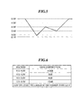
- FIG. 5 shows a change in voltage of the capacitor 25 with change in power consumption of the power amplifier 24.
- the capacitor 25 is supplied with a voltage of 5 V from the USB power input circuit 11 or from the AC adapter power input circuit 12, and therefore the capacitor 25 is charged to 5 V at the maximum. If the power amplifier 24 does not consume electric power (or is driven at or below 100 mA or 150 mA), the voltage across the capacitor 25 is maintained at 5 V.
- the inclination of voltage reduction is made small as shown by a two-dotted chain line when an emitted sound volume is made smaller than in the case of sound emission accompanied by a voltage reduction shown by one-dotted chain line in FIG. 5 . If no sound is emitted, an electric current supplied to the capacitor 25 remains unchanged at 100 mA or 150 mA, and the voltage increasing inclination is as shown by a dotted line, which is not different from that shown by a solid line.
- a predetermined value e.g., 2. 7 V
- the following processing is performed to prevent the output of the power amplifier 24 from going down.
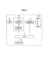
- FIG. 6 shows the concept of gain control for the power amplifier performed in accordance with the voltage of the capacitor 25, and FIG. 7 shows in block diagram an audio signal processing system of the speaker apparatus 1.
- the speaker apparatus 1 includes, as the audio signal processing system, a signal processing circuit 200 and a speaker system 100 having two speaker units 100A, 100B. Audio information input from the USB interface 101 is input, as a digital audio signal, to the signal processing circuit 200.
- the signal processing circuit 200 comprised of the digital circuit 22 and the analog circuit 23 performs level correction and phase control of the input digital audio signal, and outputs an analog audio signal to the power amplifier 24.
- the analog audio signal amplified by the power amplifier 24 is emitted as a sound from the speaker system 100.
- the signal processing circuit 200, the power amplifier 24, and the capacitor 25 are connected to the CPU 21.
- the CPU 21 controls the way of processing by the signal processing circuit 200 and controls the gain of the power amplifier 24.
- the voltage of the capacitor 25 is also managed by the CPU 21. As shown in FIG. 6 , if the voltage of the capacitor 25 is in a range from 4.5 V to 5 V, the CPU 21 does not correct the gain of the power amplifier 24 ( ⁇ 0 dB). Specifically, since the voltage of the capacitor 25 is sufficiently high, the gain correction is not performed, and an audio signal input from the USB interface 101 is amplified with a prescribed gain by the power amplifier 24 and then emitted as a sound.
- the CPU 21 corrects the gain of the power amplifier 24 by -3 dB. By correcting the gain by -3 dB, sound volume is made small and the power consumption by the power amplifier 24 becomes small. As a result, the inclination of reduction of the voltage of the capacitor 25 becomes small. If the voltage of the capacitor 25 is in a range from 3.5 V to 4 V, the CPU 21 corrects the gain by -6 dB. If the voltage of the capacitor 25 is in a range from 3 V to 3.5 V, the gain is corrected by -12 dB. The lower the voltage value of the capacitor 25 is, the larger the gain correction (and consequently the smaller the sound volume) will be.
- the inclination of reduction of the voltage of the capacitor 25 becomes further small, whereby the reduction of the voltage of the capacitor 25 can be suppressed.
- the audio signal is muted so that the power consumption by the power amplifier 24 becomes zero.
- muting is continued until the voltage is restored to some extent (e.g., 3. 5 V).
- the audio signal is muted, the power consumption by the power amplifier 24 becomes zero, and therefore the voltage value of the capacitor 25 is immediately restored.
- muting and muting releasing are alternately repeated.
- a muting releasing level is set to be equal to or higher than 3. 5 V, taking into account of a margin.
- the gain of the power amplifier 24 is corrected in accordance with a voltage value of the capacitor 25, whereby the output of the power amplifier 24 is prevented from going down.
- the reproduction mode is switched between a mode for stereo reproduction of audio signal and a mode for monaural reproduction (one channel reproduction) of audio signal. Also, switching is made between a mode where the phase control of audio signal is performed using the two speaker units 100A, 100B to reproduce the audio signal such that a virtual sound source will be generated and a mode where audio signal is reproduced without making the phase control.
- the CPU 21 makes settings such that phase control is performed by the signal processing circuit 200 on audio signal, and reproduces the audio signal such that a virtual sound source will be generated. If the voltage of the capacitor 25 decreases in some extent, the CPU 21 makes settings such that the phase control is not performed by the signal processing circuit 200, and switching is made to normal stereo reproduction. If the voltage of the capacitor 25 further decreases, the CPU 21 inhibits audio signal supply to either the speaker unit 100A or 100B (or mutes the audio signal for either channel), and performs switching to monaural reproduction.
- the required gain is about two times as high as a gain required to obtain the same sound pressure in the normal stereo reproduction, and thus the inclination of reduction in voltage of the capacitor 25 becomes large.
- the monaural reproduction it is enough to give electric power for driving a one-channel speaker, and therefore, the inclination of reduction of voltage of the capacitor 25 becomes small.
- the above-described reproduction mode switching is performed in accordance with a voltage value of the capacitor 25, to prevent the output of the power amplifier 24 from going down.
- the audio signal reproduction mode can be switched in accordance with the form of electric power supply from the USB power input circuit 11 and the AC adapter power input circuit 12. For example, when the speaker apparatus 1 is driven with bus power, monaural reproduction of audio signal is performed. When the speaker apparatus is driven with self power, stereo reproduction of audio signal is performed. When the speaker apparatus is driven with both bus power and self power, audio signal is reproduced such as to generate a virtual sound source.
- reproduction mode can be switched while making the gain correction.
- the speaker apparatus has been described as the electronic device.
- this invention is applicable to any electronic device so long as it can be driven with bus power via USB connection and with self power via AC adapter.
- the form of electric power supply is switched between bus-powered driving and self-powered driving.
- the described construction is not essentially required, but also applicable to an ordinary electronic device that performs ordinary power supply (that does not comprise a power supply switching function).
- the battery voltage lowers with elapse of use time.
- a power amplifier output is saturated at a small signal level or the operation of electronic device stops.
- the amplifier gain correction or the audio signal reproduction mode is switched in accordance with a voltage value of the capacitor.
- the gain correction or the reproduction mode can be switched in accordance with a voltage value of the power amplifier.
- the electronic device of this invention it is possible to prevent operation stop caused by a reduction of device operation voltage, and to realize a stable operation while ensuring an amount of electric power supply (especially, an amount of electric current supply) to the electronic device.
Landscapes
- Engineering & Computer Science (AREA)
- Power Engineering (AREA)
- Direct Current Feeding And Distribution (AREA)
- Amplifiers (AREA)
Applications Claiming Priority (3)
| Application Number | Priority Date | Filing Date | Title |
|---|---|---|---|
| JP2007251923A JP5369415B2 (ja) | 2007-09-27 | 2007-09-27 | スピーカ装置 |
| JP2007261899A JP5298492B2 (ja) | 2007-10-05 | 2007-10-05 | 電子機器 |
| PCT/JP2008/067971 WO2009041717A1 (ja) | 2007-09-27 | 2008-09-26 | 電子機器 |
Publications (1)
| Publication Number | Publication Date |
|---|---|
| EP2197105A1 true EP2197105A1 (de) | 2010-06-16 |
Family
ID=40511589
Family Applications (1)
| Application Number | Title | Priority Date | Filing Date |
|---|---|---|---|
| EP08834326A Withdrawn EP2197105A1 (de) | 2007-09-27 | 2008-09-26 | Elektronische vorrichtung |
Country Status (4)
| Country | Link |
|---|---|
| US (1) | US20100246857A1 (de) |
| EP (1) | EP2197105A1 (de) |
| CN (1) | CN101803187B (de) |
| WO (1) | WO2009041717A1 (de) |
Cited By (3)
| Publication number | Priority date | Publication date | Assignee | Title |
|---|---|---|---|---|
| EP2782211A4 (de) * | 2011-11-18 | 2015-07-01 | Sony Corp | Elektronische vorrichtung, ladungssteuerungsverfahren, ladesystem und datenübertragungssystem |
| US9582056B2 (en) | 2015-02-06 | 2017-02-28 | Axis Ab | Method for amplifying a signal and amplifying device |
| CN107925389A (zh) * | 2015-08-24 | 2018-04-17 | 雅马哈株式会社 | 信号处理装置和扬声器装置 |
Families Citing this family (16)
| Publication number | Priority date | Publication date | Assignee | Title |
|---|---|---|---|---|
| CN101751057B (zh) * | 2008-12-09 | 2012-01-25 | 佛山普立华科技有限公司 | 电子设备供电电路及其供电方法 |
| US8219729B1 (en) * | 2010-01-11 | 2012-07-10 | Cypress Semiconductor Corporation | Enumeration circuits, structures and methods for host connected devices |
| JP5240281B2 (ja) * | 2010-11-29 | 2013-07-17 | オムロン株式会社 | 温度調節器 |
| US9119159B2 (en) * | 2011-01-10 | 2015-08-25 | Qualcomm Incorporated | Battery power monitoring and audio signal attenuation |
| US9047086B1 (en) * | 2011-03-21 | 2015-06-02 | Marvell International Ltd. | Method and apparatus for supplying power to a device over a communication link |
| CN103107575B (zh) | 2013-01-18 | 2015-07-29 | 华为终端有限公司 | 充电方法、移动设备、充电设备与充电系统 |
| CN104345855B (zh) * | 2013-08-05 | 2017-11-24 | 山东比特智能科技股份有限公司 | 用于usb接口的限流电路 |
| KR102147243B1 (ko) | 2013-11-04 | 2020-08-24 | 삼성전자 주식회사 | 전자장치의 충전 장치 및 방법 |
| JP5827987B2 (ja) * | 2013-11-28 | 2015-12-02 | アンリツ株式会社 | 移動体端末試験装置および試験方法 |
| WO2016030725A1 (en) * | 2014-08-29 | 2016-03-03 | Pismo Labs Technology Limited | Apparatus and method for a mobile router to receive power from a plurality of power supplies |
| US10411466B2 (en) | 2014-12-21 | 2019-09-10 | Pismo Lab Technology Limited | Apparatus and method for a mobile router to receive power from a plurality of power supplies |
| JP6690171B2 (ja) * | 2015-09-28 | 2020-04-28 | ヤマハ株式会社 | 電子機器 |
| JP6891444B2 (ja) * | 2016-10-19 | 2021-06-18 | ヤマハ株式会社 | 回路および楽器 |
| DE102016224861B3 (de) * | 2016-12-13 | 2018-03-08 | Siemens Schweiz Ag | Stellantrieb mit einer USB-Schnittstelle zur Übertragung von Konfigurationsdaten und/oder Diagnosedaten zwischen einem Stellantrieb und einem angeschlossenen Bediengerät im stromlosen oder ausgeschalteten Zustand des Stellantriebs |
| FI20195731A1 (en) | 2019-09-04 | 2021-03-05 | Genelec Oy | Audio amplifier for use with a limited power source |
| US12149113B2 (en) * | 2023-01-05 | 2024-11-19 | Atmosic Technologies, Inc. | Dynamically selectable power configurations |
Family Cites Families (9)
| Publication number | Priority date | Publication date | Assignee | Title |
|---|---|---|---|---|
| US5692050A (en) * | 1995-06-15 | 1997-11-25 | Binaura Corporation | Method and apparatus for spatially enhancing stereo and monophonic signals |
| JP2002189486A (ja) * | 2000-12-20 | 2002-07-05 | Matsushita Electric Ind Co Ltd | 携帯型オーディオ再生装置 |
| JP4928027B2 (ja) * | 2001-07-02 | 2012-05-09 | キヤノン株式会社 | 電子機器 |
| JP3974351B2 (ja) * | 2001-07-04 | 2007-09-12 | ペンタックス株式会社 | 電源装置 |
| JP2005072983A (ja) * | 2003-08-25 | 2005-03-17 | Matsushita Electric Ind Co Ltd | 音声信号増幅装置及び音響装置 |
| JP2005141732A (ja) | 2003-10-15 | 2005-06-02 | Teac Corp | インターフェース端子を具備する電子機器及びこれに接続される電源供給ケーブル |
| US7329969B2 (en) * | 2003-10-15 | 2008-02-12 | Teac Corporation | Electronic device including interface terminal and power supply cable connected thereto |
| US20060050902A1 (en) * | 2004-09-07 | 2006-03-09 | Galax Multimedia Co., Ltd. | Portable audio playing device |
| US7498694B2 (en) * | 2006-04-12 | 2009-03-03 | 02Micro International Ltd. | Power management system with multiple power sources |
-
2008
- 2008-09-26 EP EP08834326A patent/EP2197105A1/de not_active Withdrawn
- 2008-09-26 US US12/733,708 patent/US20100246857A1/en not_active Abandoned
- 2008-09-26 CN CN200880108141.8A patent/CN101803187B/zh not_active Expired - Fee Related
- 2008-09-26 WO PCT/JP2008/067971 patent/WO2009041717A1/ja not_active Ceased
Non-Patent Citations (1)
| Title |
|---|
| See references of WO2009041717A1 * |
Cited By (6)
| Publication number | Priority date | Publication date | Assignee | Title |
|---|---|---|---|---|
| EP2782211A4 (de) * | 2011-11-18 | 2015-07-01 | Sony Corp | Elektronische vorrichtung, ladungssteuerungsverfahren, ladesystem und datenübertragungssystem |
| US9582056B2 (en) | 2015-02-06 | 2017-02-28 | Axis Ab | Method for amplifying a signal and amplifying device |
| CN107925389A (zh) * | 2015-08-24 | 2018-04-17 | 雅马哈株式会社 | 信号处理装置和扬声器装置 |
| EP3343766A4 (de) * | 2015-08-24 | 2019-07-17 | Yamaha Corporation | Signalverarbeitungsvorrichtung und lautsprechervorrichtung |
| US10418956B2 (en) | 2015-08-24 | 2019-09-17 | Yamaha Corporation | Signal processing apparatus, speaker apparatus, and signal processing method |
| CN107925389B (zh) * | 2015-08-24 | 2021-08-06 | 雅马哈株式会社 | 信号处理装置、扬声器装置和信号处理方法 |
Also Published As
| Publication number | Publication date |
|---|---|
| WO2009041717A1 (ja) | 2009-04-02 |
| CN101803187B (zh) | 2014-06-25 |
| US20100246857A1 (en) | 2010-09-30 |
| CN101803187A (zh) | 2010-08-11 |
Similar Documents
| Publication | Publication Date | Title |
|---|---|---|
| EP2197105A1 (de) | Elektronische vorrichtung | |
| EP2443744B1 (de) | Verfahren und schaltung zur kontrolle eines audio-ausgangs-signales eines batteriebetriebnen gerätes | |
| US12101612B2 (en) | Smart speaker power management | |
| US8224399B2 (en) | Method and apparatus to supply power voltage to a mobile device in a variable manner | |
| US9231543B2 (en) | Audio power amplification with reduced input power supply crest factor | |
| JP5816482B2 (ja) | 音声記録再生装置 | |
| CN106878863A (zh) | 供电电源和功放系统和功放系统的电压调整方法 | |
| US9301046B1 (en) | Systems and methods for minimizing distortion in an audio output stage | |
| JP5298492B2 (ja) | 電子機器 | |
| CN107864435B (zh) | 音频功率的控制方法、控制电路和音频设备 | |
| CN115209311A (zh) | 降低扬声器系统功耗的装置、控制方法及可穿戴设备 | |
| JP5125462B2 (ja) | 電子機器および音声再生装置 | |
| JP5369415B2 (ja) | スピーカ装置 | |
| CN102026061B (zh) | 音频处理装置和方法 | |
| US9543908B2 (en) | Adaptive rail voltage regulation on power supplies | |
| EP1047187B1 (de) | Vorverstärkerschaltung | |
| JPS62502773A (ja) | 電圧源/電流源装置 | |
| JP2016054438A (ja) | オーディオ装置 | |
| EP1959566B1 (de) | Verfahren und Vorrichtung zur Steuerung des Audiosignal-Ausgabeniveaus eines tragbaren Audiogerätes | |
| JP2006157409A (ja) | オーディオ増幅装置 | |
| US9888310B2 (en) | Audio equipment | |
| JP6789497B2 (ja) | 音楽再生装置 | |
| JP2898459B2 (ja) | 音量コントロール回路 | |
| US20070236974A1 (en) | Amplification Apparatus | |
| JP4230332B2 (ja) | オーディオ機器およびオーディオシステム |
Legal Events
| Date | Code | Title | Description |
|---|---|---|---|
| PUAI | Public reference made under article 153(3) epc to a published international application that has entered the european phase |
Free format text: ORIGINAL CODE: 0009012 |
|
| 17P | Request for examination filed |
Effective date: 20100322 |
|
| AK | Designated contracting states |
Kind code of ref document: A1 Designated state(s): AT BE BG CH CY CZ DE DK EE ES FI FR GB GR HR HU IE IS IT LI LT LU LV MC MT NL NO PL PT RO SE SI SK TR |
|
| AX | Request for extension of the european patent |
Extension state: AL BA MK RS |
|
| DAX | Request for extension of the european patent (deleted) | ||
| STAA | Information on the status of an ep patent application or granted ep patent |
Free format text: STATUS: THE APPLICATION HAS BEEN WITHDRAWN |
|
| 18W | Application withdrawn |
Effective date: 20130429 |