EP2197123A1 - Netzleitung-Kommunikationsvorrichtung und Steuerungsverfahren dafür - Google Patents
Netzleitung-Kommunikationsvorrichtung und Steuerungsverfahren dafür Download PDFInfo
- Publication number
- EP2197123A1 EP2197123A1 EP09177651A EP09177651A EP2197123A1 EP 2197123 A1 EP2197123 A1 EP 2197123A1 EP 09177651 A EP09177651 A EP 09177651A EP 09177651 A EP09177651 A EP 09177651A EP 2197123 A1 EP2197123 A1 EP 2197123A1
- Authority
- EP
- European Patent Office
- Prior art keywords
- plc apparatus
- state
- network
- plc
- working state
- Prior art date
- Legal status (The legal status is an assumption and is not a legal conclusion. Google has not performed a legal analysis and makes no representation as to the accuracy of the status listed.)
- Granted
Links
Images


Classifications
-
- H—ELECTRICITY
- H04—ELECTRIC COMMUNICATION TECHNIQUE
- H04B—TRANSMISSION
- H04B3/00—Line transmission systems
- H04B3/54—Systems for transmission via power distribution lines
- H04B3/542—Systems for transmission via power distribution lines the information being in digital form
-
- H—ELECTRICITY
- H04—ELECTRIC COMMUNICATION TECHNIQUE
- H04B—TRANSMISSION
- H04B2203/00—Indexing scheme relating to line transmission systems
- H04B2203/54—Aspects of powerline communications not already covered by H04B3/54 and its subgroups
- H04B2203/5429—Applications for powerline communications
- H04B2203/5458—Monitor sensor; Alarm systems
Definitions
- the present disclosure relates to the field of communication, and particularly to a Power Line Communication (PLC) apparatus and a method for controlling the PLC apparatus.
- PLC Power Line Communication
- PLC Power Line Communication
- the inventor finds that the existing technology has at least the following problems.
- the power source of the PLC apparatus converts the Alternating Current (AC) utility power (100 ⁇ 240 V AC) into the working voltage required by the PLC apparatus.
- AC Alternating Current
- the useful power of the power conversion is relatively low, and up to 75%, Home users usually need not to continuously use the PLC apparatus all day long, but even if the PLC apparatus is not used, the power source will continuously convert the AC utility power in case that the power source of the PLC apparatus is not turned off, and thus the electric energy is wasted.
- power consumption of the power source of the PLC apparatus is high, and much heat is generated, so the working state of the PLC apparatus is unstable due to the excessively high temperature.
- the PLC apparatus has various chips therein, such as a power source chip that provides power conversion of the AC utility power (100 ⁇ 240 V AC) to ensure electric supply for the PLC apparatus during working; a network transmission chip that carries out Ethernet line signal input/output and modulation/demodulation to ensure transmission of network signal over the line.
- a power source chip that provides power conversion of the AC utility power (100 ⁇ 240 V AC) to ensure electric supply for the PLC apparatus during working
- a network transmission chip that carries out Ethernet line signal input/output and modulation/demodulation to ensure transmission of network signal over the line.
- the PLC apparatus when not being used by the user, the PLC apparatus shall be manually powered off, or even pulled off. When the PLC apparatus is to be used at a next time, it shall be manually powered on.
- the technical problem to be solved by the present disclosure is to provide a Power Line Communication (PLC) apparatus and a method for controlling the PLC apparatus, which enables the PLC apparatus to save electric energy automatically.
- PLC Power Line Communication
- An embodiment of the present invention provides a method for controlling a PLC apparatus, including:
- a PLC apparatus including:
- the working state of the PLC apparatus is automatically switched in accordance with the network state and the working state of the PLC apparatus, so that power consumption of the PLC apparatus can be reduced without manual intervention, and an unstable working state of the PLC apparatus due to an excessively high temperature can be avoided.
- Fig. 1 illustrates a method for controlling a Power Line Communication (PLC) apparatus according to a first embodiment of the present disclosure. The method is described as follows.
- PLC Power Line Communication
- step S11 the working state and the network state of the PLC apparatus is acquired.
- step S12 the working state of the PLC apparatus is switched in accordance with the working state and the network state of the PLC apparatus.
- the working state of the PLC apparatus is automatically switched in accordance with the working state and the network state of the PLC apparatus.
- the power consumption of the PLC apparatus can be reduced, and an unstable working state of the PLC apparatus due to an excessively high temperature can be avoided.
- Fig. 2 illustrates a method for controlling a PLC apparatus according to a second embodiment of the present disclosure. The method is described as follows.
- step S21 a timer is started. The process proceeds to a next step when the timer times out.
- the timer is capable of periodically generating a control signal to periodically detect the network state and the working state of the PLC apparatus, so as to set a frequency for judging whether or not to switch the working state of the PLC apparatus, and to reasonably configure the system resource occupied by the judging process.
- step S22 the working state of the PLC apparatus is acquired.
- the working state of the PLC apparatus after a previous switching can be recorded in a memory, and the current working state of the PLC apparatus can be acquired by reading the record in the memory.
- stepS23 a state of physical connection between the PLC apparatus and the network is detected.
- step S24 the network state of the PLC apparatus is judged in accordance with the state of physical connection between, the PLC apparatus and the network.
- the acquired network state of the PLC apparatus is "busy"; and when the state of physical connection between the PLC apparatus and the network is disconnected, the acquired network state of the PLC apparatus is "idle".
- step S25 the working state of the PLC apparatus is switched in accordance with the network state and the working state of the PLC apparatus.
- the step is performed by switching the PLC apparatus from the normal working state to a sleep state when the network state of the PLC apparatus is idle and the working state is normal, and switching the PLC apparatus from the sleep state to the normal working state when the network state of the PLC apparatus is busy and the working state is sleep.
- the normal working state of the PLC apparatus is that the PLC apparatus is powered by its main power source, which charges a battery of the PLC apparatus at the same time.
- the sleep state of the PLC apparatus is that the PLC apparatus is powered by its battery, In this case, when the PLC apparatus enters the normal working state from the sleep state, the main power source of the PLC apparatus charges the battery; when the PLC apparatus enters the sleep state from the normal working state, the battery firstly starts to supply power, and then a relay shuts off the main power source; and when the PLC apparatus enters the normal working state from the sleep state again, then relay switches to the main power source of the PLC apparatus, and at the same time, the battery is again being charged.
- the main power source needs not to convert the AC utility power, and power is supplied by the battery, so that the effective power of the PLC apparatus is improved and the electric energy is saved.
- the heat generated by the PLC apparatus is reduced, and the reliability of the PLC apparatus is improved.
- the relay of the PLC apparatus can be controlled to switch between the main power source and the battery by being provided a control signal.
- the normal working state of the PLC apparatus is that a chip of the PLC apparatus is in a maximum power consumption mode.
- the sleep state of the PLC apparatus is that the chip of the PLC apparatus is in a standby mode. In that case, when the PLC apparatus automatically switches to the sleep mode, the chip of the PLC apparatus is in the standby mode, the power consumption is low, and the electric energy is saved.
- the chip of the PLC apparatus may be a power source chip in the PLC apparatus, or a network transmission chip.
- the chip of the PLC apparatus can be controlled to switch between the standby mode and the maximum power consumption mode, by being provided with a control signal.
- the normal working state of the PLC apparatus is that the PLC apparatus is powered by its power source, which charges a battery of the PLC apparatus at the same time, and the chip of the PLC apparatus, is in a maximum power consumption mode.
- the steep stale of the PLC apparatus is that the PLC apparatus is powered by its battery and the chip of the PLC apparatus is in a standby mode.
- the chip of the PLC apparatus may be a power source chip in the PLC apparatus, or a network transmission chip. In this case, when the PLC apparatus automatically switches to the sleep mode, the power consumption of the PLC apparatus is the minimum, and the electric energy is saved at maximum.
- the network state of the PLC apparatus is firstly judged in accordance with the state of physical connection between the PLC apparatus and the network, and then the working state of the PLC apparatus is automatically switched in accordance with the network state and the working state of the PLC apparatus, so that the PLC apparatus is put into the sleep state when the network state of the PLC apparatus is idle, and the PLC apparatus is put into the normal working state when the network state of the PLC apparatus is busy, thereby saving electric energy without any manual interference.
- Fig. 3 illustrates a method for controlling a PLC apparatus according to a third embodiment of the present disclosure. The method is described as follows.
- step S31 a timer is started, and the process proceeds to a next step when the timer times out.
- step S32 a working state of the PLC apparatus is acquired.
- step S33 a traffic of network data passing the PLC apparatus is detected.
- step S34 a network state of the PLC apparatus is judged in accordance with the traffic of network data passing the PLC apparatus.
- the predetermined value can be set as several data packets, or 0 data packet.
- step S35 the working state of the PLC apparatus is switched in accordance with the network state and the working state of the PLC apparatus.
- the step is performed by switching the PLC apparatus from the normal working state to a sleep state when the network state of the PLC apparatus is idle and the working state is normal, and switching the PLC apparatus from the sleep state to the normal working state when the network state of the PLC apparatus is busy and the working state is sleep.
- the normal working state of the PLC apparatus is that the PLC apparatus is powered by its main power source, which charges a battery of the PLC apparatus at the same time that a chip of the PLC apparatus is in a maximum power consumption mode.
- the sleep state of the PLC apparatus is that the PLC apparatus is powered by its battery and/or that the chip of the PLC apparatus is in a standby mode.
- the network state of the PLC apparatus is firstly judged in accordance with the traffic of network data passing the PLC apparatus, and then the working state of the PLC apparatus is automatically switched in accordance with the network state and the working state of the PLC apparatus, so that the PLC apparatus is put into the sleep state when the network state of the PLC apparatus is idle, and the PLC apparatus is put into the normal working state when the network state of the PLC apparatus is busy, thereby saving electric energy without any manual interference.
- Fig. 4 illustrates a PLC apparatus 4 according to a fourth embodiment of the present disclosure.
- the PLC apparatus 4 includes:
- the working state of the PLC apparatus is switched in accordance with the network state and the working state of the PLC apparatus, so that the PLC apparatus is environment-protective and energy saving, thus the power consumption of the PLC apparatus is reduced, and the normal usage by the user will not be influenced. Meanwhile, the heat generated by the PLC apparatus is reduced, and the working stability and reliability are improved.
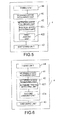
- Fig. 5 illustrates a PLC apparatus 4 according to a fifth embodiment of the present disclosure.
- the PLC apparatus 4 includes:
- the network state acquiring unit 42 includes:
- the switching unit 43 is further adapted to switch the PLC apparatus from the normal working state to a sleep state when the network state of the PLC apparatus is idle and the working state is normal, and switch the PLC apparatus from the sleep state to the normal working state when the network state of the PLC apparatus is busy and the working state is sleep.
- the normal working state of the PLC apparatus is that the PLC apparatus is powered by its main power source, which charges a battery of the PLC apparatus at the same time, and/or that a chip of the PLC apparatus is in a maximum power consumption mode.
- the chip of the PLC apparatus may be a power source chip in the PLC apparatus, or a network transmission chip.
- the sleep state of the PLC apparatus is that the PLC apparatus is powered by its battery and/or that the chip of the PLC apparatus is in a standby mode.
- the switching unit 43 provides a control signal to the chip of the PLC apparatus, so that the chip of the FLC apparatus is switched between the standby mode and the maximum power consumption mode.
- the switching unit 43 provides a control signal to the relay of the PLC apparatus to control the relay to switch between the main power source and the battery.
- the switching unit when the PLC apparatus enters the normal working state from the sleep state, the main power source of the PLC apparatus the battery; when the PLC apparatus, enters the sleep state from the normal working state, the switching unit firstly controls the battery to supply power, and then controls the relay to shut off the main power source of the PLC apparatus; and when the PLC apparatus enters the normal working state from the sleep state again, the switching unit controls the relay to switch to the main power source of the PLC apparatus, and the battery is again being charged.
- the network state acquiring unit 42 judges the network state of the PLC apparatus in accordance with the state of physical connection between the PLC apparatus and the network, and the switching unit 43 automatically switches the working state of the PLC apparatus in accordance with the network state and the working state of the PLC apparatus so as to put the PLC apparatus into the sleep state when the network state of the PLC apparatus is idle, and put the PLC apparatus into the normal working state when the network state of the PLC apparatus is busy, thereby saving electric energy without any manual interference.
- Fig. 6 illustrates a PLC apparatus 4 according to a sixth embodiment of the present disclosure.
- the PLC apparatus 4 includes:
- the network state acquiring unit 42 includes:
- the switching unit 43 is adapted to switch the PLC apparatus from the normal working state to a sleep state when the network state of the PLC apparatus is idle and the working state is normal, and switch the PLC apparatus from the sleep state to the normal working state when the network state of the PLC apparatus is busy and the working state is sleep.
- the normal working state of the PLC apparatus is that the PLC apparatus is powered by its main power source, which charges a battery of the PLC apparatus at the same time; and/or a chip of the PLC apparatus is in a maximum power consumption mode.
- the sleep state of the PLC apparatus is that the PLC apparatus is powered by its battery, and/or the chip of the PLC apparatus is in a standby mode.
- the network state acquiring unit 42 judges the network state of the PLC apparatus in accordance with the traffic of network data passing the PLC apparatus, and the switching unit 43 automatically switches the working state of the PLC apparatus in accordance with the network state and the working state of the PLC apparatus, so as to put the PLC apparatus into the state when the network state of the PLC apparatus is idle, and put the PLC apparatus into the normal working state when the network state of the PLC apparatus is busy, thereby saving electric energy without any manual interference.
Landscapes
- Engineering & Computer Science (AREA)
- Power Engineering (AREA)
- Computer Networks & Wireless Communication (AREA)
- Signal Processing (AREA)
- Cable Transmission Systems, Equalization Of Radio And Reduction Of Echo (AREA)
- Power Sources (AREA)
- Small-Scale Networks (AREA)
- Polyurethanes Or Polyureas (AREA)
- Programmable Controllers (AREA)
Applications Claiming Priority (1)
| Application Number | Priority Date | Filing Date | Title |
|---|---|---|---|
| CN200810239342.3A CN101771440B (zh) | 2008-12-10 | 2008-12-10 | 电力线通讯设备及其控制方法 |
Publications (2)
| Publication Number | Publication Date |
|---|---|
| EP2197123A1 true EP2197123A1 (de) | 2010-06-16 |
| EP2197123B1 EP2197123B1 (de) | 2011-02-09 |
Family
ID=41786158
Family Applications (1)
| Application Number | Title | Priority Date | Filing Date |
|---|---|---|---|
| EP09177651A Not-in-force EP2197123B1 (de) | 2008-12-10 | 2009-12-01 | Netzleitung-Kommunikationsvorrichtung und Steuerungsverfahren dafür |
Country Status (7)
| Country | Link |
|---|---|
| US (1) | US8549340B2 (de) |
| EP (1) | EP2197123B1 (de) |
| CN (1) | CN101771440B (de) |
| AT (1) | ATE498248T1 (de) |
| DE (1) | DE602009000723D1 (de) |
| ES (1) | ES2359957T3 (de) |
| WO (1) | WO2010066132A1 (de) |
Families Citing this family (13)
| Publication number | Priority date | Publication date | Assignee | Title |
|---|---|---|---|---|
| FR2980060B1 (fr) * | 2011-09-13 | 2013-10-04 | Voltalis | Optimisation d'un systeme domotique utilisant un reseau local de courant porteur de ligne |
| TWI454092B (zh) * | 2011-09-29 | 2014-09-21 | Quanta Comp Inc | 伺服器叢集及其控制機制 |
| CN103220008B (zh) * | 2012-01-19 | 2015-12-09 | 宏碁股份有限公司 | 无线通讯装置 |
| CN102684743A (zh) * | 2012-04-20 | 2012-09-19 | 国网电力科学研究院 | 输电线路低功耗休眠激活通信省电方法 |
| KR101689101B1 (ko) * | 2013-03-28 | 2016-12-22 | 미쓰비시덴키 가부시키가이샤 | 네트워크 유닛 |
| US9495865B2 (en) | 2014-11-24 | 2016-11-15 | At&T Intellectual Property I, L.P. | Power-line communications |
| CN105790959A (zh) * | 2016-02-22 | 2016-07-20 | 上海斐讯数据通信技术有限公司 | 一种交换机的节电检测方法及系统 |
| CN105872472A (zh) * | 2016-04-29 | 2016-08-17 | 南京巨鲨显示科技有限公司 | 一种无线视频信号传输和显示的系统及方法 |
| CN107919995B (zh) * | 2017-12-20 | 2021-05-18 | 河南中裕广恒科技股份有限公司 | 一种基于物联网技术的智能交通运维终端 |
| CN108110856A (zh) * | 2018-01-19 | 2018-06-01 | 深圳市文鼎创数据科技有限公司 | 一种充电控制方法、系统及读卡器 |
| CN108731193A (zh) * | 2018-03-02 | 2018-11-02 | 珠海格力电器股份有限公司 | 空调机组的通信实现方法及装置、存储介质和处理器 |
| CN112489340A (zh) * | 2019-09-12 | 2021-03-12 | 华为技术有限公司 | 消防终端、消防控制端以及消防方法 |
| CN114301502B (zh) * | 2021-11-18 | 2023-07-25 | 北京智芯微电子科技有限公司 | 电力线载波通信模块及其功耗管理方法、装置及存储介质 |
Citations (2)
| Publication number | Priority date | Publication date | Assignee | Title |
|---|---|---|---|---|
| KR20070069241A (ko) * | 2005-12-28 | 2007-07-03 | 한국전기연구원 | 전력선 통신 모뎀용 절전관리 시스템 |
| KR20080056526A (ko) * | 2006-12-18 | 2008-06-23 | 한국전기연구원 | 절전형 양방향 전력선통신장치 |
Family Cites Families (14)
| Publication number | Priority date | Publication date | Assignee | Title |
|---|---|---|---|---|
| US5914538A (en) * | 1993-04-27 | 1999-06-22 | Canon Kabushiki Kaisha | Communication apparatus and power supply device therefor |
| JPH08336080A (ja) * | 1995-06-09 | 1996-12-17 | Fujitsu General Ltd | 省エネルギー型表示装置 |
| WO2001013353A1 (en) * | 1999-08-18 | 2001-02-22 | Mitsubishi Denki Kabushiki Kaisha | Display device |
| CN2449278Y (zh) * | 2000-06-09 | 2001-09-19 | 英群企业股份有限公司 | 省电控制装置 |
| US20050181839A1 (en) * | 2004-02-17 | 2005-08-18 | Nokia Corporation | Devices and methods for simultaneous battery charging and data transmission in a mobile terminal |
| JP2006025212A (ja) * | 2004-07-08 | 2006-01-26 | Canon Inc | データ処理装置及び省電力制御方法 |
| US7454641B2 (en) * | 2005-09-30 | 2008-11-18 | Intel Corporation | System powered from a local area network cable |
| JP2007336174A (ja) * | 2006-06-14 | 2007-12-27 | Matsushita Electric Ind Co Ltd | 電力線通信端末装置および電力線通信回路 |
| US7548799B2 (en) * | 2006-07-25 | 2009-06-16 | Silicon Laboratories, Inc. | Powered device including a detection signature resistor |
| JP4811253B2 (ja) * | 2006-12-01 | 2011-11-09 | 船井電機株式会社 | 電力線搬送通信システム |
| JP4295313B2 (ja) | 2006-12-28 | 2009-07-15 | ソフトバンクBb株式会社 | 電力線通信装置及びその通信制御方法 |
| JP2008205678A (ja) * | 2007-02-19 | 2008-09-04 | Sharp Corp | 電力線通信装置 |
| TWI349466B (en) * | 2007-10-12 | 2011-09-21 | Alpha Networks Inc | Power line adapter and method for controlling power line adepter to power saving mode |
| US8205102B2 (en) * | 2009-01-05 | 2012-06-19 | Hewlett-Packard Development Company, L.P. | Intelligent power management of an intermediate network device switching circuitry and PoE delivery |
-
2008
- 2008-12-10 CN CN200810239342.3A patent/CN101771440B/zh not_active Expired - Fee Related
-
2009
- 2009-07-21 WO PCT/CN2009/072855 patent/WO2010066132A1/zh not_active Ceased
- 2009-12-01 AT AT09177651T patent/ATE498248T1/de not_active IP Right Cessation
- 2009-12-01 ES ES09177651T patent/ES2359957T3/es active Active
- 2009-12-01 EP EP09177651A patent/EP2197123B1/de not_active Not-in-force
- 2009-12-01 DE DE602009000723T patent/DE602009000723D1/de active Active
-
2010
- 2010-08-17 US US12/858,141 patent/US8549340B2/en active Active
Patent Citations (2)
| Publication number | Priority date | Publication date | Assignee | Title |
|---|---|---|---|---|
| KR20070069241A (ko) * | 2005-12-28 | 2007-07-03 | 한국전기연구원 | 전력선 통신 모뎀용 절전관리 시스템 |
| KR20080056526A (ko) * | 2006-12-18 | 2008-06-23 | 한국전기연구원 | 절전형 양방향 전력선통신장치 |
Also Published As
| Publication number | Publication date |
|---|---|
| DE602009000723D1 (de) | 2011-03-24 |
| US8549340B2 (en) | 2013-10-01 |
| CN101771440A (zh) | 2010-07-07 |
| CN101771440B (zh) | 2014-06-11 |
| ATE498248T1 (de) | 2011-02-15 |
| US20100313051A1 (en) | 2010-12-09 |
| ES2359957T3 (es) | 2011-05-30 |
| WO2010066132A1 (zh) | 2010-06-17 |
| EP2197123B1 (de) | 2011-02-09 |
Similar Documents
| Publication | Publication Date | Title |
|---|---|---|
| EP2197123A1 (de) | Netzleitung-Kommunikationsvorrichtung und Steuerungsverfahren dafür | |
| CN205960979U (zh) | 用于终端的充电系统及电源适配器 | |
| JP5389949B2 (ja) | パワーオーバーイーサネット(登録商標)システムによってサポートされる受電側装置の数を増やすための方法および機器 | |
| JP5271423B2 (ja) | 電子デバイスおよびパワー・アダプターを有するデバイス装置ならびにパワー・アダプター接続方法 | |
| KR20180118786A (ko) | 고속 충전 방법 및 시스템, 단말기 그리고 충전기 | |
| US20100005325A1 (en) | Energy saving information appliance network and energy saving control method | |
| CN114513036B (zh) | 一种便携式储能电源并包系统及方法 | |
| CN106936172A (zh) | 一种智能充电器及其控制方法和控制装置 | |
| CN106572524A (zh) | 一种无线ap节能方法及其装置 | |
| CN108693778B (zh) | 定频家电的控制方法、功率控制模块和可读存储介质 | |
| CN108336825A (zh) | 基于物联网的家庭电力控制系统及其控制方法 | |
| CN108549266A (zh) | 变频家电的控制方法、功率控制模块和可读存储介质 | |
| CN101562638A (zh) | 一种接入终端控制方法及设备 | |
| CN118896374B (zh) | 空调供能调节控制方法、存储介质及电子装置 | |
| CN111817416A (zh) | 无线充电系统开机控制方法、装置及无线充电系统 | |
| CN114608246B (zh) | 冰箱控制方法及冰箱 | |
| CN101888086A (zh) | 供电设备、电力接收设备、供电系统和供电方法 | |
| CN114243869B (zh) | 用于输电线路监控的控制方法及装置、监控系统 | |
| CN113328865B (zh) | 电源管理方法、设备、系统、装置及计算机可读存储介质 | |
| WO2025015653A1 (zh) | 基于供电电源切换的空调运行模式控制方法及装置 | |
| CN202998121U (zh) | 宽带设备节能装置 | |
| CN115733218A (zh) | 储能设备的放电控制方法、储能设备、储能系统及介质 | |
| CN112039060A (zh) | 应用于供电电路的控制方法、装置、终端和存储介质 | |
| CN119651816A (zh) | 储能设备的供电方法和供电系统 | |
| CN216162419U (zh) | 一种放电电路及储能设备 |
Legal Events
| Date | Code | Title | Description |
|---|---|---|---|
| PUAI | Public reference made under article 153(3) epc to a published international application that has entered the european phase |
Free format text: ORIGINAL CODE: 0009012 |
|
| 17P | Request for examination filed |
Effective date: 20091201 |
|
| AK | Designated contracting states |
Kind code of ref document: A1 Designated state(s): AT BE BG CH CY CZ DE DK EE ES FI FR GB GR HR HU IE IS IT LI LT LU LV MC MK MT NL NO PL PT RO SE SI SK SM TR |
|
| AX | Request for extension of the european patent |
Extension state: AL BA RS |
|
| GRAP | Despatch of communication of intention to grant a patent |
Free format text: ORIGINAL CODE: EPIDOSNIGR1 |
|
| RIC1 | Information provided on ipc code assigned before grant |
Ipc: H04B 3/54 20060101AFI20101027BHEP |
|
| GRAS | Grant fee paid |
Free format text: ORIGINAL CODE: EPIDOSNIGR3 |
|
| GRAA | (expected) grant |
Free format text: ORIGINAL CODE: 0009210 |
|
| AK | Designated contracting states |
Kind code of ref document: B1 Designated state(s): AT BE BG CH CY CZ DE DK EE ES FI FR GB GR HR HU IE IS IT LI LT LU LV MC MK MT NL NO PL PT RO SE SI SK SM TR |
|
| REG | Reference to a national code |
Ref country code: GB Ref legal event code: FG4D |
|
| REG | Reference to a national code |
Ref country code: CH Ref legal event code: EP |
|
| REG | Reference to a national code |
Ref country code: IE Ref legal event code: FG4D |
|
| REF | Corresponds to: |
Ref document number: 602009000723 Country of ref document: DE Date of ref document: 20110324 Kind code of ref document: P |
|
| REG | Reference to a national code |
Ref country code: DE Ref legal event code: R096 Ref document number: 602009000723 Country of ref document: DE Effective date: 20110324 |
|
| REG | Reference to a national code |
Ref country code: ES Ref legal event code: FG2A Ref document number: 2359957 Country of ref document: ES Kind code of ref document: T3 Effective date: 20110530 |
|
| REG | Reference to a national code |
Ref country code: NL Ref legal event code: VDEP Effective date: 20110209 |
|
| LTIE | Lt: invalidation of european patent or patent extension |
Effective date: 20110209 |
|
| PG25 | Lapsed in a contracting state [announced via postgrant information from national office to epo] |
Ref country code: GR Free format text: LAPSE BECAUSE OF FAILURE TO SUBMIT A TRANSLATION OF THE DESCRIPTION OR TO PAY THE FEE WITHIN THE PRESCRIBED TIME-LIMIT Effective date: 20110510 Ref country code: LT Free format text: LAPSE BECAUSE OF FAILURE TO SUBMIT A TRANSLATION OF THE DESCRIPTION OR TO PAY THE FEE WITHIN THE PRESCRIBED TIME-LIMIT Effective date: 20110209 Ref country code: HR Free format text: LAPSE BECAUSE OF FAILURE TO SUBMIT A TRANSLATION OF THE DESCRIPTION OR TO PAY THE FEE WITHIN THE PRESCRIBED TIME-LIMIT Effective date: 20110209 Ref country code: LV Free format text: LAPSE BECAUSE OF FAILURE TO SUBMIT A TRANSLATION OF THE DESCRIPTION OR TO PAY THE FEE WITHIN THE PRESCRIBED TIME-LIMIT Effective date: 20110209 Ref country code: NO Free format text: LAPSE BECAUSE OF FAILURE TO SUBMIT A TRANSLATION OF THE DESCRIPTION OR TO PAY THE FEE WITHIN THE PRESCRIBED TIME-LIMIT Effective date: 20110509 Ref country code: SE Free format text: LAPSE BECAUSE OF FAILURE TO SUBMIT A TRANSLATION OF THE DESCRIPTION OR TO PAY THE FEE WITHIN THE PRESCRIBED TIME-LIMIT Effective date: 20110209 Ref country code: PT Free format text: LAPSE BECAUSE OF FAILURE TO SUBMIT A TRANSLATION OF THE DESCRIPTION OR TO PAY THE FEE WITHIN THE PRESCRIBED TIME-LIMIT Effective date: 20110609 |
|
| PG25 | Lapsed in a contracting state [announced via postgrant information from national office to epo] |
Ref country code: AT Free format text: LAPSE BECAUSE OF FAILURE TO SUBMIT A TRANSLATION OF THE DESCRIPTION OR TO PAY THE FEE WITHIN THE PRESCRIBED TIME-LIMIT Effective date: 20110209 Ref country code: FI Free format text: LAPSE BECAUSE OF FAILURE TO SUBMIT A TRANSLATION OF THE DESCRIPTION OR TO PAY THE FEE WITHIN THE PRESCRIBED TIME-LIMIT Effective date: 20110209 Ref country code: CY Free format text: LAPSE BECAUSE OF FAILURE TO SUBMIT A TRANSLATION OF THE DESCRIPTION OR TO PAY THE FEE WITHIN THE PRESCRIBED TIME-LIMIT Effective date: 20110209 Ref country code: SI Free format text: LAPSE BECAUSE OF FAILURE TO SUBMIT A TRANSLATION OF THE DESCRIPTION OR TO PAY THE FEE WITHIN THE PRESCRIBED TIME-LIMIT Effective date: 20110209 Ref country code: BE Free format text: LAPSE BECAUSE OF FAILURE TO SUBMIT A TRANSLATION OF THE DESCRIPTION OR TO PAY THE FEE WITHIN THE PRESCRIBED TIME-LIMIT Effective date: 20110209 Ref country code: PL Free format text: LAPSE BECAUSE OF FAILURE TO SUBMIT A TRANSLATION OF THE DESCRIPTION OR TO PAY THE FEE WITHIN THE PRESCRIBED TIME-LIMIT Effective date: 20110209 Ref country code: BG Free format text: LAPSE BECAUSE OF FAILURE TO SUBMIT A TRANSLATION OF THE DESCRIPTION OR TO PAY THE FEE WITHIN THE PRESCRIBED TIME-LIMIT Effective date: 20110509 Ref country code: NL Free format text: LAPSE BECAUSE OF FAILURE TO SUBMIT A TRANSLATION OF THE DESCRIPTION OR TO PAY THE FEE WITHIN THE PRESCRIBED TIME-LIMIT Effective date: 20110209 |
|
| PG25 | Lapsed in a contracting state [announced via postgrant information from national office to epo] |
Ref country code: DK Free format text: LAPSE BECAUSE OF FAILURE TO SUBMIT A TRANSLATION OF THE DESCRIPTION OR TO PAY THE FEE WITHIN THE PRESCRIBED TIME-LIMIT Effective date: 20110209 Ref country code: EE Free format text: LAPSE BECAUSE OF FAILURE TO SUBMIT A TRANSLATION OF THE DESCRIPTION OR TO PAY THE FEE WITHIN THE PRESCRIBED TIME-LIMIT Effective date: 20110209 |
|
| PG25 | Lapsed in a contracting state [announced via postgrant information from national office to epo] |
Ref country code: CZ Free format text: LAPSE BECAUSE OF FAILURE TO SUBMIT A TRANSLATION OF THE DESCRIPTION OR TO PAY THE FEE WITHIN THE PRESCRIBED TIME-LIMIT Effective date: 20110209 Ref country code: SK Free format text: LAPSE BECAUSE OF FAILURE TO SUBMIT A TRANSLATION OF THE DESCRIPTION OR TO PAY THE FEE WITHIN THE PRESCRIBED TIME-LIMIT Effective date: 20110209 Ref country code: RO Free format text: LAPSE BECAUSE OF FAILURE TO SUBMIT A TRANSLATION OF THE DESCRIPTION OR TO PAY THE FEE WITHIN THE PRESCRIBED TIME-LIMIT Effective date: 20110209 |
|
| PLBE | No opposition filed within time limit |
Free format text: ORIGINAL CODE: 0009261 |
|
| STAA | Information on the status of an ep patent application or granted ep patent |
Free format text: STATUS: NO OPPOSITION FILED WITHIN TIME LIMIT |
|
| 26N | No opposition filed |
Effective date: 20111110 |
|
| REG | Reference to a national code |
Ref country code: DE Ref legal event code: R097 Ref document number: 602009000723 Country of ref document: DE Effective date: 20111110 |
|
| PG25 | Lapsed in a contracting state [announced via postgrant information from national office to epo] |
Ref country code: IT Free format text: LAPSE BECAUSE OF FAILURE TO SUBMIT A TRANSLATION OF THE DESCRIPTION OR TO PAY THE FEE WITHIN THE PRESCRIBED TIME-LIMIT Effective date: 20110209 |
|
| PG25 | Lapsed in a contracting state [announced via postgrant information from national office to epo] |
Ref country code: MC Free format text: LAPSE BECAUSE OF NON-PAYMENT OF DUE FEES Effective date: 20111231 |
|
| REG | Reference to a national code |
Ref country code: FR Ref legal event code: ST Effective date: 20120831 |
|
| REG | Reference to a national code |
Ref country code: IE Ref legal event code: MM4A |
|
| PG25 | Lapsed in a contracting state [announced via postgrant information from national office to epo] |
Ref country code: IE Free format text: LAPSE BECAUSE OF NON-PAYMENT OF DUE FEES Effective date: 20111201 |
|
| PG25 | Lapsed in a contracting state [announced via postgrant information from national office to epo] |
Ref country code: MK Free format text: LAPSE BECAUSE OF FAILURE TO SUBMIT A TRANSLATION OF THE DESCRIPTION OR TO PAY THE FEE WITHIN THE PRESCRIBED TIME-LIMIT Effective date: 20110209 Ref country code: MT Free format text: LAPSE BECAUSE OF FAILURE TO SUBMIT A TRANSLATION OF THE DESCRIPTION OR TO PAY THE FEE WITHIN THE PRESCRIBED TIME-LIMIT Effective date: 20110209 |
|
| PG25 | Lapsed in a contracting state [announced via postgrant information from national office to epo] |
Ref country code: FR Free format text: LAPSE BECAUSE OF NON-PAYMENT OF DUE FEES Effective date: 20120102 Ref country code: SM Free format text: LAPSE BECAUSE OF FAILURE TO SUBMIT A TRANSLATION OF THE DESCRIPTION OR TO PAY THE FEE WITHIN THE PRESCRIBED TIME-LIMIT Effective date: 20110209 |
|
| PG25 | Lapsed in a contracting state [announced via postgrant information from national office to epo] |
Ref country code: LU Free format text: LAPSE BECAUSE OF NON-PAYMENT OF DUE FEES Effective date: 20111201 |
|
| PG25 | Lapsed in a contracting state [announced via postgrant information from national office to epo] |
Ref country code: IS Free format text: LAPSE BECAUSE OF FAILURE TO SUBMIT A TRANSLATION OF THE DESCRIPTION OR TO PAY THE FEE WITHIN THE PRESCRIBED TIME-LIMIT Effective date: 20110209 |
|
| PG25 | Lapsed in a contracting state [announced via postgrant information from national office to epo] |
Ref country code: TR Free format text: LAPSE BECAUSE OF FAILURE TO SUBMIT A TRANSLATION OF THE DESCRIPTION OR TO PAY THE FEE WITHIN THE PRESCRIBED TIME-LIMIT Effective date: 20110209 |
|
| PG25 | Lapsed in a contracting state [announced via postgrant information from national office to epo] |
Ref country code: HU Free format text: LAPSE BECAUSE OF FAILURE TO SUBMIT A TRANSLATION OF THE DESCRIPTION OR TO PAY THE FEE WITHIN THE PRESCRIBED TIME-LIMIT Effective date: 20110209 |
|
| REG | Reference to a national code |
Ref country code: CH Ref legal event code: PL |
|
| PG25 | Lapsed in a contracting state [announced via postgrant information from national office to epo] |
Ref country code: LI Free format text: LAPSE BECAUSE OF NON-PAYMENT OF DUE FEES Effective date: 20131231 Ref country code: CH Free format text: LAPSE BECAUSE OF NON-PAYMENT OF DUE FEES Effective date: 20131231 |
|
| REG | Reference to a national code |
Ref country code: DE Ref legal event code: R081 Ref document number: 602009000723 Country of ref document: DE Owner name: HUAWEI DEVICE CO., LTD., DONGGUAN, CN Free format text: FORMER OWNER: HUAWEI DEVICE CO., LTD., SHENZHEN, GUANGDONG, CN |
|
| REG | Reference to a national code |
Ref country code: GB Ref legal event code: 732E Free format text: REGISTERED BETWEEN 20190124 AND 20190130 |
|
| REG | Reference to a national code |
Ref country code: ES Ref legal event code: PC2A Owner name: HUAWEI DEVICE (SHENZHEN) CO., LTD. Effective date: 20190308 |
|
| REG | Reference to a national code |
Ref country code: ES Ref legal event code: PC2A Owner name: HUAWEI DEVICE CO., LTD. Effective date: 20190321 |
|
| PGFP | Annual fee paid to national office [announced via postgrant information from national office to epo] |
Ref country code: GB Payment date: 20231102 Year of fee payment: 15 |
|
| PGFP | Annual fee paid to national office [announced via postgrant information from national office to epo] |
Ref country code: DE Payment date: 20231031 Year of fee payment: 15 |
|
| PGFP | Annual fee paid to national office [announced via postgrant information from national office to epo] |
Ref country code: ES Payment date: 20240116 Year of fee payment: 15 |
|
| REG | Reference to a national code |
Ref country code: DE Ref legal event code: R119 Ref document number: 602009000723 Country of ref document: DE |
|
| GBPC | Gb: european patent ceased through non-payment of renewal fee |
Effective date: 20241201 |
|
| PG25 | Lapsed in a contracting state [announced via postgrant information from national office to epo] |
Ref country code: DE Free format text: LAPSE BECAUSE OF NON-PAYMENT OF DUE FEES Effective date: 20250701 |
|
| PG25 | Lapsed in a contracting state [announced via postgrant information from national office to epo] |
Ref country code: GB Free format text: LAPSE BECAUSE OF NON-PAYMENT OF DUE FEES Effective date: 20241201 |
|
| REG | Reference to a national code |
Ref country code: ES Ref legal event code: FD2A Effective date: 20260126 |
|
| PG25 | Lapsed in a contracting state [announced via postgrant information from national office to epo] |
Ref country code: ES Free format text: LAPSE BECAUSE OF NON-PAYMENT OF DUE FEES Effective date: 20241202 |