EP2197241A2 - Steuersystem für lichtemittierende Vorrichtungen - Google Patents
Steuersystem für lichtemittierende Vorrichtungen Download PDFInfo
- Publication number
- EP2197241A2 EP2197241A2 EP09178306A EP09178306A EP2197241A2 EP 2197241 A2 EP2197241 A2 EP 2197241A2 EP 09178306 A EP09178306 A EP 09178306A EP 09178306 A EP09178306 A EP 09178306A EP 2197241 A2 EP2197241 A2 EP 2197241A2
- Authority
- EP
- European Patent Office
- Prior art keywords
- light
- emitting elements
- photodetectors
- emitting device
- emitting
- Prior art date
- Legal status (The legal status is an assumption and is not a legal conclusion. Google has not performed a legal analysis and makes no representation as to the accuracy of the status listed.)
- Granted
Links
Images


Classifications
-
- H—ELECTRICITY
- H05—ELECTRIC TECHNIQUES NOT OTHERWISE PROVIDED FOR
- H05B—ELECTRIC HEATING; ELECTRIC LIGHT SOURCES NOT OTHERWISE PROVIDED FOR; CIRCUIT ARRANGEMENTS FOR ELECTRIC LIGHT SOURCES, IN GENERAL
- H05B45/00—Circuit arrangements for operating light-emitting diodes [LED]
- H05B45/10—Controlling the intensity of the light
- H05B45/14—Controlling the intensity of the light using electrical feedback from LEDs or from LED modules
-
- H—ELECTRICITY
- H05—ELECTRIC TECHNIQUES NOT OTHERWISE PROVIDED FOR
- H05B—ELECTRIC HEATING; ELECTRIC LIGHT SOURCES NOT OTHERWISE PROVIDED FOR; CIRCUIT ARRANGEMENTS FOR ELECTRIC LIGHT SOURCES, IN GENERAL
- H05B45/00—Circuit arrangements for operating light-emitting diodes [LED]
- H05B45/20—Controlling the colour of the light
- H05B45/22—Controlling the colour of the light using optical feedback
Definitions
- Embodiments exemplarily described herein relate generally to control systems for light-emitting devices and, more particularly, to control systems capable of providing color and brightness uniformity correction of light-emitting devices incorporating multiple light-emitting elements.
- LEDs light emitting diodes
- Characteristics e.g., color, color temperature, correlated color temperature, whitepoint, brightness, or the like
- characteristics e.g., color, color temperature, correlated color temperature, whitepoint, brightness, or the like
- characteristics e.g., color, color temperature, correlated color temperature, whitepoint, brightness, or the like
- the light emitted by all of the plurality of LEDs of a light-emitting device has desired characteristics (e.g., color, color temperature, correlated color temperature, whitepoint, brightness, or the like), the light emitted by each individual LED must be separately analyzed during a binning process, which can be costly and time intensive.
- desired characteristics e.g., color, color temperature, correlated color temperature, whitepoint, brightness, or the like
- characteristics of light emitted by an LED often changes. Moreover, characteristics of light emitted by LEDs fabricated by different manufacturers can change at different rates over time due to variations in fabrication processes between different manufacturers. In addition, characteristics of light emitted by LEDs fabricated by the same manufacturer can change at different rates over time due to variations in batch fabrication processes. Therefore, characteristics of light emitted by all of the plurality of LEDs of a light-emitting device can change over time at different rates in different locations of the light-emitting device.
- FIG. 1 is a perspective view schematically illustrating a light-emitting device within which a control system may be incorporated;
- FIG. 2 is a schematic view illustrating a control system according to some embodiments
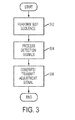
- FIG. 3 illustrates a flow chart describing an exemplary method of controlling a light-emitting device, according to some embodiments
- FIG. 4 is a plan view schematically illustrating an arrangement of light-emitting elements and photodetectors within the light-emitting device shown in FIG. 1 , according to one embodiment
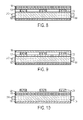
- FIGS. 5-10 are cross-sectional views taken along line V-V of FIG. 4 , illustrating exemplary arrangements of light-emitting elements and photodetectors within the light-emitting device shown in FIG. 1 , according to some embodiments;
- FIG. 11 is a plan view schematically illustrating an arrangement of light-emitting elements and photodetectors within the light-emitting device shown in FIG. 1 , according to another embodiment
- FIGS. 12 and 13 are cross-sectional views taken along line XI-XI of FIG. 11 , illustrating exemplary arrangements of light-emitting elements and photodetectors within the light-emitting device shown in FIG. 1 , according to some embodiments;
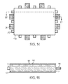
- FIG. 14 is a plan view schematically illustrating an arrangement of light-emitting elements and photodetectors within the light-emitting device shown in FIG. 1 , according to yet another embodiment
- FIGS. 15 and 16 are cross-sectional views taken along line XV-XV of FIG. 14 , illustrating an exemplary arrangement of light-emitting elements and photodetectors within the light-emitting device shown in FIG. 1 , according to some embodiments;
- FIG. 17 is a plan view schematically illustrating an arrangement of light-emitting elements and photodetectors within the light-emitting device shown in FIG. 1 , according to still another embodiment
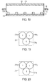
- FIG. 18 is a cross-sectional view taken along line XVIII-XVIII of FIG. 17 , illustrating exemplary arrangements of light-emitting elements and photodetectors within the light-emitting device shown in FIG. 1 , according to one embodiment;
- FIG. 19 is a schematic view illustrating an exemplary photodetector that may be incorporated within the light-emitting device shown in FIG. 1 as part of the control system, according to one embodiment.
- FIG. 20 is a schematic view illustrating an exemplary light-emitting element that may be incorporated within the light-emitting device shown in FIG. 1 , according to one embodiment.
- a light-emitting device 100 may, for example, include a reflector 102, a light guide 104, a diffuser 106 and a prism sheet 108.
- the light-emitting device 100 may also include a plurality of light-emitting elements (not shown).
- the light-emitting device 100 may be used in a display device such as a liquid crystal display (LCD) device. Accordingly, the light-emitting device 100 may be disposed at the rear surface of an LCD panel 110.
- LCD liquid crystal display
- the plurality of light-emitting elements are configured to emit light upon receiving electric current.
- the light-emitting device 100 may further include driving circuitry (not shown) coupled to the plurality of light-emitting elements, which is configured to drive the plurality of light-emitting elements by supplying electric current thereto.
- driving circuitry refers to any type of computer-executable instructions that can be implemented as, for example, hardware, firmware, and/or software.
- the driving circuitry may be provided as a dedicated fixed-purpose circuitry and/or partially or wholly programmable circuitry.
- the light guide 104 may be configured to internally reflect and/or diffuse light emitted by the plurality of light-emitting elements.
- the reflector 102 is disposed on a rear surface of the light guide 104 and has a reflective surface configured to reflect light that would otherwise be transmitted through the rear surface of the light guide 104, back into the light guide 104.
- the reflective surface of the reflector 102 may be configured to reflect light emitted by the plurality of light-emitted elements.
- the reflector 102 may also be disposed on side surfaces of the light guide 104 to reflect light that would otherwise be transmitted through the side surfaces of the light guide 104, back into the light guide 104.
- the diffuser 106 is disposed on a front surface of the light guide 104 and diffuses light transmitted through the front surface of the light guide 104, thereby increasing the uniformity of light emitted by the light-emitting device 100. Because light emitted by the light-emitting elements can be diffused or mixed within the light guide 104 and/or the diffuser 106, the combined structure of the light guide 104 and the diffuser 106 can be referred to as a light-mixing region 100a of the light-emitting device 100.
- the light-mixing region 100a can be generally characterized as being configured to receive light emitted by the plurality of light-emitting elements. It will be appreciated that the diffuser 106 may be omitted from the light emitting device 100 if desired.
- the prism sheet 108 optimizes the angle of light transmitted by the diffuser 106 and ultimately emitted by the light-emitting device 100. It will be appreciated that the prism sheet may be omitted from the light-emitting device 100 if desired.
- the light-emitting device 100 may include additional features and components such as light outcoupling structures, light-scattering structures, brightness-enhancing films, patterned films, or the like, as is known in the art.
- the plurality of light-emitting devices are provided as a plurality of light-emitting diodes (LED).
- LED light-emitting diodes
- the color and brightness of light emitted by an LED changes.
- one or more characteristics e.g., color, color temperature, correlated color temperature, whitepoint, intensity, emittance, brightness, or the like
- characteristics of light emitted by the light-emitting device 100 may change over time.
- LEDs fabricated by different manufacturers, or even the same manufacturer can change at different rates over time. Accordingly, one or more of the aforementioned characteristics of light emitted by the light-emitting device 100 may change at different rates in different locations of the light-emitting device 100.
- the uniformity of one or more characteristics of light emitted by the light-emitting device 100 may deteriorate over time.
- the light-emitting device 100 may further include a control system configured to prevent or reduce the rate of deterioration of characteristics of light emitted by the light-emitting device 100.
- a control system may, for example, include process circuitry 202, test circuitry 204 and a plurality of photodetectors 206.
- the plurality of photodetectors 206 may include n number of photodetectors 206.
- the process circuitry 202 and the test circuitry 204 may be coupled the aforementioned driving circuitry 208 which, in turn, is coupled to a plurality of light-emitting devices 210.
- the plurality of light-emitting elements 210 may include m number of light-emitting elements.
- the plurality of light-emitting elements 210 may be divided into a plurality of groups of light-emitting elements 210, wherein each group of light-emitting elements 210 includes one or more light-emitting elements 210.
- a light-emitting element 210 within a group of light-emitting elements 210 can be driven independently of light-emitting elements 210 within other groups of light-emitting elements 210.
- a plurality of light-emitting elements 210 are driven together.
- the plurality of light-emitting elements 210 within a group of light-emitting elements 210 may be electrically connected together or the driving circuitry 208 may be configured to the plurality of light-emitting elements 210 simultaneously.
- the intensity with which each light-emitting element 210 emits light may be controlled by controlling the amount of current applied to the light-emitting element 210, by controlling the amount of time that a predetermined amount of current is applied to the light emitting element 210 within a time period, or a combination thereof.
- the driving circuitry 208 may be configured to supply electric current that has been amplitude-modulated, pulse width-modulated, or a combination thereof.
- the intensity of light emitted by each of the plurality of light-emitting elements 210 may affect at least one characteristic of light (e.g., color, color temperature, correlated color temperature, whitepoint, intensity, emittance, brightness, or the like) present at a location of the light-mixing region 100a during operation of the light-emitting device.
- the intensity of light emitted by each of the plurality of light-emitting elements 210 may affect at least one of the aforementioned characteristics of light emitted by the light-emitting device 100.
- the plurality of photodetectors 206 may be arranged at a plurality of locations of the light-mixing region 100a.
- the plurality of photodetectors 206 may be configured to detect an intensity of light received at a corresponding plurality of locations of the light-mixing region 100a. Each of the plurality of photodetectors 206 may also be configured to generate a detection signal corresponding to the intensity of the detected light. In one embodiment, the plurality of photodetectors 206 may be sensitive to different colors of light. Accordingly, the plurality of photodetectors 206 may be variously provided as one or more photodetectors sensitive to red light, one or more photodetectors sensitive to green light and one or more photodetectors sensitive to blue light.
- the test circuitry 204 may be configured to perform a test sequence.
- the driving circuitry 208 is controlled to supply electric current to a plurality of groups of light-emitting elements 210 in sequence, wherein each of the plurality of groups of light-emitting elements 210 includes one or more light-emitting elements 210.
- the plurality of groups of light-emitting elements 210 are sequentially driven, only one of the plurality of groups of light-emitting elements 210 emits light at any time.
- the plurality of groups of light-emitting elements 210 can be sequentially driven by the test circuitry 204 periodically, during dimming of the light-emitting elements 210, upon start-up of the light-emitting device, or the like or a combination thereof.
- the plurality of photodetectors 206 detect an intensity of light emitted by individual groups of the plurality of groups of light-emitting elements 210 at a plurality of locations of the light-mixing region 100a. See 302 in FIG. 3 .
- the detection signals generated by each of the plurality ofphotodetectors 206 may be transmitted to the process circuitry 202.
- the process circuitry 202 may be configured to process detection signals generated by the plurality of photodetectors 206. See 304 in FIG. 3 .
- the process circuitry 202 is configured to process detection signals to determine the amount of electric current that should be supplied to each group of light-emitting elements 210 so that at least one of the aforementioned characteristics of light emitted by all of the plurality of light-emitting elements 210 is substantially the same at each of the plurality of locations of the light-mixing region 100a.
- the intensity or flux of light, D, detected by a particular photodetector 206 corresponds to the electric current, I, supplied to a particular group of light-emitting elements 210 multiplied by a coupling coefficient, C, associated with the particular photodetector 206 and the particular group of light-emitting elements 210.
- Values for the C matrix may be obtained upon performing the test sequence. After obtaining values for the C matrix, values for the elements of the D matrix are selected based on a desired color, color temperature, correlated color temperature, whitepoint, intensity, emittance, brightness, or the like or a combination thereof. In one embodiment, values for the elements of the D matrix are selected by choosing the desired brightness level and desired color of the output light from the light-emitting device 100 which will determine red (R), green (G), and blue (B) intensity or flux values to assign to the D elements corresponding to the one or more photodetectors sensitive to red light, the one or more photodetectors sensitive to green light and the one or more photodetectors sensitive to blue light.
- R red
- G green
- B blue
- equation 2 is solved to determine, on a least squares basis, the amount of electric current that needs to be supplied to each of the plurality of groups of light-emitting elements 210 such that at least one characteristic of light emitted by all of the plurality of groups of light-emitting elements 210 is substantially the same at each of the plurality of locations of the light-mixing region 100a.
- the process circuitry 202 generates an adjustment signal to the based on the processing of the detection signals and transmits the adjustment signal to the driving circuitry 208. See 306 in FIG. 3 .
- electric current supplied to the plurality of light-emitting elements 210 by the driving circuitry 208 is adjustable based on the adjustment signal such that at least one characteristic of light emitted by all of the plurality of light-emitting elements 210 is substantially the same at each of the plurality of locations of the light-mixing region 100a.
- the driving circuitry 208 is configured to supply electric current to the plurality of light-emitting elements 210 such that at least one characteristic of light emitted by all of the plurality of light-emitting elements 210 is substantially the same at each of the plurality of locations of the light-mixing region 100a.
- the plurality of photodetectors 206 may be further configured to detect ambient light received at the plurality of locations of the light-mixing region 100a before the test sequence is performed (e.g., when no electric current is supplied to the plurality of light-emitting elements 210). Accordingly, each of the plurality of photodetectors 206 may be configured generate a detection signal corresponding to the intensity of ambient light.
- the process circuitry 202 may further be configured to adjust values of the coupling coefficients in matrix C based on the detection signals generated in response to the ambient light detected, prior to selecting the elements of the D matrix.
- the plurality of photodetectors 210 may be calibrated prior to being used in the control system exemplarily described with respect to FIG. 2 .
- the periphery of the light-mixing region 100a is delineated by a dashed line.
- the plurality of light-emitting elements 210 are arranged outside the periphery of the light-mixing region 100a and the plurality of photodetectors 206 are arranged at a plurality of locations within the periphery of the light-mixing region 100a.
- the plurality of light-emitting elements 210 may be configured to transmit light through side surfaces of the light guide 104 and the plurality of photodetectors 206 may be configured to receive light transmitted through the rear surface of the light guide 104. Accordingly, the plurality of light-emitting elements 210 may be arranged at side surfaces of the light guide 104 and the plurality of photodetectors 206 may be arranged at the rear surface of the light guide 104, below the front surface of the light guide 104, above the reflective surface of the reflector 102.
- the plurality of light-emitting elements 210 may be arranged at side surfaces of the light guide 104 and the plurality of photodetectors 206 may be arranged at the rear surface of the light guide 104.
- the reflector 102 may include a plurality of openings 602 defined therein and the plurality of photodetectors 206 may be disposed within the openings 602.
- the plurality of photodetectors 206 may be disposed within the openings 602 so as to be arranged at the reflective surface of the reflector 102.
- the plurality of photodetectors 206 may be disposed within the openings 602 so as to be arranged above or below the reflective surface of the reflector 102.
- the plurality of light-emitting elements 210 may be arranged at side surfaces of the light guide 104 and the plurality of photodetectors 206 may be arranged at the rear surface of the light guide 104.
- the reflector 102 may include a plurality of partially-transmissive regions 702 defined therein.
- the plurality of partially-transmissive regions 702 may partially transmit light emitted by the light-emitting elements 210.
- the partially-transmissive regions may be formed of at least one material selected from the group consisting of a partially silvered coating, a multilayered dielectric coating on a transmissive film or substrate, or the like or a combination thereof.
- the plurality of photodetectors 206 may be disposed adjacent to corresponding ones of the partially-transmissive regions 702.
- the plurality of light-emitting elements 210 may be arranged at side surfaces of the light guide 104.
- the plurality of photodetectors 206 may be configured to receive light transmitted through the front surface of the light guide 104. Accordingly, the plurality of photodetectors 206 are arranged at the front surface of the light guide 104, above the rear surface of the light guide 104, between the light guide 104 and the diffuser 106.
- the diffuser 106 may include a plurality of openings defined therein, similar to the openings 602 described with respect to FIG. 6 , and the plurality of photodetectors 206 may be disposed within the openings.
- the plurality of light-emitting elements 210 may be arranged at side surfaces of the light guide 104 and the plurality of photodetectors 206 may be arranged at the front surface of the light guide 104.
- the plurality of photodetectors 206 may be disposed between the diffuser 106 and the prism sheet 108.
- the prism sheet 108 may include a plurality of openings defined therein, similar to the openings 602 described with respect to FIG. 6 , and the plurality of photodetectors 206 may be disposed within the openings.
- the plurality of light-emitting elements 210 may be arranged at side surfaces of the light guide 104 and the plurality of photodetectors 206 may be arranged at the front surface of the light guide 104. In the illustrated embodiment, however, the plurality of photodetectors 206 may be disposed on the prism sheet 108.
- the plurality of light-emitting elements 210 and the plurality of photodetectors 206 are arranged at a plurality of locations within the periphery of the light-mixing region 100a.
- the plurality of light-emitting elements 210 may be arranged in an array and the plurality of photodetectors 206 may be disposed between light-emitting elements 210 in the array.
- the plurality of photodetectors 206 may be configured to receive light transmitted through the rear or front surfaces of the light guide 104 as described above with respect to FIGS. 5-10 .
- the plurality of light-emitting elements 210 may be configured to transmit light through the rear surface of the light guide 104. Accordingly, the plurality of light-emitting elements 210 may be arranged at the rear surface of the light guide 104 in the same manner that the plurality of photodetectors 206 are arranged at the rear surface of the light guide 104 as exemplarily described above with respect to FIG. 5 .
- the plurality of light-emitting elements 210 may be disposed within openings formed in the reflector 102, in the same manner that the plurality of photodetectors 206 are disposed within openings 602 as exemplarily described with respect to FIG. 6 . In another embodiment, the plurality of light-emitting elements 210 may be disposed adjacent to partially-transmissive regions formed in the reflector 102, in the same manner that the plurality of photodetectors 206 are disposed adjacent to partially-transmissive regions 702 as exemplarily described with respect to FIG. 7 .
- the light-mixing region 100a may include a light guide 104 and a diffuser 106. In other embodiments, however, the light-mixing region 100a may include a light-mixing cavity instead of a light guide 104.
- a light-mixing cavity 1202 may comprise a space defined between the reflector 102 and the diffuser 106.
- a support may be provided to couple the reflector 102 to the diffuser 106 and define side surfaces 1204 of the light-mixing cavity 1202.
- the side surfaces 1204 of the light-mixing cavity 1202 may comprise a reflective material to enhance the brightness of light emitted by the light-emitting device 100.
- the plurality of light-emitting elements 210 may be disposed at a rear surface of the light-mixing cavity 1202 and the plurality of photodetectors 206 may be configured to receive light transmitted to the rear surface of the light-mixing cavity 1202. Accordingly, the plurality of light-emitting elements 210 may be arranged at the rear surface of the light-mixing cavity 1202 and the plurality of photodetectors 206 may be arranged at the rear surface of the light-mixing cavity 1202, above the reflective surface of the reflector 102.
- the plurality of light-emitting elements 210 may be disposed within openings formed in the reflector 102, in the same manner that the plurality of photodetectors 206 are disposed within openings 602 as exemplarily described with respect to FIG. 6 . In another embodiment, the plurality of light-emitting elements 210 may be disposed adjacent to partially-transmissive regions formed in the reflector 102, in the same manner that the plurality of photodetectors 206 are disposed adjacent to partially-transmissive regions 702 as exemplarily described with respect to FIG. 7 .
- the plurality of photodetectors 206 are disposed at a rear surface of the light-mixing cavity 1202. In other embodiments, however, the plurality of photodetectors 206 may be disposed between the diffuser 106 and the prism sheet 108, or on the prism sheet 108, in the same manner as discussed above with respect to FIGS. 9 and 10 .
- the light-emitting device 100 may be provided in a similar manner as described above with respect to FIG. 12 . As shown in FIG. 13 , however, the diffuser 106 may be omitted. Upon omitting the diffuser 106, the height of the light-mixing cavity 1202 (i.e., the distance from the reflector 102 to the prism sheet 108 may be increased to ensure that light emitted by the plurality of light-emitting elements 210 is sufficiently mixed.
- FIG. 14 is a plan view schematically illustrating an arrangement of light-emitting elements and photodetectors within the light-emitting device shown in FIG. 1 , according to yet another embodiment.
- FIGS. 15 and 16 are cross-sectional views taken along line XV-XV of FIG. 14 , illustrating an exemplary arrangement of light-emitting elements and photodetectors within the light-emitting device shown in FIG. 1 , according to some embodiments.
- the plurality of light-emitting elements 210 are arranged outside the periphery of the light-mixing region 100a.
- the plurality of photodetectors 206 are arranged at a plurality of locations outside the periphery of the light-mixing region 100a.
- the plurality of light-emitting elements 210 may be configured to transmit light through side surfaces of the light guide 104 and the plurality of photodetectors 206 may be configured to receive light transmitted through the side surfaces of the light guide 104. Accordingly, the plurality of light-emitting elements 210 and the plurality of photodetectors 206 may be arranged at side surfaces of the light guide 104.
- the light-emitting device 100 may be provided in a similar manner as exemplarily described above with respect to FIG. 15 .
- the light-mixing region 100a may include a light-mixing cavity 1202 as exemplarily discussed above with respect to FIG. 12 , instead of a light guide 104.
- each of the plurality of light-emitting elements 210 and the plurality of photodetectors 206 may be exposed to the light-mixing cavity 1202 via a corresponding opening or partially-transmissive region formed in a side surface 1204, in a manner similar to that described above with respect to FIGS. 6 and 7 .
- each of the plurality of light-emitting elements 210 and the plurality of photodetectors 206 may extend into the light-mixing cavity 1202 through a corresponding opening formed in a side surface 1204.
- the plurality of photodetectors 206 are arranged at a plurality of locations outside a periphery of the light-mixing region 100a and the plurality of light-emitting elements 210 are arranged within the periphery of the light-mixing region 100a.
- the light-emitting device 100 may be provided in a similar manner as exemplarily described above with respect to FIG. 12 .
- each of the plurality of photodetectors 206 may be exposed to the light-mixing cavity 1202 via a corresponding opening or partially transmissive region formed in the side surfaces 1204, in a manner similar to that described above with respect to FIGS. 16 .
- each of the plurality of light-emitting elements 210 and the plurality of photodetectors 206 may extend into the light-mixing cavity 1202 via a corresponding opening formed in the side surfaces 1204.
- the plurality of photodetectors 206 have been described above with respect to FIGS. 4-18 as being arranged either at a plurality of locations outside the periphery of the light-mixing region 100a or at a plurality of locations within the periphery of the light-mixing region 100a, it will be appreciated that the plurality of photodetectors 206 can be arranged at one or more locations outside the periphery of the light-mixing region 100a and at one or more locations within the periphery of the light-mixing region 100a.
- the plurality of light-emitting elements 210 have been described above with respect to FIGS.
- the plurality of light-emitting elements 210 can be arranged outside the periphery and within the periphery of the light-mixing region 100a.
- the plurality of photodetectors 206 have been described as being arranged at the rear surface of the light guide 104 (e.g., as shown in FIGS. 5-7 ) or at the front surface of the light guide 104 (e.g., as shown in FIGS.
- one or more the plurality of photodetectors 206 can be arranged at the rear surface of the light guide 104 and one or more of the plurality of photodetectors 206 can be arranged at the front surface of the light guide 104.
- plurality of light-emitting elements 210 have been described above with respect to FIGS. 4-10 and 14-16 as being arranged outside the periphery of the light-mixing region 100a along all of the sides of the light-mixing region 100a, it will be appreciated that plurality of light-emitting elements 210 may be arranged outside the periphery of the light-mixing region 100a along only one of the sides of the light-mixing region 100a. It will also be appreciated that the plurality of light-emitting elements 210 may be arranged outside the periphery of the light-mixing region 100a along any number of the sides of the light-mixing region 100a. In the embodiments exemplarily described above with respect to FIGS.
- the plurality of light-emitting elements 210 are spaced apart from each other at substantially uniform intervals along a side of the light-mixing region 100a. It will be appreciated, however, that the plurality of light-emitting elements 210 may be spaced apart from each other at irregular intervals along at least one side of the light-mixing region 100a. Further, in the embodiments exemplarily described above with respect to FIGS. 11-13 , 17 and 18 , the plurality of light-emitting elements 210 are spaced apart from each other at substantially uniform intervals within the periphery of the light-mixing region 100a. It will be appreciated, however, that the plurality of light-emitting elements 210 may be spaced apart from each other at irregular intervals within the periphery of the light-mixing region 100a.
- plurality of photodetectors 206 have been described above with respect to FIGS. 14-18 as being arranged outside the periphery of the light-mixing region 100a along all of the sides of the light-mixing region 100a, it will be appreciated that plurality of photodetectors 206 may be arranged outside the periphery of the light-mixing region 100a along only one of the sides of the light-mixing region 100a. It will also be appreciated that the plurality of photodetectors 206 may be arranged outside the periphery of the light-mixing region 100a along any number of the sides of the light-mixing region 100a. In the embodiments exemplarily described above with respect to FIGS.
- the plurality of photodetectors 206 are spaced apart from each other at substantially uniform intervals along a side of the light-mixing region 100a. It will be appreciated, however, that the plurality of photodetectors 206 may be spaced apart from each other at irregular intervals along at least one side of the light-mixing region 100a. Further, in the embodiments exemplarily described above with respect to FIGS. 4-13 , the plurality of photodetectors 206 are spaced apart from each other at substantially uniform intervals within the periphery of the light-mixing region 100a. It will be appreciated, however, that the plurality of photodetectors 206 may be spaced apart from each other at irregular intervals within the periphery of the light-mixing region 100a.
- the plurality of photodetectors 206 may be divided into a plurality of groups of photodetectors, wherein photodetectors within a group of photodetectors are closer to each other than photodetectors of another group.
- Each photodetector in a group includes a photodiode having a light-receiving region coupled to a color filter configured to transmit light having a predetermined wavelength (or wavelength range) to the light-receiving region.
- each photodetector may be sensitive to light having the predetermined wavelength (or wavelength range) due to the presence of the color filter.
- each photodetector within a group of photodetectors is sensitive to light having a different wavelength (or wavelength range) than another photodetector within the group of photodetectors.
- each group of photodetectors 206 may include a red photodetector 206 R , a green photodetector 206 G and a blue photodetector 206 B .
- the red photodetector 206 R may include a photodiode having a light-receiving region coupled to a red color filter. Accordingly, the red photodetector 206 R may be sensitive to red light.
- the green photodetector 206 G may include a photodiode having a light-receiving region coupled to a green color filter. Accordingly, the green photodetector 206 G may be sensitive to green light.
- the blue photodetector 206 B may include a photodiode having a light-receiving region coupled to a blue color filter. Accordingly, the blue photodetector 206 B may be sensitive to blue light.
- the color filters may be provided as colorimetric (color matching function (CMF) based filters.
- each of the plurality of light-emitting elements 210 may be provided as an individual LED (e.g., a white LED, a red LED, a green LED, a blue LED, an amber LED, or the like).
- the colors identified above are merely exemplary and that LEDs capable of emitting any color (e.g., a color having a wavelength range between wavelengths of red and amber, a color having a wavelength range between wavelengths of amber and green, a color having a wavelength range between wavelengths of green and blue, violet, or the like) may be incorporated within the light-emitting device shown in Fig. 1 .
- the light-emitting elements may also be phosphor converted LEDs.
- the plurality of light-emitting elements 210 emits light having a different wavelength range than another of the plurality of light-emitting elements 210.
- the plurality of light-emitting elements 210 may be divided into a plurality of groups of LEDs, wherein each LED in the group includes an LED configured to emit light having a predetermined wavelength (or wavelength range).
- each group of LEDs 210 may include a red LED 210R, a green LED 210G and a blue LED 210B.
Landscapes
- Planar Illumination Modules (AREA)
- Led Devices (AREA)
- Led Device Packages (AREA)
- Arrangement Of Elements, Cooling, Sealing, Or The Like Of Lighting Devices (AREA)
- Circuit Arrangement For Electric Light Sources In General (AREA)
Applications Claiming Priority (1)
| Application Number | Priority Date | Filing Date | Title |
|---|---|---|---|
| US12/334,269 US8143791B2 (en) | 2008-12-12 | 2008-12-12 | Control system for light-emitting device |
Publications (3)
| Publication Number | Publication Date |
|---|---|
| EP2197241A2 true EP2197241A2 (de) | 2010-06-16 |
| EP2197241A3 EP2197241A3 (de) | 2011-11-30 |
| EP2197241B1 EP2197241B1 (de) | 2016-11-02 |
Family
ID=42111227
Family Applications (1)
| Application Number | Title | Priority Date | Filing Date |
|---|---|---|---|
| EP09178306.8A Not-in-force EP2197241B1 (de) | 2008-12-12 | 2009-12-08 | Steuersystem für lichtemittierende Vorrichtungen |
Country Status (3)
| Country | Link |
|---|---|
| US (1) | US8143791B2 (de) |
| EP (1) | EP2197241B1 (de) |
| JP (1) | JP2010141336A (de) |
Cited By (1)
| Publication number | Priority date | Publication date | Assignee | Title |
|---|---|---|---|---|
| EP2795380A1 (de) * | 2011-12-22 | 2014-10-29 | 3M Innovative Properties Company | Optische vorrichtung mit sensor und verfahren zu ihrer herstellung und verwendung |
Families Citing this family (4)
| Publication number | Priority date | Publication date | Assignee | Title |
|---|---|---|---|---|
| US20100245279A1 (en) * | 2009-03-31 | 2010-09-30 | Robe Lighting S.R.O. | Display and display control system for an automated luminaire |
| US20120217881A1 (en) * | 2011-02-28 | 2012-08-30 | Qualcomm Mems Technologies, Inc. | Illumination systems with natural and artificial light inputs |
| US20150160305A1 (en) * | 2013-12-11 | 2015-06-11 | General Electric Company | Method of testing a dimming lighting system |
| US12482797B2 (en) * | 2021-09-30 | 2025-11-25 | Hefei BOE Ruisheng Technology Co., Ltd. | Light-emitting substrate, backlight module and display device |
Family Cites Families (18)
| Publication number | Priority date | Publication date | Assignee | Title |
|---|---|---|---|---|
| US6448550B1 (en) * | 2000-04-27 | 2002-09-10 | Agilent Technologies, Inc. | Method and apparatus for measuring spectral content of LED light source and control thereof |
| US6630801B2 (en) * | 2001-10-22 | 2003-10-07 | Lümileds USA | Method and apparatus for sensing the color point of an RGB LED white luminary using photodiodes |
| US6753661B2 (en) * | 2002-06-17 | 2004-06-22 | Koninklijke Philips Electronics N.V. | LED-based white-light backlighting for electronic displays |
| WO2006006537A1 (ja) * | 2004-07-12 | 2006-01-19 | Sony Corporation | バックライトユニットの駆動装置及びその駆動方法 |
| US7324080B1 (en) * | 2004-12-03 | 2008-01-29 | Sysview Technology, Inc. | Backlighting in liquid crystal flat panel display |
| JP2006278368A (ja) * | 2005-03-28 | 2006-10-12 | Sony Corp | 光源装置および表示装置 |
| DE102005020568A1 (de) * | 2005-04-30 | 2006-11-09 | Osram Opto Semiconductors Gmbh | Lichtquellenanordnung zur Hinterleuchtung von Anzeigevorrichtungen sowie Anzeigevorrichtung |
| US20100148675A1 (en) * | 2005-06-30 | 2010-06-17 | Koninklijke Philips Electronics, N.V. | Method and system for controlling the output of a luminaire |
| JP3872810B1 (ja) * | 2005-08-12 | 2007-01-24 | シャープ株式会社 | 光源制御装置、照明装置及び液晶表示装置 |
| US7804260B2 (en) * | 2005-10-26 | 2010-09-28 | Koninklijke Philips Electronics N.V. | LED luminary system |
| JP2007317849A (ja) * | 2006-05-25 | 2007-12-06 | Sharp Corp | バックライト装置およびバックライト制御方法 |
| US7696964B2 (en) * | 2006-06-09 | 2010-04-13 | Philips Lumileds Lighting Company, Llc | LED backlight for LCD with color uniformity recalibration over lifetime |
| CN101427174A (zh) * | 2006-06-19 | 2009-05-06 | 夏普株式会社 | 显示装置用照明装置及其控制电路 |
| US7959341B2 (en) * | 2006-07-20 | 2011-06-14 | Rambus International Ltd. | LED color management and display systems |
| JP2008140756A (ja) * | 2006-11-02 | 2008-06-19 | Harison Toshiba Lighting Corp | バックライト装置 |
| JP4803069B2 (ja) * | 2007-02-23 | 2011-10-26 | ソニー株式会社 | 光源装置および液晶表示装置 |
| JP2008268642A (ja) * | 2007-04-23 | 2008-11-06 | Sony Corp | バックライト装置、バックライト制御方法、および液晶表示装置 |
| JP4395801B2 (ja) * | 2007-11-13 | 2010-01-13 | ソニー株式会社 | 面状光源装置及び液晶表示装置組立体 |
-
2008
- 2008-12-12 US US12/334,269 patent/US8143791B2/en not_active Expired - Fee Related
-
2009
- 2009-12-08 EP EP09178306.8A patent/EP2197241B1/de not_active Not-in-force
- 2009-12-10 JP JP2009280691A patent/JP2010141336A/ja active Pending
Cited By (1)
| Publication number | Priority date | Publication date | Assignee | Title |
|---|---|---|---|---|
| EP2795380A1 (de) * | 2011-12-22 | 2014-10-29 | 3M Innovative Properties Company | Optische vorrichtung mit sensor und verfahren zu ihrer herstellung und verwendung |
Also Published As
| Publication number | Publication date |
|---|---|
| JP2010141336A (ja) | 2010-06-24 |
| US20100148693A1 (en) | 2010-06-17 |
| EP2197241B1 (de) | 2016-11-02 |
| EP2197241A3 (de) | 2011-11-30 |
| US8143791B2 (en) | 2012-03-27 |
Similar Documents
| Publication | Publication Date | Title |
|---|---|---|
| CN100435004C (zh) | 面状光源装置以及使用其的显示装置 | |
| US7474294B2 (en) | Use of a plurality of light sensors to regulate a direct-firing backlight for a display | |
| KR101460005B1 (ko) | 포토센서 도광체를 가지는 광원 | |
| US8596816B2 (en) | Multi-die LED package and backlight unit using the same | |
| CN100456354C (zh) | 光源驱动装置、光源系统以及改善光源均匀发光的方法 | |
| US7656398B2 (en) | Surface light source device and liquid crystal display device | |
| US7294816B2 (en) | LED illumination system having an intensity monitoring system | |
| EP1794811B1 (de) | Beleuchtungssystem | |
| JP4371733B2 (ja) | 面状光源装置 | |
| US20120104954A1 (en) | Method and system for adjusting light output from a light source | |
| US20100007600A1 (en) | Method for light emitting diode control and corresponding light sensor array, backlight and liquid crystal display | |
| EP2197241B1 (de) | Steuersystem für lichtemittierende Vorrichtungen | |
| US7560876B2 (en) | Light device and control method thereof | |
| KR20040053750A (ko) | 광원 장치 및 표시 장치 | |
| US8215818B2 (en) | LED light box with photodetector control | |
| CN101925775B (zh) | 照明装置和显示装置 | |
| US7619192B2 (en) | Direct backlight module using optical feedback | |
| KR20070003690A (ko) | 조명 시스템, 조명 디스플레이 장치 및 조명 제공 방법 | |
| JPH11260568A (ja) | 照明装置 | |
| US20080100563A1 (en) | Light Device and Control Method Thereof | |
| US7473879B2 (en) | LED illumination system having an intensity monitoring system | |
| JP2006310307A (ja) | Lcdバックライトディスプレイの光源 | |
| KR20080045130A (ko) | 컬러 포인트 제어 시스템 | |
| JP5052298B2 (ja) | 面状光源装置および表示装置 | |
| JP2013511828A (ja) | 発光デバイス |
Legal Events
| Date | Code | Title | Description |
|---|---|---|---|
| PUAI | Public reference made under article 153(3) epc to a published international application that has entered the european phase |
Free format text: ORIGINAL CODE: 0009012 |
|
| AK | Designated contracting states |
Kind code of ref document: A2 Designated state(s): AT BE BG CH CY CZ DE DK EE ES FI FR GB GR HR HU IE IS IT LI LT LU LV MC MK MT NL NO PL PT RO SE SI SK SM TR |
|
| AX | Request for extension of the european patent |
Extension state: AL BA RS |
|
| PUAL | Search report despatched |
Free format text: ORIGINAL CODE: 0009013 |
|
| AK | Designated contracting states |
Kind code of ref document: A3 Designated state(s): AT BE BG CH CY CZ DE DK EE ES FI FR GB GR HR HU IE IS IT LI LT LU LV MC MK MT NL NO PL PT RO SE SI SK SM TR |
|
| AX | Request for extension of the european patent |
Extension state: AL BA RS |
|
| RIC1 | Information provided on ipc code assigned before grant |
Ipc: H05B 33/08 20060101AFI20111026BHEP Ipc: F21S 8/00 20060101ALI20111026BHEP |
|
| 17P | Request for examination filed |
Effective date: 20120530 |
|
| 17Q | First examination report despatched |
Effective date: 20130311 |
|
| GRAP | Despatch of communication of intention to grant a patent |
Free format text: ORIGINAL CODE: EPIDOSNIGR1 |
|
| RIC1 | Information provided on ipc code assigned before grant |
Ipc: H05B 33/08 20060101AFI20160627BHEP |
|
| INTG | Intention to grant announced |
Effective date: 20160714 |
|
| GRAS | Grant fee paid |
Free format text: ORIGINAL CODE: EPIDOSNIGR3 |
|
| GRAA | (expected) grant |
Free format text: ORIGINAL CODE: 0009210 |
|
| AK | Designated contracting states |
Kind code of ref document: B1 Designated state(s): AT BE BG CH CY CZ DE DK EE ES FI FR GB GR HR HU IE IS IT LI LT LU LV MC MK MT NL NO PL PT RO SE SI SK SM TR |
|
| REG | Reference to a national code |
Ref country code: GB Ref legal event code: FG4D |
|
| REG | Reference to a national code |
Ref country code: AT Ref legal event code: REF Ref document number: 842983 Country of ref document: AT Kind code of ref document: T Effective date: 20161115 Ref country code: CH Ref legal event code: EP |
|
| REG | Reference to a national code |
Ref country code: IE Ref legal event code: FG4D |
|
| REG | Reference to a national code |
Ref country code: DE Ref legal event code: R096 Ref document number: 602009042053 Country of ref document: DE |
|
| REG | Reference to a national code |
Ref country code: FR Ref legal event code: PLFP Year of fee payment: 8 |
|
| PG25 | Lapsed in a contracting state [announced via postgrant information from national office to epo] |
Ref country code: LV Free format text: LAPSE BECAUSE OF FAILURE TO SUBMIT A TRANSLATION OF THE DESCRIPTION OR TO PAY THE FEE WITHIN THE PRESCRIBED TIME-LIMIT Effective date: 20161102 |
|
| REG | Reference to a national code |
Ref country code: NL Ref legal event code: MP Effective date: 20161102 |
|
| REG | Reference to a national code |
Ref country code: LT Ref legal event code: MG4D |
|
| REG | Reference to a national code |
Ref country code: AT Ref legal event code: MK05 Ref document number: 842983 Country of ref document: AT Kind code of ref document: T Effective date: 20161102 |
|
| PG25 | Lapsed in a contracting state [announced via postgrant information from national office to epo] |
Ref country code: NL Free format text: LAPSE BECAUSE OF FAILURE TO SUBMIT A TRANSLATION OF THE DESCRIPTION OR TO PAY THE FEE WITHIN THE PRESCRIBED TIME-LIMIT Effective date: 20161102 Ref country code: GR Free format text: LAPSE BECAUSE OF FAILURE TO SUBMIT A TRANSLATION OF THE DESCRIPTION OR TO PAY THE FEE WITHIN THE PRESCRIBED TIME-LIMIT Effective date: 20170203 Ref country code: NO Free format text: LAPSE BECAUSE OF FAILURE TO SUBMIT A TRANSLATION OF THE DESCRIPTION OR TO PAY THE FEE WITHIN THE PRESCRIBED TIME-LIMIT Effective date: 20170202 Ref country code: SE Free format text: LAPSE BECAUSE OF FAILURE TO SUBMIT A TRANSLATION OF THE DESCRIPTION OR TO PAY THE FEE WITHIN THE PRESCRIBED TIME-LIMIT Effective date: 20161102 Ref country code: LT Free format text: LAPSE BECAUSE OF FAILURE TO SUBMIT A TRANSLATION OF THE DESCRIPTION OR TO PAY THE FEE WITHIN THE PRESCRIBED TIME-LIMIT Effective date: 20161102 |
|
| PG25 | Lapsed in a contracting state [announced via postgrant information from national office to epo] |
Ref country code: PL Free format text: LAPSE BECAUSE OF FAILURE TO SUBMIT A TRANSLATION OF THE DESCRIPTION OR TO PAY THE FEE WITHIN THE PRESCRIBED TIME-LIMIT Effective date: 20161102 Ref country code: IS Free format text: LAPSE BECAUSE OF FAILURE TO SUBMIT A TRANSLATION OF THE DESCRIPTION OR TO PAY THE FEE WITHIN THE PRESCRIBED TIME-LIMIT Effective date: 20170302 Ref country code: HR Free format text: LAPSE BECAUSE OF FAILURE TO SUBMIT A TRANSLATION OF THE DESCRIPTION OR TO PAY THE FEE WITHIN THE PRESCRIBED TIME-LIMIT Effective date: 20161102 Ref country code: PT Free format text: LAPSE BECAUSE OF FAILURE TO SUBMIT A TRANSLATION OF THE DESCRIPTION OR TO PAY THE FEE WITHIN THE PRESCRIBED TIME-LIMIT Effective date: 20170302 Ref country code: AT Free format text: LAPSE BECAUSE OF FAILURE TO SUBMIT A TRANSLATION OF THE DESCRIPTION OR TO PAY THE FEE WITHIN THE PRESCRIBED TIME-LIMIT Effective date: 20161102 Ref country code: FI Free format text: LAPSE BECAUSE OF FAILURE TO SUBMIT A TRANSLATION OF THE DESCRIPTION OR TO PAY THE FEE WITHIN THE PRESCRIBED TIME-LIMIT Effective date: 20161102 Ref country code: ES Free format text: LAPSE BECAUSE OF FAILURE TO SUBMIT A TRANSLATION OF THE DESCRIPTION OR TO PAY THE FEE WITHIN THE PRESCRIBED TIME-LIMIT Effective date: 20161102 Ref country code: BE Free format text: LAPSE BECAUSE OF NON-PAYMENT OF DUE FEES Effective date: 20161231 |
|
| PG25 | Lapsed in a contracting state [announced via postgrant information from national office to epo] |
Ref country code: DK Free format text: LAPSE BECAUSE OF FAILURE TO SUBMIT A TRANSLATION OF THE DESCRIPTION OR TO PAY THE FEE WITHIN THE PRESCRIBED TIME-LIMIT Effective date: 20161102 Ref country code: RO Free format text: LAPSE BECAUSE OF FAILURE TO SUBMIT A TRANSLATION OF THE DESCRIPTION OR TO PAY THE FEE WITHIN THE PRESCRIBED TIME-LIMIT Effective date: 20161102 Ref country code: SK Free format text: LAPSE BECAUSE OF FAILURE TO SUBMIT A TRANSLATION OF THE DESCRIPTION OR TO PAY THE FEE WITHIN THE PRESCRIBED TIME-LIMIT Effective date: 20161102 Ref country code: EE Free format text: LAPSE BECAUSE OF FAILURE TO SUBMIT A TRANSLATION OF THE DESCRIPTION OR TO PAY THE FEE WITHIN THE PRESCRIBED TIME-LIMIT Effective date: 20161102 Ref country code: CZ Free format text: LAPSE BECAUSE OF FAILURE TO SUBMIT A TRANSLATION OF THE DESCRIPTION OR TO PAY THE FEE WITHIN THE PRESCRIBED TIME-LIMIT Effective date: 20161102 |
|
| REG | Reference to a national code |
Ref country code: CH Ref legal event code: PL |
|
| REG | Reference to a national code |
Ref country code: DE Ref legal event code: R097 Ref document number: 602009042053 Country of ref document: DE |
|
| PG25 | Lapsed in a contracting state [announced via postgrant information from national office to epo] |
Ref country code: SM Free format text: LAPSE BECAUSE OF FAILURE TO SUBMIT A TRANSLATION OF THE DESCRIPTION OR TO PAY THE FEE WITHIN THE PRESCRIBED TIME-LIMIT Effective date: 20161102 Ref country code: BE Free format text: LAPSE BECAUSE OF FAILURE TO SUBMIT A TRANSLATION OF THE DESCRIPTION OR TO PAY THE FEE WITHIN THE PRESCRIBED TIME-LIMIT Effective date: 20161102 Ref country code: BG Free format text: LAPSE BECAUSE OF FAILURE TO SUBMIT A TRANSLATION OF THE DESCRIPTION OR TO PAY THE FEE WITHIN THE PRESCRIBED TIME-LIMIT Effective date: 20170202 Ref country code: IT Free format text: LAPSE BECAUSE OF FAILURE TO SUBMIT A TRANSLATION OF THE DESCRIPTION OR TO PAY THE FEE WITHIN THE PRESCRIBED TIME-LIMIT Effective date: 20161102 |
|
| PLBE | No opposition filed within time limit |
Free format text: ORIGINAL CODE: 0009261 |
|
| STAA | Information on the status of an ep patent application or granted ep patent |
Free format text: STATUS: NO OPPOSITION FILED WITHIN TIME LIMIT |
|
| PG25 | Lapsed in a contracting state [announced via postgrant information from national office to epo] |
Ref country code: MC Free format text: LAPSE BECAUSE OF FAILURE TO SUBMIT A TRANSLATION OF THE DESCRIPTION OR TO PAY THE FEE WITHIN THE PRESCRIBED TIME-LIMIT Effective date: 20161102 |
|
| REG | Reference to a national code |
Ref country code: IE Ref legal event code: MM4A |
|
| 26N | No opposition filed |
Effective date: 20170803 |
|
| PG25 | Lapsed in a contracting state [announced via postgrant information from national office to epo] |
Ref country code: CH Free format text: LAPSE BECAUSE OF NON-PAYMENT OF DUE FEES Effective date: 20161231 Ref country code: LI Free format text: LAPSE BECAUSE OF NON-PAYMENT OF DUE FEES Effective date: 20161231 Ref country code: LU Free format text: LAPSE BECAUSE OF NON-PAYMENT OF DUE FEES Effective date: 20161208 |
|
| REG | Reference to a national code |
Ref country code: FR Ref legal event code: PLFP Year of fee payment: 9 |
|
| PG25 | Lapsed in a contracting state [announced via postgrant information from national office to epo] |
Ref country code: SI Free format text: LAPSE BECAUSE OF FAILURE TO SUBMIT A TRANSLATION OF THE DESCRIPTION OR TO PAY THE FEE WITHIN THE PRESCRIBED TIME-LIMIT Effective date: 20161102 Ref country code: IE Free format text: LAPSE BECAUSE OF NON-PAYMENT OF DUE FEES Effective date: 20161208 |
|
| PG25 | Lapsed in a contracting state [announced via postgrant information from national office to epo] |
Ref country code: HU Free format text: LAPSE BECAUSE OF FAILURE TO SUBMIT A TRANSLATION OF THE DESCRIPTION OR TO PAY THE FEE WITHIN THE PRESCRIBED TIME-LIMIT; INVALID AB INITIO Effective date: 20091208 Ref country code: CY Free format text: LAPSE BECAUSE OF FAILURE TO SUBMIT A TRANSLATION OF THE DESCRIPTION OR TO PAY THE FEE WITHIN THE PRESCRIBED TIME-LIMIT Effective date: 20161102 |
|
| PG25 | Lapsed in a contracting state [announced via postgrant information from national office to epo] |
Ref country code: MK Free format text: LAPSE BECAUSE OF FAILURE TO SUBMIT A TRANSLATION OF THE DESCRIPTION OR TO PAY THE FEE WITHIN THE PRESCRIBED TIME-LIMIT Effective date: 20161102 Ref country code: TR Free format text: LAPSE BECAUSE OF FAILURE TO SUBMIT A TRANSLATION OF THE DESCRIPTION OR TO PAY THE FEE WITHIN THE PRESCRIBED TIME-LIMIT Effective date: 20161102 |
|
| PG25 | Lapsed in a contracting state [announced via postgrant information from national office to epo] |
Ref country code: MT Free format text: LAPSE BECAUSE OF NON-PAYMENT OF DUE FEES Effective date: 20161208 |
|
| PGFP | Annual fee paid to national office [announced via postgrant information from national office to epo] |
Ref country code: DE Payment date: 20181126 Year of fee payment: 10 |
|
| PGFP | Annual fee paid to national office [announced via postgrant information from national office to epo] |
Ref country code: FR Payment date: 20181127 Year of fee payment: 10 Ref country code: GB Payment date: 20181127 Year of fee payment: 10 |
|
| REG | Reference to a national code |
Ref country code: DE Ref legal event code: R079 Ref document number: 602009042053 Country of ref document: DE Free format text: PREVIOUS MAIN CLASS: H05B0033080000 Ipc: H05B0045000000 |
|
| REG | Reference to a national code |
Ref country code: DE Ref legal event code: R119 Ref document number: 602009042053 Country of ref document: DE |
|
| GBPC | Gb: european patent ceased through non-payment of renewal fee |
Effective date: 20191208 |
|
| PG25 | Lapsed in a contracting state [announced via postgrant information from national office to epo] |
Ref country code: GB Free format text: LAPSE BECAUSE OF NON-PAYMENT OF DUE FEES Effective date: 20191208 Ref country code: FR Free format text: LAPSE BECAUSE OF NON-PAYMENT OF DUE FEES Effective date: 20191231 Ref country code: DE Free format text: LAPSE BECAUSE OF NON-PAYMENT OF DUE FEES Effective date: 20200701 |