EP2197265B1 - Rohrförmiges element und verfahren zu seiner herstellung - Google Patents
Rohrförmiges element und verfahren zu seiner herstellung Download PDFInfo
- Publication number
- EP2197265B1 EP2197265B1 EP08837086.1A EP08837086A EP2197265B1 EP 2197265 B1 EP2197265 B1 EP 2197265B1 EP 08837086 A EP08837086 A EP 08837086A EP 2197265 B1 EP2197265 B1 EP 2197265B1
- Authority
- EP
- European Patent Office
- Prior art keywords
- material portion
- tubular element
- milk
- additional material
- additional
- Prior art date
- Legal status (The legal status is an assumption and is not a legal conclusion. Google has not performed a legal analysis and makes no representation as to the accuracy of the status listed.)
- Not-in-force
Links
- 238000000034 method Methods 0.000 title claims description 26
- 238000004519 manufacturing process Methods 0.000 title claims description 5
- 239000000463 material Substances 0.000 claims description 175
- 239000008267 milk Substances 0.000 claims description 95
- 210000004080 milk Anatomy 0.000 claims description 95
- 235000013336 milk Nutrition 0.000 claims description 95
- 238000000465 moulding Methods 0.000 claims description 14
- 238000011144 upstream manufacturing Methods 0.000 claims description 9
- 230000007704 transition Effects 0.000 claims description 6
- 101100327917 Caenorhabditis elegans chup-1 gene Proteins 0.000 description 10
- 239000002245 particle Substances 0.000 description 7
- 230000010349 pulsation Effects 0.000 description 6
- 241000894006 Bacteria Species 0.000 description 4
- 241001465754 Metazoa Species 0.000 description 3
- 210000000078 claw Anatomy 0.000 description 3
- 239000004033 plastic Substances 0.000 description 3
- 230000005484 gravity Effects 0.000 description 2
- 229920001296 polysiloxane Polymers 0.000 description 2
- 238000005452 bending Methods 0.000 description 1
- 238000010276 construction Methods 0.000 description 1
- 230000007423 decrease Effects 0.000 description 1
- 230000003247 decreasing effect Effects 0.000 description 1
- 230000000149 penetrating effect Effects 0.000 description 1
- 238000007789 sealing Methods 0.000 description 1
- 239000002210 silicon-based material Substances 0.000 description 1
Images

Classifications
-
- A—HUMAN NECESSITIES
- A01—AGRICULTURE; FORESTRY; ANIMAL HUSBANDRY; HUNTING; TRAPPING; FISHING
- A01J—MANUFACTURE OF DAIRY PRODUCTS
- A01J5/00—Milking machines or devices
- A01J5/04—Milking machines or devices with pneumatic manipulation of teats
- A01J5/044—Milk lines or coupling devices for milk conduits
-
- A—HUMAN NECESSITIES
- A01—AGRICULTURE; FORESTRY; ANIMAL HUSBANDRY; HUNTING; TRAPPING; FISHING
- A01J—MANUFACTURE OF DAIRY PRODUCTS
- A01J5/00—Milking machines or devices
- A01J5/04—Milking machines or devices with pneumatic manipulation of teats
- A01J5/08—Teat-cups with two chambers
Definitions
- the present invention relates to a tubular element and a method for manufacturing thereof.
- the tubular element has an inner space forming a passage for conducting milk, wherein the tubular element constitutes a first material portion which contains the main part of the tubular element and an additional material portion which includes a vent passage adapted to supply air to the inner space of the tubular element and wherein the first material portion and the additional material portion are arranged in contact with each other in a contact area.
- a cluster for milking of animals comprises several teat cups and a corresponding number of short milk tubes each connected to a teat cup.
- Each teat cup includes a liner and a rigid shell forming a pulsation chamber.
- the liner and the short milk tube define a milk passage for conducting milk from a teat to a claw of the cluster.
- a substantially constant vacuum is applied to the milk passage at the same time as a pulsating vacuum is transferred to the pulsation chamber.
- the liner expands and causes a pressure drop in the upper part of the milk passage. If at the same time an abundant flow of milk is present in the milk passage, there is risk that milk will be sucked backwards in the milk passage to the teat. Such a backflow of milk is undesired by several reasons.
- US 6,055,931 shows an air vent plug adapted to be inserted through a hole in a wall of a milk tube.
- the air vent plug has an outer flange engaging an outer surface of the milk tube, a barrel extending through the wall of the milk tube, a tip portion engaging an inner surface of the milk tube and a vent passage extending through the vent plug.
- the vent passage is dimensioned to allow supply of air into the milk passage of the milk tube.
- the existence of the vent plug eliminates the risk of back flow of milk in the milk passage.
- the outer flange of the vent plug projects out from the outer surface of the milk tube and the tip portion projects into the milk passage. This parts of the vent plug provides spaces and corners in the vicinity of the vent passage in which dirt and milk residues can be caught. It is a risk that colonies of bacteria can be grown in such spaces and corners.
- GB644168 shows a device buttoned into a hole of the mouthpiece of a liner which is provided with an aperture permitting of a limited admission of air to the space within the mouthpiece.
- the object of the present invention is to provide a tubular element for conducting milk having a construction such that back flow of milk in the tubular element is prevented and at the same time as the tubular element is very hygienic to use.
- the tubular element is provided with a vent passage, the problem with backflow is eliminated.
- the additional material portion and the vent passage as an integrated part of the first material portion, it is not possible to release the additional material portion and the vent passage from the first material portion without destroying the tubular element. Consequently, the tubular element is sold and mounted as a one-piece unit. Since the material parts of the tubular element are fixedly connected, no further parts need to be used for holding the material portions in a connected state. Thus, the additional material portion can be given a simple design. The material portions are fixedly connected to each other in the whole contact area by means of a homogeneous connection.
- the contact area can provide a tight sealing between the material portions which is completely free from irregularities and concavities. Thus, it does not exist any spaces in the contact area in which dirt, particles and bacteria can be caught. Consequently, the tubular element is very hygienic.
- the first material portion and the additional material portion are moulded together in the contact area.
- the material parts are moulded together by a moulding process called co-moulding.
- co-moulding the material portions are injected in sequence which makes it possible to mould one material portion on a previously moulded material portion.
- an outer surface of the tubular element which is adapted to be in contact with a surrounding, is formed by an outer surface of the first material portion and an outer surface of the additional material portion, wherein the outer surfaces are arranged in relation to each other such that they form a smooth transition between each other at an outer part of the contact area.
- the outer surface of the tubular element does not have any spaces or corners in this area in which dirt and particles can be caught.
- the inner space of the tubular element is defined by an inner surface of the first material portion and an inner surface of the additional material portion, wherein the inner surfaces are arranged in relation to each other such that they form a smooth transition between each other at an inner part of the contact area.
- the inner surface of the tubular element does not either have any spaces or corners in which milk residues can be caught.
- the first material portion and the additional material portion is made of different materials.
- a co-moulding process makes it possible to produce a one-piece tubular element of different materials.
- the additional material portion may be a relatively stiff plastic material. Thereby, the shape of the vent passage in the additional material portion will be maintained even if the tubular element is subjected to bending forces.
- the material in the first material portion may be a material normally used in short milk tubes and liners. Such a material may be a rubber material, a PVC material, a TPE material or a silicone material.
- the tubular element may have at least one curved section.
- the tubular element may be manufactured of a material having a stiffness such that the tubular element has a predetermined shape in an unloaded state.
- Such a tubular element can be provided with a curved section.
- the inner space of the tubular element may have a larger cross section area in the curved section than in an adjacent section. With such a design of the curved section, the flow resistance in the curved section is reduced which facilitates the milk flow through the tubular element.
- the additional material portion may be positioned such that the vent passage is located upstream the curved section with respect to the intended flow direction of the milk through the tubular element.
- the vent passage upstream the curved section.
- the additional material portion is positioned such that the vent passage is located in the curved section of the tubular element. In such a position, the vent passage is relatively protected from dirt which can whirl up from a floor in a milking stall.
- the tubular element is adapted to be oriented in a working position in which the milk passage has a larger vertical inclination upstream the curved section than downstream the curved suction with respect to the intended flow direction of the milk through the tubular element.
- the additional material portion may here be positioned such that the vent passage is located in a radial inner part of the curved section.
- the radial inner part of the curved section is here located at a higher level than a corresponding portion of the radial outer part the curved section. Due to the gravity, the milk will mainly flow along the radial outer part of the curved section. In the most cases, a vent passage located in the radial inner part of the curved section only temporary will come in contact with the milk in the milk passage.
- the vent passage has a conical shape.
- the conical vent passage has an inner opening to the inner space and an outer opening to a surrounding, wherein the inner opening has a larger cross section area than the outer opening..
- the conical surface of the vent passage makes that milk, which has penetrated into the vent passage, will be quickly guided back to the milk passage. Since the inlet opening of the conical vent passage has the smallest cross section area, it is only possible for particles having a smaller cross section area than the inlet opening to follow the air into the vent passage. Furthermore, the expansion of the vent passage in the flow direction of the air eliminates the risk that the vent passage is blocked by particles.
- the tubular element includes a short milk tube used in a cluster for conducting milk from a teat cup.
- the short milk tube is connected to a liner of a teat cup.
- the problem with back flow of milk in the short milk tube and the liner is eliminated by the use of a tubular element according to the invention.
- the tubular element may also include the liner of the teat cup. In this case, the tubular element consist both the short milk tube and the liner in a milking cluster.
- a tubular element is provided with a vent passage which eliminates the problem with backflow in the tubular element. Furthermore, the contact area between the integrated material portions forms a homogenously connection without irregularities and spaces in which dirt and bacteria can be caught. Consequently, such a manufactured tubular element is very hygienic.
- the method comprises the step of connecting the first material portion and the additional material portion by means of moulding process.
- a moulding process is a co-moulding process.
- the co-moulding process may comprise the steps of injecting the material of the additional material portion into a mould form such that the additional material portion with the vent passage is formed and injecting the material of the first material portion into the mould form and on the initially formed additional material portion such that the material portions are moulded together in the contact area.
- the co-moulding process may comprise the steps of injecting the material of the additional material portion into a first mould form such that the additional material portion with the vent passage is manufactured, placing the moulded additional portion in a second mould form and injecting the material of the first material portion into the second mould form and on the initially manufactured additional material portion such that the material portions are moulded together in the contact area.
- the co-moulding process may comprise the steps of injecting the material of the first material portion into a mould form such that the first material portion is manufactured and injecting the material of the additional material portion into the mould form and on the initially manufactured first material portion such that the material portions are moulded together in the contact area. Consequently, the tubular element can be manufactured in different ways.
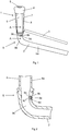
- Fig. 1 shows one teat cup 1 of a milking cluster.
- a complete milking cluster comprises usually two or four such teat cups 1.
- a short milk tube 2 is connected to the teat cup 1.
- the short milk tube is adapted to transport milk from the teat cup 1 to a not shown claw of the milking cluster.
- a pulse tube 3 is connected to the teat cup 1.
- the pulse tube 3 is adapted to transfer a pulsating pressure to the teat cup 1.
- the teat cup 1 comprises a mouthpiece 4 having an opening 5 to an inner space for receiving a teat of an animal during a milking process.
- the inner space of the teat cup 1 is defined by an inner surface of a flexible liner 6.
- the inner spaces of the liner 6 and an inner surface of short milk tube 2 form a milk passage for conducting milk from a teat of an animal to the claw during a milking process.
- the teat cup 1 comprises a rigid shell 7 enclosing the liner 6 in a manner such a pulsation chamber 8 is formed between the flexible liner 6 and the rigid shell 7.
- the short milk tube 2 and the liner 6 are here parts of a tubular element 9 formed in one-piece. In this case, the one-piece tubular element 9 also comprises the mouthpiece 4 of the teat cup 1.
- a substantially constant vacuum is applied to the milk passage of the tubular element 9.
- a pulsating vacuum is transferred to the pulsation chamber 8 of the teat cup 1 by means of the pulse tube 3.
- the liner 6 expands. The expanding motion of the liner 6 causes a pressure drop in the inner space of the liner 6. If at the same time an abundant flow of milk is present in the milk passage, there is a risk that the milk in the passage will be sucked backwards to the teat. In order to eliminate this risk, the short milk tube 2 has been provided with an additional material portion 9b including a vent passage 9c.
- the vent passage 9c comprises a through hole dimensioned to allow supply of air from the surrounding to the inner space of the tubular element 9 in a desired quantity. Thereby, the decreasing pressure in the inner space of the liner 6 is prevented to drop to a level at which the milk risks to be sucked backwards in the milk passage.
- the additional material portion 9b has here a substantially rectangular shape but of course it can have an arbitrary shape.
- the main part of the one-piece tubular element 9 constitutes of a first material portion 9a.
- the material in the first material portion 9a could be any suitable material normally used for short milk tubes and liners, for instance, a rubber material, a PVC material, a TPE material or a silicone material.
- the additional material portion 9b is made of another material than the material in the first material portion 9a.
- the additional material portion 9b can be made of a plastic material having stiffer properties than the material in the first material portion 9a. However, it is not excluded to use the same kind of material in the additional material portion 9b as in the first material portion 9a.
- the tubular element 9 in Fig. 1 has a curved portion 9e.
- Fig. 2 shows a cross section view of the curved portion 9e of the tubular element 9 in Fig. 1 . It is here visible that the first material portion 9a and the additional material portion 9b are fixedly connected to each other in a contact area 9d such that the material portions 9a, b form an integrated unit. Preferably, the first material portion 9a and the additional material portion 9b are moulded together in the contact area 9d.
- the tubular element 9 has an outer surface adapted to be in contact with a surrounding.
- the outer surface of the tubular element 9, which is adapted to be in contact with a surrounding is formed by an outer surface of the first material portion and an outer surface of the additional material portion.
- the outer surfaces 9a 1 , 9b 1 are arranged in relation to each other such that they form a smooth transition between each other at an outer part 9d 1 of the contact area. With such an even outer surface, the risk that dirt and bacteria are caught on the outer surface in the vicinity of the vent passage 9c is relatively small.
- the inner space of the tubular element is defined by an inner surface 9a 2 of the first material portion and an inner surface 9b 2 of the additional material portion 9b.
- the inner surfaces 9a 2 , 9b 2 are arranged in relation to each other such that they form a smooth transition between each other at an inner part 9d 2 of the contact area. Consequently, the tubular element 9 has an even inner surface also in this area of the milk passage. Thus, the risk is minimal that milk residues are collected on the inner surface of the tubular element 9 in the vicinity of the vent passage 9c.
- the tubular element 9 In a working position, the tubular element 9 is oriented such that the milk passage has a larger vertical inclination upstream the curved section 9e than downstream the curved section 9e with respect to the intended flow direction of the milk in the passage.
- the liner 6 forms mainly the vertical part of the milk passage upstream the curved portion 9e.
- the short milk tube 2 forms a relatively small part of the vertical part of the milk passage, the curved section 9e and a nearly horizontal part of the milk passage downstream the curved section 9e.
- the additional material portion 9b is, in Fig. 2 , positioned such that the vent passage 9c is located immediately upstream the curved section 9e with respect to the intended flow direction of the milk in the tubular element 9.
- the vent passage 9c secures the supply of air to the inner space of the liner 6 during the expansion of the liner 6.
- the existence of the vent passage 9c eliminates the risk of a backflow of milk in the milk passage.
- the vent passage 9c is here arranged above a radial inner part of the curved section 9e. In this position, the vent passage 9c is relatively protected from dirt and particles, which can whirl up from a floor of a milking stall.
- the vent passage 9c has a conical shape.
- the conical vent passage 9c has an inner opening 9c 2 to the inner space and an outer opening 9c 1 to the surrounding.
- the inner opening 9c 2 has a larger cross section area than the outer opening 9c 1 .
- vent passage 9c makes that milk in the milk passage, which has penetrated into the vent passage 9c, quickly flows back to the milk passage due to the conical surface of the vent passage 9c and the airflow. Furthermore, only particles having a smaller size than the inlet opening 9c 1 can penetrate into the vent passage 9c. Since the vent passage 9c has a conical shape, it expands in the flow direction of the air. Consequently, there is no risk that the particles block the vent passage 9c.
- Fig 3 shows an alternative positioning of the material portion 9b.
- the vent passage 9c is located in the curved section 9e.
- the vent passage 9c is arranged in a radial inner part of the curved section 9e. Due to the gravity, the main part of the milk flows in a radial outer part of the curved section 9e. Therefore, the milk in the passage rarely comes in contact with the vent passage 9c. Furthermore, the partially downwardly directed opening 9c 2 prevents milk from penetrating into the vent passage 9c.
- the milk passage of the curved section 9e has here been provided with a larger cross section area than adjacent sections of the milk passage. Thereby, the flow resistance in the curved section 9e is reduced which facilitates the milk flow through the tubular element 9. Furthermore, the risk that milk fills up the whole cross section area in the curved section 9c is reduced.
- the one-piece tubular element 9 is manufactured by means of a co-moulding process. It is easy to manufacture a tubular element 9 by two integrated material portions of different materials by such a moulding process.
- the additional material portion 9b is manufactured of a relatively stiff plastic material. Thereby, the vent passage 9c maintains its shape even if the tubular element 9 will be elastically deformed.
- the first material portion 9a can, for example, be manufactured of a silicon material.
- a co-moulding process is performed by means of a mould form defining the surfaces of the tubular element 9. Initially, the material of the additional material portion is injected into the mould form such that the additional material portion with the vent passage 9c is formed.
- the material of the first material portion 9a is injected into the mould form and on the initially formed additional material portion 9b.
- the first material portion 9a is here moulded together with the additional material portion 9b in the contact area 9d.
- the final moulded tubular element 9 constitutes a one-piece element.
- the material of the additional material portion 9b is injected into a first mould form such that the additional material portion 9b with the vent passage 9c is manufactured.
- the manufactured additional portion 9b is placed in a second mould form and the material of the first material portion 9a is injected into the second mould form and on the initially manufactured additional material portion 9b such that the material portions 9a, b are moulded together in the contact area 9d.
- the material of the first material portion 9a is injected into a mould form such that the first material portion 9a is manufactured. Thereafter, the material of the additional material portion 9b is injected into the mould form and on the initially manufactured first material portion 9a such that the material portions 9a, b are moulded together in the contact area 9d.
- the tubular element does not need to include a short milk tube and a liner.
- the tubular element can only include a short milk tube or a milk tube of an arbitrary kind.
- the tubular element does not need to have a curved section.
- the tubular element can be straight.
- the tubular element can have a cross section area of an arbitrary shape.
Landscapes
- Life Sciences & Earth Sciences (AREA)
- Animal Husbandry (AREA)
- Environmental Sciences (AREA)
- Dairy Products (AREA)
- External Artificial Organs (AREA)
- Medical Preparation Storing Or Oral Administration Devices (AREA)
Claims (13)
- Röhrenförmiges Element mit einem inneren Raum, der einen Durchgang zum Leiten von Milch ausbildet, wobei das röhrenförmige Element (9) einen ersten Materialabschnitt (9a), der den Hauptteil des röhrenförmigen Elements (9) bildet, und einen zusätzlichen Materialabschnitt (9b) umfasst, der einen Lüftungsdurchgang (9c) beinhaltet, der angepasst ist, um Luft in den inneren Raum des röhrenförmigen Elements (9) zuzuführen, und wobei der erste Materialabschnitt (9a) und der zusätzliche Materialabschnitt (9b) in Berührung miteinander in einem Berührungsbereich (9d) angeordnet sind, wobei der erste Materialabschnitt (9a) und der zusätzliche Materialabschnitt (9b) aus unterschiedlichen Materialien gefertigt sind und dass der erste Materialabschnitt (9a) und der zusätzliche Materialabschnitt (9b) in dem Berührungsbereich (9d) fest miteinander verbunden sind, sodass die Materialabschnitte (9a, b) eine integrierte Einheit ausbilden, dadurch gekennzeichnet, dass der erste Materialabschnitt (9a) und der zusätzliche Materialabschnitt (9b) in dem Berührungsbereich zusammen geformt sind.
- Röhrenförmiges Element nach Anspruch 1, dadurch gekennzeichnet, dass eine äußere Oberfläche des röhrenförmigen Elements (9), die angepasst ist, mit einer Umgebung in Berührung zu sein, durch eine äußere Oberfläche (9a1) des ersten Materialabschnittes und einer äußeren Oberfläche (9b1) des zusätzlichen Materialabschnittes ausgebildet ist, wobei die äußeren Oberflächen (9a1, 9b1) derart in Beziehung zueinander angeordnet sind, dass sie einen glatten Übergang an einem äußeren Teil (9d1) des Berührungsbereiches zwischen sich ausbilden.
- Röhrenförmiges Element nach einem der vorhergehenden Ansprüche, dadurch gekennzeichnet, dass der innere Raum des röhrenförmigen Elementes durch eine innere Oberfläche (9a2) des ersten Materialabschnittes und eine innere Oberfläche (9b2) des zusätzlichen Materialabschnittes (9b) definiert ist, wobei die inneren Oberflächen (9a2, 9b2) derart in Beziehung zueinander angeordnet sind, dass sie einen glatten Übergang an einem inneren Teil (9d2) des Berührungsbereiches zwischen sich ausbilden.
- Röhrenförmiges Element nach einem der vorhergehenden Ansprüche, dadurch gekennzeichnet, dass das röhrenförmige Element (9) wenigstens ein gekrümmtes Stück (9e) aufweist und dass der Lüftungsdurchgang (9c) stromaufwärts oder in dem gekrümmten Stück (9e) des röhrenförmigen Elementes bezüglich der vorgesehen Fließrichtung der Milch durch das röhrenförmige Element (9) gelegen ist.
- Röhrenförmiges Element nach Anspruch 4, dadurch gekennzeichnet, dass das röhrenförmige Element (9) angepasst ist, um in einer Arbeitsposition gelagert zu werden, in der der Milchdurchgang eine größere senkrechte Neigung stromaufwärts des gekrümmten Stücks (9e) als stromabwärts des gekrümmten Stücks bezüglich der vorgesehenen Fließrichtung der Milch durch das röhrenförmige Element (9) aufweist.
- Röhrenförmiges Element nach einem der Ansprüche 4 oder 5, dadurch gekennzeichnet, dass der zusätzliche Materialabschnitt (9b) derart positioniert ist, dass der Lüftungsdurchgang (9c) stromaufwärts, in oder stromabwärts eines radialen inneren Abschnitts des gekrümmten Stücks (9e) gelegen ist.
- Röhrenförmiges Element nach einem der vorhergehenden Ansprüche, dadurch gekennzeichnet, dass der Lüftungsdurchgang (9c) eine konische Form aufweist.
- Röhrenförmiges Element nach Anspruch 7, dadurch gekennzeichnet, dass der konische Lüftungsdurchlass (9c) eine innere Öffnung (9c2) zu dem inneren Raum des röhrenförmigen Elements (9) und eine äußere Öffnung (9c1) zu einer Umgebung aufweist, wobei die innere Öffnung (9c2) einen größeren Querschnittsbereich als die äußere Öffnung (9c1) aufweist.
- Röhrenförmiges Element nach einem der vorhergehenden Ansprüche, dadurch gekennzeichnet, dass das röhrenförmige Element (9) einen kurzen Milchschlauch (2) beinhaltet, der in einem Cluster zum Leiten von Milch aus einem Zitzenbecher (1) verwendet wird.
- Verfahren zum Herstellen eines röhrenförmigen Elements mit einem inneren Raum, der einen Durchgang zum Leiten von Milch ausbildet, wobei das Verfahren die folgenden Schritte umfasst: Herstellen des röhrenförmigen Elements (9) eines ersten Materialabschnittes (9a), der den Hauptteil des röhrenförmigen Elements (9) bildet, und eines zusätzlichen Materialabschnitts (9b) umfasst, der einen Lüftungsdurchgang (9c) beinhaltet, der angepasst ist, um Luft in den inneren Raum des röhrenförmigen Elements (9) zuzuführen, und Anordnen des ersten Materialabschnitts (9a) und des zusätzlichen Materialabschnitts (9b) derart, dass sie in einem Berührungsbereich (9d) in Berührung miteinander sind und sie in dem Berührungsbereich (9d) derart fest miteinander verbunden sind, dass die Materialabschnitte (9a, b) eine integrierte Einheit ausbilden, wobei der erste Materialabschnitt (9a) und der zusätzliche Materialabschnitt (9b) aus unterschiedlichen Materialien gefertigt sind, gekennzeichnet durch den Schritt des Verbindens des ersten Materialabschnitts (9a) und des zusätzlichen Materialabschnitts (9b) durch einen Formvorgang.
- Verfahren nach Anspruch 10, gekennzeichnet durch die Schritte des Einspritzens des Materials des zusätzlichen Materialabschnitts (9b) in eine Gussform derart, dass der zusätzliche Materialabschnitt (9b) mit dem Lüftungsdurchgang (9c) hergestellt wird, und Einspritzen des Materials des ersten Materialabschnitts (9a) in die Gussform und auf den anfänglich hergestellten zusätzlichen Materialabschnitt (9b) derart, dass die Materialabschnitte (9a, b) in dem Berührungsbereich (9d) zusammen geformt werden.
- Verfahren nach Anspruch 10, gekennzeichnet durch die Schritte des Einspritzens des Materials des zusätzlichen Materialabschnitts (9b) in eine erste Gussform derart, dass der zusätzliche Materialabschnitt (9b) mit dem Lüftungsdurchgang (9c) hergestellt wird, Platzieren des geformten zusätzlichen Abschnitts (9b) in eine zweite Gussform und Einspritzen des Materials des ersten Materialabschnitts (9a) in die zweite Gussform und auf den anfänglich hergestellten zusätzlichen Materialabschnitt (9b) derart, dass die Materialabschnitte (9a, b) in dem Berührungsbereich (9d) zusammen geformt werden.
- Verfahren nach Anspruch 10, gekennzeichnet durch die Schritte des Einspritzens des Materials des ersten Materialabschnitts (9a) in eine Gussform derart, dass der erste Materialabschnitt (9a) hergestellt wird, und des Einspritzens des Materials des zusätzlichen Materialabschnitts (9b) in die Gussform und auf den anfänglich hergestellten ersten Materialabschnitt (9a) derart, dass die Materialabschnitte (9a, b) in dem Berührungsbereich (9d) zusammen geformt werden.
Applications Claiming Priority (2)
| Application Number | Priority Date | Filing Date | Title |
|---|---|---|---|
| SE0702249 | 2007-10-08 | ||
| PCT/SE2008/051137 WO2009048417A1 (en) | 2007-10-08 | 2008-10-07 | A tubular element and a method for manufacturing thereof |
Publications (3)
| Publication Number | Publication Date |
|---|---|
| EP2197265A1 EP2197265A1 (de) | 2010-06-23 |
| EP2197265A4 EP2197265A4 (de) | 2017-07-26 |
| EP2197265B1 true EP2197265B1 (de) | 2019-05-15 |
Family
ID=40549411
Family Applications (1)
| Application Number | Title | Priority Date | Filing Date |
|---|---|---|---|
| EP08837086.1A Not-in-force EP2197265B1 (de) | 2007-10-08 | 2008-10-07 | Rohrförmiges element und verfahren zu seiner herstellung |
Country Status (8)
| Country | Link |
|---|---|
| US (1) | US8176872B2 (de) |
| EP (1) | EP2197265B1 (de) |
| CN (1) | CN101820744B (de) |
| AU (1) | AU2008311403A1 (de) |
| BR (1) | BRPI0818347A2 (de) |
| CA (1) | CA2702065A1 (de) |
| NZ (1) | NZ584583A (de) |
| WO (1) | WO2009048417A1 (de) |
Families Citing this family (10)
| Publication number | Priority date | Publication date | Assignee | Title |
|---|---|---|---|---|
| DE102007014535B4 (de) * | 2006-09-13 | 2010-12-09 | Gea Westfaliasurge Gmbh | Zitzengummi sowie Melkbecher mit einer Belüftungsdüse |
| US8056505B2 (en) * | 2009-12-08 | 2011-11-15 | Lauren Agrisystems, Ltd. | Vent for milking liner |
| US9357749B2 (en) | 2010-01-29 | 2016-06-07 | Gea Houle Inc. | Rotary milking station, kit for assembling the same, and methods of assembling and operating associated thereto |
| DE102013114987A1 (de) * | 2013-10-18 | 2015-04-23 | Happel WDA Besitz GbR (vertretungsberechtigter Gesellschafter: Werner Happel, 87654 Friesenried) | Zitzengummi und Düse |
| US10785952B2 (en) | 2014-11-07 | 2020-09-29 | Gea Farm Technologies, Inc. | Short milk tube with protective vent for a dairy animal milker unit |
| WO2016099384A1 (en) | 2014-12-19 | 2016-06-23 | Delaval Holding Ab | A teatcup |
| EP3285567A4 (de) * | 2015-04-22 | 2019-01-09 | Milkomax, Solutions Laitières Inc. | Verbesserung für melkbecher, melkstand und melkvorgänge |
| ITUB20159500A1 (it) * | 2015-12-22 | 2017-06-22 | Interpuls Spa | Guaina ventilata per impianti di mungitura |
| USD830649S1 (en) | 2016-01-28 | 2018-10-09 | Gea Farm Technologies, Inc. | Vent protecting stiffener for a dairy animal milker unit tube |
| US12178185B2 (en) * | 2022-01-14 | 2024-12-31 | Gea Farm Technologies, Inc. | Short milk tube vent plug for a dairy animal milker unit |
Family Cites Families (13)
| Publication number | Priority date | Publication date | Assignee | Title |
|---|---|---|---|---|
| GB644168A (en) | 1948-03-17 | 1950-10-04 | Harold Walter Burry | Improvements in teat cups for milking machines |
| US3476085A (en) * | 1967-12-27 | 1969-11-04 | Daniel O Noorlander | Air-vent for milking inflation |
| US3611993A (en) | 1969-11-10 | 1971-10-12 | Laval Separator Co De | Valving arrangement for operating teat cup liners |
| US3659558A (en) | 1970-03-23 | 1972-05-02 | Daniel O Noorlander | Teat cup inflation |
| US3967587A (en) | 1972-12-13 | 1976-07-06 | Noorlander Daniel O | Teat cup inflation |
| US4604969A (en) | 1985-06-17 | 1986-08-12 | Larson Leigh R | Milking inflation including air vent |
| NL1004921C2 (nl) | 1996-12-31 | 1998-07-01 | Prolion Bv | Inrichting en werkwijze voor het melken van dieren. |
| US6439157B1 (en) * | 1997-05-12 | 2002-08-27 | Delaval Holding Ab | Device arranged to permit an air flow from an environment to an inner space |
| US6055931A (en) | 1998-10-13 | 2000-05-02 | Dec International, Inc. | Clog resistant air vent plug for teatcup liner |
| SE515400C2 (sv) * | 1999-11-09 | 2001-07-30 | Delaval Holding Ab | Metod och anordning för att ställa in böjningsvinkel för en mjölkslang relativt en spenkopp |
| SE527446C2 (sv) * | 2004-06-10 | 2006-03-07 | Delaval Holding Ab | Mjölkningsanordningar |
| US7293527B2 (en) * | 2004-06-29 | 2007-11-13 | Lauren Agrisystems, Ltd. | Vent plug for milking liner |
| CA2570327C (en) * | 2004-06-29 | 2013-11-26 | Lauren Agrisystems, Ltd. | Milking liner |
-
2008
- 2008-10-07 BR BRPI0818347-3A patent/BRPI0818347A2/pt not_active IP Right Cessation
- 2008-10-07 NZ NZ584583A patent/NZ584583A/xx not_active IP Right Cessation
- 2008-10-07 CN CN2008801108355A patent/CN101820744B/zh not_active Expired - Fee Related
- 2008-10-07 WO PCT/SE2008/051137 patent/WO2009048417A1/en not_active Ceased
- 2008-10-07 US US12/681,938 patent/US8176872B2/en not_active Expired - Fee Related
- 2008-10-07 AU AU2008311403A patent/AU2008311403A1/en not_active Abandoned
- 2008-10-07 CA CA2702065A patent/CA2702065A1/en not_active Abandoned
- 2008-10-07 EP EP08837086.1A patent/EP2197265B1/de not_active Not-in-force
Non-Patent Citations (1)
| Title |
|---|
| None * |
Also Published As
| Publication number | Publication date |
|---|---|
| WO2009048417A1 (en) | 2009-04-16 |
| NZ584583A (en) | 2012-10-26 |
| EP2197265A1 (de) | 2010-06-23 |
| CN101820744B (zh) | 2013-02-13 |
| US8176872B2 (en) | 2012-05-15 |
| CA2702065A1 (en) | 2009-04-16 |
| AU2008311403A1 (en) | 2009-04-16 |
| BRPI0818347A2 (pt) | 2014-09-23 |
| EP2197265A4 (de) | 2017-07-26 |
| US20100275850A1 (en) | 2010-11-04 |
| CN101820744A (zh) | 2010-09-01 |
Similar Documents
| Publication | Publication Date | Title |
|---|---|---|
| US8176872B2 (en) | Tubular element and a method for manufacturing thereof | |
| CN102655738B (zh) | 接口件通气的挤奶杯内套 | |
| EP2192831B1 (de) | Zitzenbecherauskleidung | |
| US6055931A (en) | Clog resistant air vent plug for teatcup liner | |
| JP2006505353A (ja) | 人工乳首 | |
| JP4048485B2 (ja) | ティートカップライナのグループと、該グループの製造方法 | |
| CN106998667B (zh) | 用于奶畜挤奶器单元的带保护通气孔的短奶管 | |
| KR20080038132A (ko) | 보강된 인공 젖꼭지 | |
| US12178185B2 (en) | Short milk tube vent plug for a dairy animal milker unit | |
| US20150090183A1 (en) | Anti-twist Liner and Shell for a Dairy Animal Teat Cup Assembly | |
| US10070618B2 (en) | Milk conduit, a milk conduit device, a milk-receiving member and a milking member | |
| US6742475B1 (en) | Variable shut off teat cup liner | |
| JP2001526057A (ja) | 外部環境から内部空間への空気流入を可能にするように配置された装置 | |
| EP1608217B1 (de) | Melkbechersatz und melkglied | |
| CN114745947B (zh) | 挤奶杯 | |
| US8505485B2 (en) | Teat rubber with shock-absorbing properties | |
| WO2020059692A1 (ja) | 搾乳装置 | |
| WO1999034664A1 (en) | A teatcup liner device | |
| CN110536601A (zh) | 落管和设置有这种落管的旋转厅室喂食设备 | |
| RU64015U1 (ru) | Сосковая резина доильного аппарата |
Legal Events
| Date | Code | Title | Description |
|---|---|---|---|
| PUAI | Public reference made under article 153(3) epc to a published international application that has entered the european phase |
Free format text: ORIGINAL CODE: 0009012 |
|
| 17P | Request for examination filed |
Effective date: 20100409 |
|
| AK | Designated contracting states |
Kind code of ref document: A1 Designated state(s): AT BE BG CH CY CZ DE DK EE ES FI FR GB GR HR HU IE IS IT LI LT LU LV MC MT NL NO PL PT RO SE SI SK TR |
|
| AX | Request for extension of the european patent |
Extension state: AL BA MK RS |
|
| RIN1 | Information on inventor provided before grant (corrected) |
Inventor name: CRESPO, ERIC |
|
| DAX | Request for extension of the european patent (deleted) | ||
| RA4 | Supplementary search report drawn up and despatched (corrected) |
Effective date: 20170628 |
|
| RIC1 | Information provided on ipc code assigned before grant |
Ipc: A01J 5/08 20060101ALI20170622BHEP Ipc: A01J 5/04 20060101AFI20170622BHEP |
|
| REG | Reference to a national code |
Ref country code: DE Ref legal event code: R079 Ref document number: 602008060114 Country of ref document: DE Free format text: PREVIOUS MAIN CLASS: A01J0007000000 Ipc: A01J0005040000 |
|
| RIC1 | Information provided on ipc code assigned before grant |
Ipc: A01J 5/04 20060101AFI20181128BHEP Ipc: A01J 5/08 20060101ALI20181128BHEP |
|
| GRAP | Despatch of communication of intention to grant a patent |
Free format text: ORIGINAL CODE: EPIDOSNIGR1 |
|
| STAA | Information on the status of an ep patent application or granted ep patent |
Free format text: STATUS: GRANT OF PATENT IS INTENDED |
|
| INTG | Intention to grant announced |
Effective date: 20190115 |
|
| GRAS | Grant fee paid |
Free format text: ORIGINAL CODE: EPIDOSNIGR3 |
|
| GRAA | (expected) grant |
Free format text: ORIGINAL CODE: 0009210 |
|
| STAA | Information on the status of an ep patent application or granted ep patent |
Free format text: STATUS: THE PATENT HAS BEEN GRANTED |
|
| AK | Designated contracting states |
Kind code of ref document: B1 Designated state(s): AT BE BG CH CY CZ DE DK EE ES FI FR GB GR HR HU IE IS IT LI LT LU LV MC MT NL NO PL PT RO SE SI SK TR |
|
| REG | Reference to a national code |
Ref country code: CH Ref legal event code: EP Ref country code: GB Ref legal event code: FG4D |
|
| REG | Reference to a national code |
Ref country code: DE Ref legal event code: R096 Ref document number: 602008060114 Country of ref document: DE |
|
| REG | Reference to a national code |
Ref country code: IE Ref legal event code: FG4D |
|
| REG | Reference to a national code |
Ref country code: NL Ref legal event code: MP Effective date: 20190515 |
|
| REG | Reference to a national code |
Ref country code: LT Ref legal event code: MG4D |
|
| PG25 | Lapsed in a contracting state [announced via postgrant information from national office to epo] |
Ref country code: LT Free format text: LAPSE BECAUSE OF FAILURE TO SUBMIT A TRANSLATION OF THE DESCRIPTION OR TO PAY THE FEE WITHIN THE PRESCRIBED TIME-LIMIT Effective date: 20190515 Ref country code: HR Free format text: LAPSE BECAUSE OF FAILURE TO SUBMIT A TRANSLATION OF THE DESCRIPTION OR TO PAY THE FEE WITHIN THE PRESCRIBED TIME-LIMIT Effective date: 20190515 Ref country code: NO Free format text: LAPSE BECAUSE OF FAILURE TO SUBMIT A TRANSLATION OF THE DESCRIPTION OR TO PAY THE FEE WITHIN THE PRESCRIBED TIME-LIMIT Effective date: 20190815 Ref country code: PT Free format text: LAPSE BECAUSE OF FAILURE TO SUBMIT A TRANSLATION OF THE DESCRIPTION OR TO PAY THE FEE WITHIN THE PRESCRIBED TIME-LIMIT Effective date: 20190915 Ref country code: SE Free format text: LAPSE BECAUSE OF FAILURE TO SUBMIT A TRANSLATION OF THE DESCRIPTION OR TO PAY THE FEE WITHIN THE PRESCRIBED TIME-LIMIT Effective date: 20190515 Ref country code: FI Free format text: LAPSE BECAUSE OF FAILURE TO SUBMIT A TRANSLATION OF THE DESCRIPTION OR TO PAY THE FEE WITHIN THE PRESCRIBED TIME-LIMIT Effective date: 20190515 Ref country code: NL Free format text: LAPSE BECAUSE OF FAILURE TO SUBMIT A TRANSLATION OF THE DESCRIPTION OR TO PAY THE FEE WITHIN THE PRESCRIBED TIME-LIMIT Effective date: 20190515 Ref country code: ES Free format text: LAPSE BECAUSE OF FAILURE TO SUBMIT A TRANSLATION OF THE DESCRIPTION OR TO PAY THE FEE WITHIN THE PRESCRIBED TIME-LIMIT Effective date: 20190515 |
|
| PG25 | Lapsed in a contracting state [announced via postgrant information from national office to epo] |
Ref country code: BG Free format text: LAPSE BECAUSE OF FAILURE TO SUBMIT A TRANSLATION OF THE DESCRIPTION OR TO PAY THE FEE WITHIN THE PRESCRIBED TIME-LIMIT Effective date: 20190815 Ref country code: LV Free format text: LAPSE BECAUSE OF FAILURE TO SUBMIT A TRANSLATION OF THE DESCRIPTION OR TO PAY THE FEE WITHIN THE PRESCRIBED TIME-LIMIT Effective date: 20190515 Ref country code: GR Free format text: LAPSE BECAUSE OF FAILURE TO SUBMIT A TRANSLATION OF THE DESCRIPTION OR TO PAY THE FEE WITHIN THE PRESCRIBED TIME-LIMIT Effective date: 20190816 |
|
| REG | Reference to a national code |
Ref country code: AT Ref legal event code: MK05 Ref document number: 1132315 Country of ref document: AT Kind code of ref document: T Effective date: 20190515 |
|
| PG25 | Lapsed in a contracting state [announced via postgrant information from national office to epo] |
Ref country code: RO Free format text: LAPSE BECAUSE OF FAILURE TO SUBMIT A TRANSLATION OF THE DESCRIPTION OR TO PAY THE FEE WITHIN THE PRESCRIBED TIME-LIMIT Effective date: 20190515 Ref country code: AT Free format text: LAPSE BECAUSE OF FAILURE TO SUBMIT A TRANSLATION OF THE DESCRIPTION OR TO PAY THE FEE WITHIN THE PRESCRIBED TIME-LIMIT Effective date: 20190515 Ref country code: DK Free format text: LAPSE BECAUSE OF FAILURE TO SUBMIT A TRANSLATION OF THE DESCRIPTION OR TO PAY THE FEE WITHIN THE PRESCRIBED TIME-LIMIT Effective date: 20190515 Ref country code: EE Free format text: LAPSE BECAUSE OF FAILURE TO SUBMIT A TRANSLATION OF THE DESCRIPTION OR TO PAY THE FEE WITHIN THE PRESCRIBED TIME-LIMIT Effective date: 20190515 Ref country code: CZ Free format text: LAPSE BECAUSE OF FAILURE TO SUBMIT A TRANSLATION OF THE DESCRIPTION OR TO PAY THE FEE WITHIN THE PRESCRIBED TIME-LIMIT Effective date: 20190515 Ref country code: SK Free format text: LAPSE BECAUSE OF FAILURE TO SUBMIT A TRANSLATION OF THE DESCRIPTION OR TO PAY THE FEE WITHIN THE PRESCRIBED TIME-LIMIT Effective date: 20190515 |
|
| REG | Reference to a national code |
Ref country code: DE Ref legal event code: R097 Ref document number: 602008060114 Country of ref document: DE |
|
| PG25 | Lapsed in a contracting state [announced via postgrant information from national office to epo] |
Ref country code: IT Free format text: LAPSE BECAUSE OF FAILURE TO SUBMIT A TRANSLATION OF THE DESCRIPTION OR TO PAY THE FEE WITHIN THE PRESCRIBED TIME-LIMIT Effective date: 20190515 |
|
| PLBE | No opposition filed within time limit |
Free format text: ORIGINAL CODE: 0009261 |
|
| STAA | Information on the status of an ep patent application or granted ep patent |
Free format text: STATUS: NO OPPOSITION FILED WITHIN TIME LIMIT |
|
| PG25 | Lapsed in a contracting state [announced via postgrant information from national office to epo] |
Ref country code: TR Free format text: LAPSE BECAUSE OF FAILURE TO SUBMIT A TRANSLATION OF THE DESCRIPTION OR TO PAY THE FEE WITHIN THE PRESCRIBED TIME-LIMIT Effective date: 20190515 |
|
| 26N | No opposition filed |
Effective date: 20200218 |
|
| PG25 | Lapsed in a contracting state [announced via postgrant information from national office to epo] |
Ref country code: PL Free format text: LAPSE BECAUSE OF FAILURE TO SUBMIT A TRANSLATION OF THE DESCRIPTION OR TO PAY THE FEE WITHIN THE PRESCRIBED TIME-LIMIT Effective date: 20190515 |
|
| REG | Reference to a national code |
Ref country code: DE Ref legal event code: R119 Ref document number: 602008060114 Country of ref document: DE |
|
| PG25 | Lapsed in a contracting state [announced via postgrant information from national office to epo] |
Ref country code: SI Free format text: LAPSE BECAUSE OF FAILURE TO SUBMIT A TRANSLATION OF THE DESCRIPTION OR TO PAY THE FEE WITHIN THE PRESCRIBED TIME-LIMIT Effective date: 20190515 Ref country code: MC Free format text: LAPSE BECAUSE OF FAILURE TO SUBMIT A TRANSLATION OF THE DESCRIPTION OR TO PAY THE FEE WITHIN THE PRESCRIBED TIME-LIMIT Effective date: 20190515 |
|
| REG | Reference to a national code |
Ref country code: CH Ref legal event code: PL |
|
| PG25 | Lapsed in a contracting state [announced via postgrant information from national office to epo] |
Ref country code: CH Free format text: LAPSE BECAUSE OF NON-PAYMENT OF DUE FEES Effective date: 20191031 Ref country code: LI Free format text: LAPSE BECAUSE OF NON-PAYMENT OF DUE FEES Effective date: 20191031 Ref country code: LU Free format text: LAPSE BECAUSE OF NON-PAYMENT OF DUE FEES Effective date: 20191007 Ref country code: DE Free format text: LAPSE BECAUSE OF NON-PAYMENT OF DUE FEES Effective date: 20200501 |
|
| REG | Reference to a national code |
Ref country code: BE Ref legal event code: MM Effective date: 20191031 |
|
| PG25 | Lapsed in a contracting state [announced via postgrant information from national office to epo] |
Ref country code: BE Free format text: LAPSE BECAUSE OF NON-PAYMENT OF DUE FEES Effective date: 20191031 |
|
| GBPC | Gb: european patent ceased through non-payment of renewal fee |
Effective date: 20191007 |
|
| PG25 | Lapsed in a contracting state [announced via postgrant information from national office to epo] |
Ref country code: FR Free format text: LAPSE BECAUSE OF NON-PAYMENT OF DUE FEES Effective date: 20191031 Ref country code: GB Free format text: LAPSE BECAUSE OF NON-PAYMENT OF DUE FEES Effective date: 20191007 Ref country code: IE Free format text: LAPSE BECAUSE OF NON-PAYMENT OF DUE FEES Effective date: 20191007 |
|
| PG25 | Lapsed in a contracting state [announced via postgrant information from national office to epo] |
Ref country code: CY Free format text: LAPSE BECAUSE OF FAILURE TO SUBMIT A TRANSLATION OF THE DESCRIPTION OR TO PAY THE FEE WITHIN THE PRESCRIBED TIME-LIMIT Effective date: 20190515 |
|
| PG25 | Lapsed in a contracting state [announced via postgrant information from national office to epo] |
Ref country code: IS Free format text: LAPSE BECAUSE OF FAILURE TO SUBMIT A TRANSLATION OF THE DESCRIPTION OR TO PAY THE FEE WITHIN THE PRESCRIBED TIME-LIMIT Effective date: 20190915 |
|
| PG25 | Lapsed in a contracting state [announced via postgrant information from national office to epo] |
Ref country code: HU Free format text: LAPSE BECAUSE OF FAILURE TO SUBMIT A TRANSLATION OF THE DESCRIPTION OR TO PAY THE FEE WITHIN THE PRESCRIBED TIME-LIMIT; INVALID AB INITIO Effective date: 20081007 Ref country code: MT Free format text: LAPSE BECAUSE OF FAILURE TO SUBMIT A TRANSLATION OF THE DESCRIPTION OR TO PAY THE FEE WITHIN THE PRESCRIBED TIME-LIMIT Effective date: 20190515 |