EP2197330B1 - Vorrichtung zur sammlung von schmutz in einer saugvorrichtung - Google Patents
Vorrichtung zur sammlung von schmutz in einer saugvorrichtung Download PDFInfo
- Publication number
- EP2197330B1 EP2197330B1 EP08787347.7A EP08787347A EP2197330B1 EP 2197330 B1 EP2197330 B1 EP 2197330B1 EP 08787347 A EP08787347 A EP 08787347A EP 2197330 B1 EP2197330 B1 EP 2197330B1
- Authority
- EP
- European Patent Office
- Prior art keywords
- container
- sack
- attachment
- lid
- hole
- Prior art date
- Legal status (The legal status is an assumption and is not a legal conclusion. Google has not performed a legal analysis and makes no representation as to the accuracy of the status listed.)
- Active
Links
- 239000000428 dust Substances 0.000 description 5
- 239000012535 impurity Substances 0.000 description 3
- 230000000694 effects Effects 0.000 description 2
- 230000005484 gravity Effects 0.000 description 2
- 239000000463 material Substances 0.000 description 2
- 238000007792 addition Methods 0.000 description 1
- 230000001419 dependent effect Effects 0.000 description 1
- 239000000284 extract Substances 0.000 description 1
- 230000004048 modification Effects 0.000 description 1
- 238000012986 modification Methods 0.000 description 1
- 239000007787 solid Substances 0.000 description 1
Images


Classifications
-
- A—HUMAN NECESSITIES
- A47—FURNITURE; DOMESTIC ARTICLES OR APPLIANCES; COFFEE MILLS; SPICE MILLS; SUCTION CLEANERS IN GENERAL
- A47L—DOMESTIC WASHING OR CLEANING; SUCTION CLEANERS IN GENERAL
- A47L9/00—Details or accessories of suction cleaners, e.g. mechanical means for controlling the suction or for effecting pulsating action; Storing devices specially adapted to suction cleaners or parts thereof; Carrying-vehicles specially adapted for suction cleaners
- A47L9/10—Filters; Dust separators; Dust removal; Automatic exchange of filters
- A47L9/14—Bags or the like; Rigid filtering receptacles; Attachment of, or closures for, bags or receptacles
- A47L9/1427—Means for mounting or attaching bags or filtering receptacles in suction cleaners; Adapters
- A47L9/1436—Connecting plates, e.g. collars, end closures
- A47L9/1445—Connecting plates, e.g. collars, end closures with closure means
- A47L9/1454—Self-sealing closures, e.g. valves
-
- A—HUMAN NECESSITIES
- A47—FURNITURE; DOMESTIC ARTICLES OR APPLIANCES; COFFEE MILLS; SPICE MILLS; SUCTION CLEANERS IN GENERAL
- A47L—DOMESTIC WASHING OR CLEANING; SUCTION CLEANERS IN GENERAL
- A47L9/00—Details or accessories of suction cleaners, e.g. mechanical means for controlling the suction or for effecting pulsating action; Storing devices specially adapted to suction cleaners or parts thereof; Carrying-vehicles specially adapted for suction cleaners
- A47L9/009—Carrying-vehicles; Arrangements of trollies or wheels; Means for avoiding mechanical obstacles
Definitions
- the present invention concerns a device for the collection of dirt in a suction apparatus, for example a vacuum cleaner, an electric brush or similar apparatuses.
- the device is used to close, automatically, the sack for collecting dirt sucked in when it has to be replaced.
- DE 3919256 discloses the features of the preamble of claim 1.
- a device for closing a sack for the collection of dirt, used in a suction apparatus, comprising a closing element mounted sliding inside a plate attached to the sack and provided with a hole to allow the dirty air sucked in by the apparatus to enter into the sack.
- the closing element is able to close the hole of said plate when the sack has to be removed, so that the dust contained inside it does not come out.
- Another disadvantage of the known device is that releasing the sack from the compartment of the suction apparatus in which it is normally located and attached, is also done manually. This entails inconvenient operations by the user to replace the sack, with the risk that dust and impurities can come out of the sack.
- Purpose of the present invention is to achieve a device for closing a sack for the collection of dirt, to be used in a suction apparatus, which allows the user of the apparatus not to come into contact with the dust and impurities in the sack, and also to replace the sack quickly and easily.
- the Applicant has devised, tested and embodied the present invention to overcome the shortcomings of the state of the art and to obtain these and other purposes and advantages.
- a device to close a sack for the collection of dirt used in a suction apparatus for example a vacuum cleaner, an electric brush or similar apparatuses, comprises a container able to contain the sack.
- the latter comprises a plate provided with a first hole able to allow the passage of the air sucked in by the apparatus inside the sack, and closing means mounted sliding on said plate, able to close said first hole.
- the container comprises drive means, able to be driven manually by the user, and to cooperate with the plate. Furthermore, the container comprises first attachment means, able to cooperate with said closing means.
- said drive means comprises a lid pivoted on a fixed part of the container.
- the lid advantageously comprises second attachment means, able to attach corresponding third attachment means, with which said plate is provided, to cooperate with the plate.
- said closing means comprises a shutter element, for example consisting of a sliding wall, provided with fourth attachment means, able to attach said first attachment means of the container.
- the shutter element is also provided with a second hole, of substantially the same size as the first hole and able to coincide with the latter, when the shutter element is in a determinate position inside said plate.
- the plate and the shutter element are attached to the corresponding attachment means and the shutter element is in said determinate position, in which the second hole and the first hole coincide, allowing the dirty air sucked in to flow inside the sack.
- the shutter element remains in any case attached to the first attachment means of the container, whereas the plate, attached to the second attachment means of the lid, is drawn by the latter upward together with the sack.
- the first hole of the plate is closed by the shutter element
- the plate and the shutter element are constrained by the corresponding attachment means.
- the sack falls automatically inside the container, ready to be collected by the user and thrown away, so that the replacement of the sack is quick and easy.
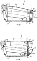
- a device 10 for closing a sack 11 for the collection of dirt is able to be used in a suction apparatus of a known type, not shown in the drawings.
- the device 10 comprises a container 12, made of plastic material, which is shaped so as to have a circular aperture 13 at one end. Below the circular aperture 13 and outside the container 12, a mobile pipe 14 is pivoted, able to be inserted inside the circular aperture 13. In the mobile pipe 14, furthermore, a sleeve is able to be inserted, of a known type and not shown in the drawings, to convey the dirty air, sucked in by the suction apparatus, inside the container 12, in particular inside the sack 11, as will be described in detail hereafter.
- the mobile pipe 14 also comprises at its upper part an attachment hole 15.
- the sack 11 is able to be disposed inside the container 12 and comprises, at one end, a rigid plate 16, also, for example, made of plastic material.
- the rigid plate 16 is substantially square in shape and is provided, in its upper part, with a first attachment element, or upper attachment 17.
- the rigid plate 16 is provided at the center with a first circular hole 18, with a diameter substantially equal to that of the circular aperture 13 and into which the mobile pipe 14 is able to be inserted, in order to guarantee the sack 11 a greater stability inside the container 12 and to prevent loss of efficiency of the suction apparatus.
- a closing wall 19, substantially rectangular in shape, is mounted sliding inside the rigid plate 16 so as to act as a shutter element 19.
- the closing wall 19 comprises at the lower part a second attachment element, or lower attachment 20, able to attach a corresponding attachment tooth 21 ( fig. 3 ) made inside the container 12 below the circular aperture 13.
- the lower attachment 20 is also able to prevent the closing wall 19 from coming out of the rigid plate 16.
- the closing wall 19 is also provided in its lower half with a second circular hole 23 with a diameter substantially equal to that of the first circular hole 18.
- the container 12 In proximity with said attachment tooth 21, the container 12 is also provided with a guide plate 22, substantially rectangular in shape, disposed transverse to the container 12 and solid with a lateral wall thereof, able to guide the lower attachment 20 in correspondence with the first attachment tooth 21, to make the attachment.
- a lid 24 is pivoted on a fixed part of the container 12, above and at the opposite end to that where there is the circular aperture 13.
- the lid 24 is provided, inside and at the opposite end to that where it is pivoted to the container 12, with an attachment element 25, provided with three teeth 26, 27, 28 disposed so as to form a substantially cross-shaped profile.
- the device 10 functions as follows.
- the container 12, containing the sack 11 is closed by the lid 24.
- the sack 11 is attached to the container 12 and to the lid 24 by means of the lower attachment 20 of the closing wall 19 and the upper attachment 17 of the rigid plate 16, attached respectively to the attachment tooth 21 and the first tooth 26 of the attachment element 25.
- the closing wall 19 is in a position such that its second circular hole 23 and the first circular hole 18 of the rigid plate 16 coincide.
- the user of the suction apparatus extracts the mobile pipe 14 from the sack 11 and from the container 12, making it rotate on the pins by means of which it is pivoted to the container 12 ( fig. 4 ). Subsequently, the latter is opened by lifting the lid 24 and making it rotate.
- the closing wall 19 remains attached by means of the lower attachment 20 to the attachment tooth 21, whereas the rigid plate 16, attached to the first tooth 26 of the attachment element 25 of the lid 24, is drawn by the latter upward, together with the sack 11. In this way, as a consequence of the sliding of the rigid plate 16 with respect to the closing wall 19, the first hole 18 of the rigid plate 16 is closed by that part of the closing wall 19 where there is not the second hole 23, in practice automatically closing the sack 11.
Landscapes
- Engineering & Computer Science (AREA)
- Mechanical Engineering (AREA)
- Nozzles For Electric Vacuum Cleaners (AREA)
- Closures For Containers (AREA)
- Filters For Electric Vacuum Cleaners (AREA)
- Apparatus Associated With Microorganisms And Enzymes (AREA)
- Dry Shavers And Clippers (AREA)
- External Artificial Organs (AREA)
Claims (4)
- Vorrichtung zum Sammeln von Schmutz, verwendet in einem Saugapparat, beinhaltend einen Behälter (12), der dazu ausgebildet ist, eine kreisförmige Öffnung (13) an einem Ende zu haben und der dazu eingerichtet ist, einen Sack (11) aufzunehmen, wobei der Sack (11) mit einer Platte (16) versehen ist, die ein erstes Loch (18) aufweist, das den Eingang der vom Apparat angesaugten Luft in das Innere des besagten Sacks (11) erlaubt, und eine Verschlusswand (19) die verschieblich an besagter Platte (16) angebracht ist und die in ihrer unteren Hälfte mit einem zweiten Loch (23) versehen ist, das während des Gebrauchs des Saugapparates mit dem ersten Loch (18) ausgerichtet, wobei die Größe des zweiten Lochs (23) mit der des ersten Lochs (18) im Wesentlichen gleich ist, wobei die Vorrichtung weiter einen Deckel (24) beinhaltet, der um einen festen Teil des Behälters (12) verschwenkbar ist, dadurch gekennzeichnet, dass in der geschlossenen Position des Deckels (24) am Behälter (12), die Platte (16) mittels eines ersten Befestigungselements oder oberen Elements (17), am Deckel (24) befestigt ist, wobei das obere Element (17) dazu eingerichtet ist einen ersten Zahn (26) eines Befestigungselement (25) festzulegen, das an dem Deckel (26) angeordnet ist und in Richtung zum Inneren des Behälters (12) ragt, und die Verschlusswand (19) am Behälter (12) mittels eines zweiten Befestigungselements oder unteren Elements (20) befestigt ist, das einen entsprechenden Befestigungszahn (21), der im Behälter (12) unterhalb der Kreisöffnung (13) angeordnet ist, festlegt wobei, in einer ersten Position des Deckels (24) in Bezug auf den besagten Behälter (12), die besagte Platte (16) in Bezug auf die Verschlusswand (19) angehoben ist, so dass die jeweiligen Löcher (18, 23) nichtfluchtend ausgerichtet sind, um den Sack (11) automatisch zu verschließen, wobei die Verschlusswand (19) über das untere Befestigungselements (20) am Befestigungszahn (21) befestigt bleibt, während die am ersten Zahn (26) befestigte steife Platte (16) durch den Deckel (24) zusammen mit dem Sack (11) aufwärts gezogen wird, und wobei in einer zweiten offenen Position des Deckels (24) in Bezug auf den Behälter (12), der einen größeren Winkel hat als in der ersten Position, automatisch sofort zu schließen angehoben und, wird die Verschlusswand (19) vom Behälter (12) freigegeben wird so dass der geschlossene Sack (11) in den Behälter (12) zu hinein fällt.
- Vorrichtung nach Anspruch 1, dadurch gekennzeichnet, dass sie auch ein Rohr (14) beinhaltet, das zu einem Ende des besagtem Behälters (12) geschwenkt wird und fähig ist, in besagtes erstes Loch (18) besagter Platte (16) eingefügt zu werden.
- Vorrichtung nach Anspruch 2, dadurch gekennzeichnet, dass das besagte Rohr (14) eine Aufnahmebohrung (15) beinhaltet, in die ein entsprechendes Befestigungsmittel (27) des besagten Deckels (24) eingeführt werden kann.
- Vorrichtung nach Anspruch 1, dadurch gekennzeichnet, dass der besagte Behälter (12) in sich ein Führungselement (22) beinhaltet, das eingerichtet ist die Verschlusswand (19) zu führen, um die zweiten Befestigungsmittel (20), mit den ersten Befestigungsmitteln (21) zusammenwirken zu lassen.
Applications Claiming Priority (2)
| Application Number | Priority Date | Filing Date | Title |
|---|---|---|---|
| ITUD20070148 ITUD20070148A1 (it) | 2007-08-28 | 2007-08-28 | Dispositivo per la raccolta dello sporco per un'apparecchiatura di aspirazione |
| PCT/EP2008/060898 WO2009027289A1 (en) | 2007-08-28 | 2008-08-20 | Device for the collection of dirt in a suction apparatus |
Publications (2)
| Publication Number | Publication Date |
|---|---|
| EP2197330A1 EP2197330A1 (de) | 2010-06-23 |
| EP2197330B1 true EP2197330B1 (de) | 2016-05-25 |
Family
ID=39885207
Family Applications (1)
| Application Number | Title | Priority Date | Filing Date |
|---|---|---|---|
| EP08787347.7A Active EP2197330B1 (de) | 2007-08-28 | 2008-08-20 | Vorrichtung zur sammlung von schmutz in einer saugvorrichtung |
Country Status (5)
| Country | Link |
|---|---|
| EP (1) | EP2197330B1 (de) |
| CN (1) | CN101795611B (de) |
| ES (1) | ES2587733T3 (de) |
| IT (1) | ITUD20070148A1 (de) |
| WO (1) | WO2009027289A1 (de) |
Families Citing this family (1)
| Publication number | Priority date | Publication date | Assignee | Title |
|---|---|---|---|---|
| WO2022245736A1 (en) * | 2021-05-17 | 2022-11-24 | Techtronic Cordless Gp | Vacuum cleaner and filter bag |
Family Cites Families (6)
| Publication number | Priority date | Publication date | Assignee | Title |
|---|---|---|---|---|
| GB623033A (en) * | 1945-09-22 | 1949-05-11 | Electrolux Corp | Improvements in or relating to vacuum cleaners |
| US2815090A (en) * | 1955-01-14 | 1957-12-03 | Hoover Co | Filter mounting means |
| DE3919256A1 (de) * | 1989-06-13 | 1990-12-20 | Miele & Cie | Staubfilterbeutel insbesondere fuer staubsauger |
| EP0409038B1 (de) * | 1989-07-21 | 1994-03-16 | Siemens Aktiengesellschaft | Staubsaugerfilterbeutel mit einer steifen Halteplatte |
| IT1285537B1 (it) * | 1996-10-22 | 1998-06-08 | Gisowatt Spa Ind Elettrodomest | Sacchetto raccogli-polvere per scope elettriche e simili a chiusura automatica |
| FR2870704B1 (fr) * | 2004-05-26 | 2006-07-07 | Seb Sa | Dispositif de recuperation des dechets dans un aspirateur |
-
2007
- 2007-08-28 IT ITUD20070148 patent/ITUD20070148A1/it unknown
-
2008
- 2008-08-20 CN CN200880105710.3A patent/CN101795611B/zh active Active
- 2008-08-20 EP EP08787347.7A patent/EP2197330B1/de active Active
- 2008-08-20 WO PCT/EP2008/060898 patent/WO2009027289A1/en not_active Ceased
- 2008-08-20 ES ES08787347.7T patent/ES2587733T3/es active Active
Also Published As
| Publication number | Publication date |
|---|---|
| CN101795611A (zh) | 2010-08-04 |
| WO2009027289A1 (en) | 2009-03-05 |
| CN101795611B (zh) | 2013-08-28 |
| ES2587733T3 (es) | 2016-10-26 |
| EP2197330A1 (de) | 2010-06-23 |
| ITUD20070148A1 (it) | 2009-02-28 |
Similar Documents
| Publication | Publication Date | Title |
|---|---|---|
| KR102124512B1 (ko) | 사이클론 집진장치 및 이를 갖는 진공 청소기 | |
| EP3964115A1 (de) | Vorrichtung zur staubabscheidung und reinigungsvorrichtungsanordnung damit | |
| JP6455736B2 (ja) | 手持ち真空掃除機 | |
| ES2919565T3 (es) | Estación base para una aspiradora | |
| KR20200062123A (ko) | 청소기 | |
| JP2022509096A (ja) | 取り外し可能な容器を有する真空掃除機 | |
| CN111432702A (zh) | 清洁器 | |
| EP2721985A2 (de) | Vorrichtung zum anschliessen eines staubsaugerbeutels | |
| TWI744595B (zh) | 清掃機 | |
| CN106998974A (zh) | 空气流式清洁设备 | |
| CN108135413A (zh) | 旋风灰尘收集器及具有其的真空吸尘器 | |
| CN208864225U (zh) | 吸水地刷及其清洗机 | |
| CN216221352U (zh) | 一种洗地机的防粘污水箱及其洗地机 | |
| EP2197330B1 (de) | Vorrichtung zur sammlung von schmutz in einer saugvorrichtung | |
| CN206213940U (zh) | 料理机 | |
| CN115697163A (zh) | 吸尘器 | |
| CN203861138U (zh) | 集尘装置以及设有该集尘装置的集尘系统 | |
| ITUD990115A1 (it) | Apparecchio di pulizia ad aspirazione | |
| EP2524641A2 (de) | Vorrichtung zum Sammeln von aufgesaugten Materialien zur Verwendung in Staubsaugergeräten | |
| LU503991B1 (de) | Sauggerät | |
| KR200488006Y1 (ko) | 청소기의 굵은 쓰레기 걸림 장치 | |
| CN205795471U (zh) | 一种榨汁机 | |
| JP2017060848A (ja) | 電気掃除機 | |
| CN210788443U (zh) | 一种自动铝壳收集装置 | |
| CN201791450U (zh) | 集尘机 |
Legal Events
| Date | Code | Title | Description |
|---|---|---|---|
| PUAI | Public reference made under article 153(3) epc to a published international application that has entered the european phase |
Free format text: ORIGINAL CODE: 0009012 |
|
| 17P | Request for examination filed |
Effective date: 20100318 |
|
| AK | Designated contracting states |
Kind code of ref document: A1 Designated state(s): AT BE BG CH CY CZ DE DK EE ES FI FR GB GR HR HU IE IS IT LI LT LU LV MC MT NL NO PL PT RO SE SI SK TR |
|
| AX | Request for extension of the european patent |
Extension state: AL BA MK RS |
|
| DAX | Request for extension of the european patent (deleted) | ||
| 17Q | First examination report despatched |
Effective date: 20111201 |
|
| REG | Reference to a national code |
Ref country code: DE Ref legal event code: R079 Ref document number: 602008044427 Country of ref document: DE Free format text: PREVIOUS MAIN CLASS: A47L0009140000 Ipc: A47L0009000000 |
|
| GRAP | Despatch of communication of intention to grant a patent |
Free format text: ORIGINAL CODE: EPIDOSNIGR1 |
|
| RIC1 | Information provided on ipc code assigned before grant |
Ipc: A47L 9/14 20060101ALI20151016BHEP Ipc: A47L 9/00 20060101AFI20151016BHEP |
|
| INTG | Intention to grant announced |
Effective date: 20151119 |
|
| GRAS | Grant fee paid |
Free format text: ORIGINAL CODE: EPIDOSNIGR3 |
|
| GRAA | (expected) grant |
Free format text: ORIGINAL CODE: 0009210 |
|
| RAP1 | Party data changed (applicant data changed or rights of an application transferred) |
Owner name: DE' LONGHI S.P.A |
|
| AK | Designated contracting states |
Kind code of ref document: B1 Designated state(s): AT BE BG CH CY CZ DE DK EE ES FI FR GB GR HR HU IE IS IT LI LT LU LV MC MT NL NO PL PT RO SE SI SK TR |
|
| REG | Reference to a national code |
Ref country code: GB Ref legal event code: FG4D |
|
| REG | Reference to a national code |
Ref country code: CH Ref legal event code: EP |
|
| REG | Reference to a national code |
Ref country code: IE Ref legal event code: FG4D Ref country code: AT Ref legal event code: REF Ref document number: 801525 Country of ref document: AT Kind code of ref document: T Effective date: 20160615 |
|
| REG | Reference to a national code |
Ref country code: DE Ref legal event code: R096 Ref document number: 602008044427 Country of ref document: DE |
|
| REG | Reference to a national code |
Ref country code: FR Ref legal event code: PLFP Year of fee payment: 9 |
|
| REG | Reference to a national code |
Ref country code: LT Ref legal event code: MG4D |
|
| REG | Reference to a national code |
Ref country code: NL Ref legal event code: MP Effective date: 20160525 |
|
| REG | Reference to a national code |
Ref country code: ES Ref legal event code: FG2A Ref document number: 2587733 Country of ref document: ES Kind code of ref document: T3 Effective date: 20161026 |
|
| PG25 | Lapsed in a contracting state [announced via postgrant information from national office to epo] |
Ref country code: FI Free format text: LAPSE BECAUSE OF FAILURE TO SUBMIT A TRANSLATION OF THE DESCRIPTION OR TO PAY THE FEE WITHIN THE PRESCRIBED TIME-LIMIT Effective date: 20160525 Ref country code: NO Free format text: LAPSE BECAUSE OF FAILURE TO SUBMIT A TRANSLATION OF THE DESCRIPTION OR TO PAY THE FEE WITHIN THE PRESCRIBED TIME-LIMIT Effective date: 20160825 Ref country code: NL Free format text: LAPSE BECAUSE OF FAILURE TO SUBMIT A TRANSLATION OF THE DESCRIPTION OR TO PAY THE FEE WITHIN THE PRESCRIBED TIME-LIMIT Effective date: 20160525 Ref country code: LT Free format text: LAPSE BECAUSE OF FAILURE TO SUBMIT A TRANSLATION OF THE DESCRIPTION OR TO PAY THE FEE WITHIN THE PRESCRIBED TIME-LIMIT Effective date: 20160525 |
|
| REG | Reference to a national code |
Ref country code: AT Ref legal event code: MK05 Ref document number: 801525 Country of ref document: AT Kind code of ref document: T Effective date: 20160525 |
|
| PG25 | Lapsed in a contracting state [announced via postgrant information from national office to epo] |
Ref country code: SE Free format text: LAPSE BECAUSE OF FAILURE TO SUBMIT A TRANSLATION OF THE DESCRIPTION OR TO PAY THE FEE WITHIN THE PRESCRIBED TIME-LIMIT Effective date: 20160525 Ref country code: HR Free format text: LAPSE BECAUSE OF FAILURE TO SUBMIT A TRANSLATION OF THE DESCRIPTION OR TO PAY THE FEE WITHIN THE PRESCRIBED TIME-LIMIT Effective date: 20160525 Ref country code: LV Free format text: LAPSE BECAUSE OF FAILURE TO SUBMIT A TRANSLATION OF THE DESCRIPTION OR TO PAY THE FEE WITHIN THE PRESCRIBED TIME-LIMIT Effective date: 20160525 Ref country code: PT Free format text: LAPSE BECAUSE OF FAILURE TO SUBMIT A TRANSLATION OF THE DESCRIPTION OR TO PAY THE FEE WITHIN THE PRESCRIBED TIME-LIMIT Effective date: 20160926 |
|
| PG25 | Lapsed in a contracting state [announced via postgrant information from national office to epo] |
Ref country code: BE Free format text: LAPSE BECAUSE OF NON-PAYMENT OF DUE FEES Effective date: 20160831 |
|
| PG25 | Lapsed in a contracting state [announced via postgrant information from national office to epo] |
Ref country code: SK Free format text: LAPSE BECAUSE OF FAILURE TO SUBMIT A TRANSLATION OF THE DESCRIPTION OR TO PAY THE FEE WITHIN THE PRESCRIBED TIME-LIMIT Effective date: 20160525 Ref country code: RO Free format text: LAPSE BECAUSE OF FAILURE TO SUBMIT A TRANSLATION OF THE DESCRIPTION OR TO PAY THE FEE WITHIN THE PRESCRIBED TIME-LIMIT Effective date: 20160525 Ref country code: CZ Free format text: LAPSE BECAUSE OF FAILURE TO SUBMIT A TRANSLATION OF THE DESCRIPTION OR TO PAY THE FEE WITHIN THE PRESCRIBED TIME-LIMIT Effective date: 20160525 Ref country code: EE Free format text: LAPSE BECAUSE OF FAILURE TO SUBMIT A TRANSLATION OF THE DESCRIPTION OR TO PAY THE FEE WITHIN THE PRESCRIBED TIME-LIMIT Effective date: 20160525 Ref country code: DK Free format text: LAPSE BECAUSE OF FAILURE TO SUBMIT A TRANSLATION OF THE DESCRIPTION OR TO PAY THE FEE WITHIN THE PRESCRIBED TIME-LIMIT Effective date: 20160525 |
|
| REG | Reference to a national code |
Ref country code: GR Ref legal event code: EP Ref document number: 20160402014 Country of ref document: GR Effective date: 20161118 |
|
| PG25 | Lapsed in a contracting state [announced via postgrant information from national office to epo] |
Ref country code: BE Free format text: LAPSE BECAUSE OF FAILURE TO SUBMIT A TRANSLATION OF THE DESCRIPTION OR TO PAY THE FEE WITHIN THE PRESCRIBED TIME-LIMIT Effective date: 20160525 Ref country code: AT Free format text: LAPSE BECAUSE OF FAILURE TO SUBMIT A TRANSLATION OF THE DESCRIPTION OR TO PAY THE FEE WITHIN THE PRESCRIBED TIME-LIMIT Effective date: 20160525 Ref country code: PL Free format text: LAPSE BECAUSE OF FAILURE TO SUBMIT A TRANSLATION OF THE DESCRIPTION OR TO PAY THE FEE WITHIN THE PRESCRIBED TIME-LIMIT Effective date: 20160525 |
|
| REG | Reference to a national code |
Ref country code: DE Ref legal event code: R097 Ref document number: 602008044427 Country of ref document: DE |
|
| PG25 | Lapsed in a contracting state [announced via postgrant information from national office to epo] |
Ref country code: MC Free format text: LAPSE BECAUSE OF FAILURE TO SUBMIT A TRANSLATION OF THE DESCRIPTION OR TO PAY THE FEE WITHIN THE PRESCRIBED TIME-LIMIT Effective date: 20160525 |
|
| PLBE | No opposition filed within time limit |
Free format text: ORIGINAL CODE: 0009261 |
|
| REG | Reference to a national code |
Ref country code: CH Ref legal event code: PL |
|
| STAA | Information on the status of an ep patent application or granted ep patent |
Free format text: STATUS: NO OPPOSITION FILED WITHIN TIME LIMIT |
|
| GBPC | Gb: european patent ceased through non-payment of renewal fee |
Effective date: 20160825 |
|
| PG25 | Lapsed in a contracting state [announced via postgrant information from national office to epo] |
Ref country code: LI Free format text: LAPSE BECAUSE OF NON-PAYMENT OF DUE FEES Effective date: 20160831 Ref country code: CH Free format text: LAPSE BECAUSE OF NON-PAYMENT OF DUE FEES Effective date: 20160831 |
|
| 26N | No opposition filed |
Effective date: 20170228 |
|
| PG25 | Lapsed in a contracting state [announced via postgrant information from national office to epo] |
Ref country code: SI Free format text: LAPSE BECAUSE OF FAILURE TO SUBMIT A TRANSLATION OF THE DESCRIPTION OR TO PAY THE FEE WITHIN THE PRESCRIBED TIME-LIMIT Effective date: 20160525 |
|
| REG | Reference to a national code |
Ref country code: IE Ref legal event code: MM4A |
|
| PG25 | Lapsed in a contracting state [announced via postgrant information from national office to epo] |
Ref country code: IE Free format text: LAPSE BECAUSE OF NON-PAYMENT OF DUE FEES Effective date: 20160820 Ref country code: GB Free format text: LAPSE BECAUSE OF NON-PAYMENT OF DUE FEES Effective date: 20160825 |
|
| REG | Reference to a national code |
Ref country code: FR Ref legal event code: PLFP Year of fee payment: 10 |
|
| PG25 | Lapsed in a contracting state [announced via postgrant information from national office to epo] |
Ref country code: LU Free format text: LAPSE BECAUSE OF NON-PAYMENT OF DUE FEES Effective date: 20160820 |
|
| PG25 | Lapsed in a contracting state [announced via postgrant information from national office to epo] |
Ref country code: CY Free format text: LAPSE BECAUSE OF FAILURE TO SUBMIT A TRANSLATION OF THE DESCRIPTION OR TO PAY THE FEE WITHIN THE PRESCRIBED TIME-LIMIT Effective date: 20160525 Ref country code: HU Free format text: LAPSE BECAUSE OF FAILURE TO SUBMIT A TRANSLATION OF THE DESCRIPTION OR TO PAY THE FEE WITHIN THE PRESCRIBED TIME-LIMIT; INVALID AB INITIO Effective date: 20080820 |
|
| PG25 | Lapsed in a contracting state [announced via postgrant information from national office to epo] |
Ref country code: MT Free format text: LAPSE BECAUSE OF NON-PAYMENT OF DUE FEES Effective date: 20160831 Ref country code: IS Free format text: LAPSE BECAUSE OF FAILURE TO SUBMIT A TRANSLATION OF THE DESCRIPTION OR TO PAY THE FEE WITHIN THE PRESCRIBED TIME-LIMIT Effective date: 20160525 Ref country code: TR Free format text: LAPSE BECAUSE OF FAILURE TO SUBMIT A TRANSLATION OF THE DESCRIPTION OR TO PAY THE FEE WITHIN THE PRESCRIBED TIME-LIMIT Effective date: 20160525 |
|
| PG25 | Lapsed in a contracting state [announced via postgrant information from national office to epo] |
Ref country code: BG Free format text: LAPSE BECAUSE OF FAILURE TO SUBMIT A TRANSLATION OF THE DESCRIPTION OR TO PAY THE FEE WITHIN THE PRESCRIBED TIME-LIMIT Effective date: 20160525 |
|
| REG | Reference to a national code |
Ref country code: FR Ref legal event code: PLFP Year of fee payment: 11 |
|
| PGFP | Annual fee paid to national office [announced via postgrant information from national office to epo] |
Ref country code: FR Payment date: 20210818 Year of fee payment: 14 |
|
| PGFP | Annual fee paid to national office [announced via postgrant information from national office to epo] |
Ref country code: GR Payment date: 20210825 Year of fee payment: 14 Ref country code: DE Payment date: 20210810 Year of fee payment: 14 Ref country code: ES Payment date: 20210916 Year of fee payment: 14 |
|
| REG | Reference to a national code |
Ref country code: DE Ref legal event code: R119 Ref document number: 602008044427 Country of ref document: DE |
|
| PG25 | Lapsed in a contracting state [announced via postgrant information from national office to epo] |
Ref country code: GR Free format text: LAPSE BECAUSE OF NON-PAYMENT OF DUE FEES Effective date: 20230306 |
|
| P01 | Opt-out of the competence of the unified patent court (upc) registered |
Effective date: 20230513 |
|
| PG25 | Lapsed in a contracting state [announced via postgrant information from national office to epo] |
Ref country code: FR Free format text: LAPSE BECAUSE OF NON-PAYMENT OF DUE FEES Effective date: 20220831 Ref country code: DE Free format text: LAPSE BECAUSE OF NON-PAYMENT OF DUE FEES Effective date: 20230301 |
|
| REG | Reference to a national code |
Ref country code: ES Ref legal event code: FD2A Effective date: 20230929 |
|
| PG25 | Lapsed in a contracting state [announced via postgrant information from national office to epo] |
Ref country code: ES Free format text: LAPSE BECAUSE OF NON-PAYMENT OF DUE FEES Effective date: 20220821 |
|
| PGFP | Annual fee paid to national office [announced via postgrant information from national office to epo] |
Ref country code: IT Payment date: 20240802 Year of fee payment: 17 |