EP2197347B1 - Systèmes et procédés destinés à façonner des portions à la fois non obstruées et obstruées d'un cathéter - Google Patents
Systèmes et procédés destinés à façonner des portions à la fois non obstruées et obstruées d'un cathéter Download PDFInfo
- Publication number
- EP2197347B1 EP2197347B1 EP08861396.3A EP08861396A EP2197347B1 EP 2197347 B1 EP2197347 B1 EP 2197347B1 EP 08861396 A EP08861396 A EP 08861396A EP 2197347 B1 EP2197347 B1 EP 2197347B1
- Authority
- EP
- European Patent Office
- Prior art keywords
- catheter
- electrodes
- catheter body
- obstructed
- heart
- Prior art date
- Legal status (The legal status is an assumption and is not a legal conclusion. Google has not performed a legal analysis and makes no representation as to the accuracy of the status listed.)
- Active
Links
Images


Classifications
-
- A—HUMAN NECESSITIES
- A61—MEDICAL OR VETERINARY SCIENCE; HYGIENE
- A61B—DIAGNOSIS; SURGERY; IDENTIFICATION
- A61B5/00—Measuring for diagnostic purposes; Identification of persons
- A61B5/24—Detecting, measuring or recording bioelectric or biomagnetic signals of the body or parts thereof
- A61B5/25—Bioelectric electrodes therefor
- A61B5/279—Bioelectric electrodes therefor specially adapted for particular uses
- A61B5/28—Bioelectric electrodes therefor specially adapted for particular uses for electrocardiography [ECG]
- A61B5/283—Invasive
-
- A—HUMAN NECESSITIES
- A61—MEDICAL OR VETERINARY SCIENCE; HYGIENE
- A61B—DIAGNOSIS; SURGERY; IDENTIFICATION
- A61B5/00—Measuring for diagnostic purposes; Identification of persons
- A61B5/06—Devices, other than using radiation, for detecting or locating foreign bodies ; Determining position of diagnostic devices within or on the body of the patient
- A61B5/065—Determining position of the probe employing exclusively positioning means located on or in the probe, e.g. using position sensors arranged on the probe
- A61B5/066—Superposing sensor position on an image of the patient, e.g. obtained by ultrasound or x-ray imaging
-
- A—HUMAN NECESSITIES
- A61—MEDICAL OR VETERINARY SCIENCE; HYGIENE
- A61B—DIAGNOSIS; SURGERY; IDENTIFICATION
- A61B6/00—Apparatus or devices for radiation diagnosis; Apparatus or devices for radiation diagnosis combined with radiation therapy equipment
- A61B6/12—Arrangements for detecting or locating foreign bodies
-
- A—HUMAN NECESSITIES
- A61—MEDICAL OR VETERINARY SCIENCE; HYGIENE
- A61B—DIAGNOSIS; SURGERY; IDENTIFICATION
- A61B5/00—Measuring for diagnostic purposes; Identification of persons
- A61B5/06—Devices, other than using radiation, for detecting or locating foreign bodies ; Determining position of diagnostic devices within or on the body of the patient
-
- A—HUMAN NECESSITIES
- A61—MEDICAL OR VETERINARY SCIENCE; HYGIENE
- A61B—DIAGNOSIS; SURGERY; IDENTIFICATION
- A61B6/00—Apparatus or devices for radiation diagnosis; Apparatus or devices for radiation diagnosis combined with radiation therapy equipment
- A61B6/50—Apparatus or devices for radiation diagnosis; Apparatus or devices for radiation diagnosis combined with radiation therapy equipment specially adapted for specific body parts; specially adapted for specific clinical applications
- A61B6/503—Apparatus or devices for radiation diagnosis; Apparatus or devices for radiation diagnosis combined with radiation therapy equipment specially adapted for specific body parts; specially adapted for specific clinical applications for diagnosis of the heart
Definitions
- the instant invention relates to electrical mapping of a patient's heart.
- the instant invention relates to a catheter which gathers data for high resolution cardiac mapping and associated components which generate a model showing a graphical representation of the heart and catheter even if portions of the catheter would otherwise be obstructed from view.
- mapping and navigation options are available for electrical mapping of a patient's heart, for example, to navigate a catheter to a desired site within the patient's heart for an ablation or other medical procedure.
- the EnSite NavX® utility is integrated into the Ensite® Advanced Mapping System (available from St. Jude Medical, Inc.), and provides non-fluoroscopic navigation of electrophysiology catheters.
- mapping system is based on the principle that when electrical current is applied across two surface electrodes, a voltage gradient is created along the axis between the electrodes.
- any suitable number of electrodes may be utilized, typically six surface electrodes are placed on the body of the patient and in three pairs: anterior to posterior, left to right lateral, and superior (neck) to inferior (left leg).
- the three electrode pairs form three orthogonal axes (X-Y-Z), with the patient's heart being at least generally at the center.
- each catheter electrode senses voltage, timed to the creation of the gradient along each axis. Using the sensed voltages compared to the voltage gradient on all three axes, the EnSite NavX® utility calculates the three-dimensional position of each catheter electrode. The calculated position for the various electrodes occurs simultaneously and repeats many times per second (e.g., about 93 times per second).
- the Ensite® Advanced Mapping System displays the located electrodes as catheter bodies with real-time navigation.
- the EnSite NavX® utility provides non-fluoroscopic navigation, mapping, and creation of chamber models that are highly detailed and that have very accurate geometries.
- the physician sweeps an appropriate catheter electrode across the heart chamber to outline the structures by relaying the signals to the computer system that then generates the 3-D model.
- This 3-D model may be utilized for any appropriate purpose, for instance to help the physician guide an ablation catheter to a heart location where treatment is desired.
- an electrode catheter may be swept across various surfaces of the heart while obtaining data as described above.
- a number of high-density electrode catheters have been developed or proposed.
- these include a number of electrodes in an array in relation to a catheter body so as to substantially simultaneously obtain many mapping data points for a corresponding surface of cardiac tissue proximate to the catheter body.
- these electrodes may be deployed along the length of a section of the catheter body that has a coil or other three-dimensional configuration so as to provide the desired spatial distribution of the electrodes.
- the electrodes may be disposed on a number of structural elements extending from a catheter body, e.g., in the form of a basket or a number of fingers.
- mapping data may be implemented to generate multiple surface images, which when combined, comprise a three-dimensional image of the patient's heart.
- This image can be displayed on a suitable output device in real-time so that the physician can "see” the patient's heart and the catheter for properly positioning the catheter at a work site within the patient's heart for a medical procedure (e.g., an ablation procedure).
- a medical procedure e.g., an ablation procedure.
- the rendering techniques used to generate the three-dimensional image of the patient's heart necessarily result in portions of the catheter being obscured.
- the catheter may be physically located "behind" the surface of the heart being viewed, and therefore portions of the catheter may be obscured from view in the rendered three-dimensional image.
- the catheter may be drawn behind other objects being displayed for the physician, such as labels or other graphical entities.
- Ensite® Advanced Mapping System creates computer models of heart chambers which are then displayed graphically on the computer screen. Simultaneously, one or more catheters are also displayed in the corresponding position and orientation with respect to the heart chambers. Because the catheters are usually inside the heart chambers, the display of these catheters can be completely or partially obstructed (i.e., obscured from view) by the simultaneous or overlapping display of the heart chamber walls. The catheter can be additionally obscured from view by other graphical entities, such as labels, lesions, anatomical markers, and other catheters. Although the physician may have a good idea of where the catheter is within the heart, there exists a need to provide more clarify for the physician.
- the present invention is directed to a high density mapping catheter and modeling the catheter on a display outside the patient's body, the model showing both the unobstructed portions of the catheter and the visually obstructed portions of the catheter.
- the unobstructed portions of the catheter and the visually obstructed portions of the catheter are shown different from one another so that the physician can easily discern which portions are unobstructed and which portions are obstructed.
- the unobstructed portion of the catheter may be shown as a 3-D rendering, while the visually obstructed portion of the catheter may be shown in "silhouette" form overlaying (or in the foreground, or "on top of”) all other objects being shown on the display.
- the silhouette is created in piecewise fashion for only those portions of the catheter boundary that are obscured.
- the different portions of the catheter may be different colors, shown as solid versus outline form, etc.
- the physician is provided with a clear rendering of the entire length of the catheter that is in the display area.
- an electrical mapping system for modeling both obstructed and unobstructed portions of a catheter.
- the system includes a catheter body comprising a distal portion and a proximal portion, the catheter body supporting a plurality of electrodes electrically connected to an output device.
- the system also includes a processing component operatively associated with the output device.
- the rendering component receives raw data from the plurality of electrodes and generates a plurality of images based on the raw data.
- the rendering component overlays the plurality of data images on one another to generate a three-dimensional image representing both the internal tissue and an unobstructed portion of the catheter body.
- the system also includes a visual enhancement component which overlays a silhouette representing at least one obstructed portion of the catheter body using the positional data for the catheter body.
- a catheter system for use in electrical mapping of internal tissue.
- the catheter system includes a catheter body extending between a distal tip and a proximal portion.
- the catheter body includes a plurality of mapping electrodes supported in the distal tip for use in acquiring mapping information.
- a rendering component is configured to generate a three-dimensional image based on the mapping information.
- the three-dimensional image represents an outer boundary of the internal tissue and an unobstructed portion of the catheter body relative to the outer boundary of the internal tissue.
- a visual enhancement component is configured to overlay a silhouette representing at least one obstructed portion of the catheter body on the three-dimensional image.
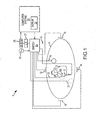
- FIG. 1 presents a schematic of one embodiment of a medical navigation/visualization system 5.
- the medical navigation/visualization system 5 will be briefly addressed herein, as it is one such system that may utilize the mapping electrode functionality that will be addressed in detail below.
- the medical navigation/visualization system 5 is also discussed in detail in U.S. Patent Application Publication No. US 2004/0254437 (published on Dec. 16, 2004 ) that is assigned to the assigned of this patent application.
- the patient 11 is only schematically depicted as an oval for clarity.
- Three sets of surface or patch electrodes are shown as 18, 19 along a Y-axis; as 12, 14 along an X-axis; and 16, 22 along a Z-axis.
- Patch electrode 16 is shown on the surface closest to the observer, and patch electrode 22 is shown in outline form to show its placement on the back of patient 11.
- An additional patch electrode which may be referred to as a "belly" patch, is also seen in the figure as patch electrode 21.
- Each patch electrode 18, 19, 12, 14, 16, 22, 21 is independently connected to a multiplex switch 24.
- the heart 10 of patient 11 lies between these various sets of patch electrodes 18, 19 12, 14, 16, 22.
- a representative catheter 13 having a number of electrodes 17.
- the electrodes 17 may be referred to as the "roving electrodes" or “measurement electrodes” herein. It is noted that any number of electrodes may be utilized, generally with more electrodes providing higher-density mapping. It is also noted that in use the patient 11 will have most or all of the conventional 12 lead ECG system in place as well, and this ECG information is available to the system even though it is not illustrated in the figures.
- Each patch electrode 18, 19, 12, 14, 16, 22, 21 is coupled to the switch 24, and pairs of electrodes 18, 19, 12, 14, 16, 22 are selected by software running on computer system 20, which couples these electrodes 18, 19, 12, 14, 16, 22 to the signal generator 25.
- a pair of electrodes, for example electrodes 18 and 19, may be excited by the signal generator 25 and they generate a field in the body of the patient and the heart 10.
- the remaining patch electrodes 12, 14, 16, 22 are referenced to the belly patch electrode 21, and the voltages impressed on these remaining electrodes 12, 14, 16, 22 are measured by the analog-to-digital or A-to-D converter 26.
- Suitable lowpass filtering of the digital data may be subsequently performed in software to remove electronic noise and cardiac motion artifact after suitable low pass filtering in filter 27.
- the various patch electrodes 18, 19, 12, 14, 16, 22 are divided into driven and non-driven electrode sets. While a pair of electrodes is driven by the signal generator 25, the remaining non-driven electrodes are used as references to synthesize the orthogonal drive axes.
- the belly patch electrode 21 is seen in the figure is an alternative to a fixed intra-cardiac electrode.
- a coronary sinus electrode or other fixed electrode in the heart 10 can be used as a reference for measuring voltages and displacements.
- All of the raw patch voltage data is measured by the A-to-D converter 26 and stored in the computer system 20 under the direction of software.
- This electrode excitation process occurs rapidly and sequentially as alternate sets of patch electrodes 18, 19, 12, 14, 16, 22 are selected, and the remaining members of the set are used to measure voltages.
- This collection of voltage measurements may be referred to herein as the "patch data set".
- the software has access to each individual voltage measurement made at each individual patch electrode 18, 19, 12, 14, 16, 22 during each excitation of each pair of electrodes 18, 19, 12, 14, 16, 22.
- the raw patch data is used to determine the "raw" location in three spaces (X, Y, Z) of the electrodes inside the heart 10, such as the roving electrodes 17.
- This process is also referred to as "triangulation.”
- Triangulation is the process of determining the location of a point by measuring angles from known points.
- Optical three-dimensional measuring systems use triangulation networks in order to determine spatial dimensions and the geometry.
- Output of at least two of the sensors are considered the point on an object's surface which define a spatial triangle. Within this triangle, the distance between the sensors is the base and is known.
- the intersection point, and thus the 3d coordinate is calculated from the triangular relations.
- the roving electrodes 17 are swept around in the heart chamber while the heart 10 is beating, a large number of electrode locations are collected. These data points are taken at all stages of the heartbeat and without regard to the cardiac phase. Since the heart 10 changes shape during contraction, only a small number of the points represent the maximum heart volume. By selecting the most exterior points, it is possible to create a "shell" representing the shape of the heart 10.
- the location attribute of the electrodes within the heart 10 are measured while the electric field is impressed on the heart 10 by the surface patch electrodes 18, 19, 12,14, 16, 22.
- the patch data set may also be used to create a respiration compensation value to improve the raw location data for the locations of the electrodes 18, 19, 12, 14, 16, 22 due to movement of the patient's body (e.g., during breathing).
- FIG. 2 shows a catheter 13, which may be a high-density mapping catheter, as described in more detail below, in the heart 10.
- the catheter 13 has a tip electrode 51 (and may optionally include additional electrodes, not visible in the figures). Since these electrodes lie in the heart 10, the location process detects their location in the heart 10. While they lay on the surface and when the signal generator 25 is "off", each patch electrode 18, 19, 12, 14, 16, 22 ( FIG. 1 ) can be used to measure the voltage on the heart surface. The magnitude of this voltage, as well as the timing relationship of the signal with respect to the heartbeat events, may be measured and presented to the cardiologist or technician through the display 23.
- the peak-to-peak voltage measured at a particular location on the heart wall is capable of showing areas of diminished conductivity, and which may reflect an infracted region of the heart 10.
- the timing relationship data are typically displayed as "isochrones". In essence, regions that receive the depolarization waveform at the same time are shown in the same false color or gray scale.
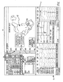
- FIG. 3 shows an illustrative computer display from the computer system 20.
- the display 23 is used to show data to the physician user and to present certain options that allow the user to tailor the system configuration for a particular use. It should be noted that the contents on the display 23 can be easily modified and the specific data presented is only of a representative nature.
- An image panel 60 shows a geometry of the heart chamber 62 that shows "isochrones" in false color or grayscale together with guide bar 64 to assist in interpretation. In this hypothetical image, the noted mapping methodology has been used with a high-density catheter to create a chamber representation that is displayed as a contoured image.
- the guide bar 64 is graduated in milliseconds and it shows the assignment of time relationship for the false color image in the geometry.
- the relationship between the false color on the geometry image 62 and the guide bar 64 is defined by interaction with the user in panel 66.
- the display may also provide traces and other information related to the ECG electrodes, mapping electrodes and reference electrodes, as well as other information that may assist the physicians.
- a high density mapping electrode catheter may be implemented having a plurality of electrodes.
- An exemplary catheter 100 is shown in FIG. 4 .
- the illustrated catheter 100 includes a catheter body or shaft 102 having an electrode tip 108 disposed at a distal end thereof.
- the catheter 100 further includes a number of mapping electrode wires 104 terminating in electrodes 106.
- the electrodes 106 can be used to map cardiac tissue, as discussed above. More specifically, a physician can sweep the electrodes 106 across tissue to be mapped. In this regard, a large volume of mapping information can be obtained quickly when the electrodes 106 come into contact with the tissue as the catheter 100 is swept across the tissue.
- Each of the wires 104 may be threaded through an inner lumen of the catheter shaft 102.
- the electrodes 106 then extend through holes formed in the catheter shaft 102 at the desired location.
- the electrodes 106 may be bonded to the shaft 102 at the openings or may otherwise be maintained in a substantially fixed relationship with respect to the shaft 102.
- the electrodes 106 may be tightly secured to catheter shaft 102.
- each of the mapping electrodes may be formed from a nickel titanium fiber with a conductive metallic core such as platinum.
- the conductive core of the illustrated fibers serves as the electrical pathway for the tip electrodes 106 (instead of the wires 104).
- the tip electrodes 106 may be formed by melting an exposed section of the conductive core near the surface of the catheter shaft 102.
- the catheter shaft 102 will have a diameter and stiffness that is significantly greater than the diameter and stiffness of the wiring 104 provided therein.
- the catheter shaft 102 may be a 5 or 7 French (i,e., 0.065 in. or 0.092 in.) catheter.
- the catheter shaft may have a diameter that is at least five to ten times (or more) the diameter of the individual wires 104.
- the size of the catheter shaft 102 may allow the catheter shaft 102 to readily deflect when the moved (e.g., brushed) over an internal tissue surface without significant deflection of the catheter shaft 102.
- the catheter shaft may have a buckle strength (e.g., where bending is initiated) of no more than about 5 grams and more preferably no more than about 1-2 grams.
- a buckle strength e.g., where bending is initiated
- Use of such low buckling strength allows the end of the catheter shaft 102 to readily conform to a tissue surface without significantly deflecting or otherwise penetrating the tissue surface.
- the stiffness of the shaft alerts an operator (e.g., physician) that the catheter shaft is in contact with patient tissue.
- the inner lumen of the catheter shaft 102 may be used to thread the wiring 104 for the electrodes 106.
- a lumen for such irrigation fluid may be formed within catheter shaft 102 (which can include openings to allow for flow of the irrigation fluid), or the irrigation fluid may be delivered via a separate lumen associated with other structure of the catheter.
- This tip configuration has a number of advantages. First, it is desirable to avoid puncturing of the cardiac tissue in connection with contact by the catheter.
- the enlarged and rounded configuration of the tip in this regard provides a larger surface contact area and reduces the pressure on and likelihood of puncturing any cardiac tissue contacted.
- the enlarged tip improves impedance and, therefore, visibility with respect to the electrical navigation system.
- the increased cross-section also improves visibility with respect to the fluoroscopic images.
- the electrodes 106 can be any of various types of electrodes including ablation electrodes, mapping electrodes, or combination ablation/mapping electrodes.
- the illustrated electrodes 106 are mapping electrodes, as best shown in FIG. 4 .
- the electrodes 106 are divided into a number of electrically isolated sections 110, in this case, defining four quadrants. Because the sections 110 are electrically isolated, independent positioning signals can be obtained with regard to each of the sections 110. In this manner the signals from the sections 110 can be processed to define references, e.g., North, South, East and West, which are useful in guiding movement of the catheter during a medical procedure.
- FIG. 5 is a block diagram illustrating an exemplary embodiment of computer components and program code which may be implemented in accordance with the present invention to process the positional or mapping data from the electrodes 106.
- the mapping data obtained by the electrodes 106 may be processed using software 200 executable on a computer system (e.g., the computer system 20 shown in FIG. 1 ).
- the software 200 may include a rendering component 201 and an enhancement component 202, each operatively associated with an output device (e.g., the display 23 in FIG. 1 ) and computer readable storage 210.
- the processing component 201 receives raw data from the electrodes 106 and generates a plurality of images based on the raw data.
- the rendering component 201 may overlay the data images on one another to generate a three-dimensional image representing both the internal tissue and an unobstructed portion of the catheter body. Exemplary output is illustrated in FIG. 6A-C , and discussed in more detail below.
- the enhancement component 202 overlays a silhouette of what would otherwise be an obstructed portion of the catheter body 102 using the positional data for the catheter body 102 (e.g., as can be seen in FIG. 6A-C ). Operation of the enhancement component 202 may be described as including two tasks. First, the enhancement component 202 generates candidate silhouette fragments, and second the enhancement component 202 displays only those candidate fragments that are obscured or obstructed by other objects in the scene output on the display 23.
- the first task may be accomplished using the same triangulation data that are used to produce the three-dimensional image of the catheter (e.g., as used by the processing component 201).
- the triangles are joined edge-to-edge to form a closed volume that approximates very closely the true shape of the body of the catheter.
- Candidate silhouette fragments are those edges shared between two triangles, one with its outward side pointing toward the physician field of view, and the other with its outward side pointing away from the physician's field of view.
- Each of the candidate edges may be compiled into a list 211 for further processing. Additional edges may be added in special cases.
- One such special case may include when the edge separates a catheter electrode 106 from the catheter body 102 and at least one of the adjacent triangles has an outward side pointing toward the physician's field of view.
- Another such case may include when the edge is at the end of the catheter body 102 and the end plane has its outward side pointing toward the physician's field of view.
- Another such case may include when the edge is at the end of the catheter body 102 and the adjacent triangle has its outward side pointing toward the physician's field of view.
- the second task may be accomplished by applying a graphics depth buffer 212.
- Each edge in the list of candidate silhouette fragments is first offset away from the center of the catheter body 102 by a distance in the model space corresponding to one pixel on the display 23. This avoids the possibility of the edge being obscured by the same catheter body 102 that generated the edge.
- the edge is then drawn into a frame buffer 213 using a depth mask that allows drawing of a pixel only if the depth is greater than the current depth.
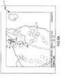
- FIG. 6A-C illustrate exemplary images 250a-c which may be output on a display provided by the navigation and mapping system, such as the display 23 shown in FIG. 1 and 3 .
- a graphical rendering of the catheter 100 includes both an unobstructed portion 252a-c (respectively in FIG. 6A-C ) and portion 255a-c of the catheter 100 that would otherwise be obstructed from view (e.g., behind the heart wall). Accordingly, the physician is able to view an image of the entire length of the catheter 100 which is within the area being displayed.
- both the unobstructed portions 252a-c (respectively) of the catheter 100, and the obstructed portion(s) 255a-c are shown (i.e., those portions 255a-c are visible in the 3-D images 250a-c that would otherwise be obstructed by the heart wall).
- the portion of the catheter 100 that would otherwise be obstructed by the heart wall may be identified by the enhancement component by comparing a depth coordinate of the catheter 100 to a depth coordinate of the surface of the heart 10, and then overlaying silhouettes 255a-c representing the obstructed portion(s) of the catheter 100 only when the depth coordinate of the catheter 100 is greater than the depth coordinate for the surface of the heart 10.
- FIG. 6B and 6C it is further seen that more than one catheter 100 and 100' is shown in the 3-D images 250a-c.
- the rendering of the obstructed portion(s) 255b, 255c are shown for the active catheter (i.e., the catheter that the physician is currently moving).
- a graphical rendering may be shown for the obstructed portion(s) of more than one of the catheters (e.g., for both catheters 100 and 100').
- the unobstructed portions 252a-c of the catheters are shown as being shaded so as to appear as a three-dimensional object, and the obstructed portions 252a-c are shown as silhouettes or outlines.
- any suitable differentiation may be used, such as but not limited to, different colors or different shading for the portions 252a-c and 255a-c.
- the output may be updated in real-time or substantially in real-time. Accordingly, the physician is able to view the images 250a-c as the catheter 100 is being moved and positioned at the desired location within the heart 10.
- FIG. 7 is a flow diagram illustrating exemplary operations which may be implemented in accordance with the present invention.
- Operations 300 may be embodied as logic instructions on one or more computer-readable medium. When executed on a processor, the logic instructions cause a general purpose computing device to be programmed as a special-purpose machine that implements the described operations.
- the components and connections depicted in the figures may be used for brokering creative content online.
- Operations 300 illustrate an exemplary method for mapping cardiac tissue and modeling an obstructed view of an electrode catheter.
- mapping coordinates are obtained from an electrode catheter inserted into a chamber of a heart, where the mapping coordinates representing a surface of the heart.
- a three-dimensional image is generated based on the mapping information, where the three-dimensional images shows the surface of the heart and an unobstructed portion of the electrode catheter.
- a plurality of candidate silhouette fragments is generated representing a body of the electrode catheter.
- a determination is made which candidate silhouette fragments are obstructed by other visible objects in the three-dimensional image.
- the obstructed portion of the electrode catheter is overlaid on the three-dimensional image using only those candidate silhouette fragments determined to be obstructed by other visible objects in the three-dimensional image.
Landscapes
- Health & Medical Sciences (AREA)
- Life Sciences & Earth Sciences (AREA)
- Engineering & Computer Science (AREA)
- Medical Informatics (AREA)
- Molecular Biology (AREA)
- General Health & Medical Sciences (AREA)
- Biophysics (AREA)
- Biomedical Technology (AREA)
- Heart & Thoracic Surgery (AREA)
- Physics & Mathematics (AREA)
- Veterinary Medicine (AREA)
- Surgery (AREA)
- Animal Behavior & Ethology (AREA)
- Pathology (AREA)
- Public Health (AREA)
- Human Computer Interaction (AREA)
- Nuclear Medicine, Radiotherapy & Molecular Imaging (AREA)
- Radiology & Medical Imaging (AREA)
- Cardiology (AREA)
- Gynecology & Obstetrics (AREA)
- High Energy & Nuclear Physics (AREA)
- Optics & Photonics (AREA)
- Measurement And Recording Of Electrical Phenomena And Electrical Characteristics Of The Living Body (AREA)
Claims (7)
- Système de cartographie électrique pour tissu interne, le système de cartographie électrique modélisant les parties obstruée et non-obstruée d'un cathéter (100, 100'), comprenant :un corps (102) de cathéter comprenant une partie distale et une partie proximale, le corps (102) de cathéter supportant une pluralité d'électrodes (106) connectées électriquement à un dispositif (20) de sortie; etun composant (201) de rendu associé de façon opérative avec le dispositif (20) de sortie, le composant (201) de rendu recevant des données brutes de la pluralité d'électrodes (106) et générant une pluralité d'images sur base des données brutes, le composant (201) de rendu superposant la pluralité d'images de données l'une sur l'autre pour générer une image tridimensionnelle représentant le tissu interne et une partie visible du corps (102) de cathéter;un composant (202) d'amplification configuré pour superposer une silhouette sur l'image tridimensionnelle, la silhouette représentant au moins une partie obstruée du corps (102) de cathéter en utilisant les données de position pour le corps (102) de cathéter,caractérisé en ce que le composant (202) d'amplification génère des fragments de silhouette candidats et montre seulement ceux des fragments de silhouette candidats obstrués par d'autres objets visibles.
- Système selon la revendication 1, dans lequel d'autres objets visibles incluent des parties (252a, 255a) du tissu interne; ou
dans lequel d'autres objets visibles incluent des graphiques d'affichage; ou
dans lequel d'autres objets visibles incluent des étiquettes, des lésions, des marqueurs anatomiques, et d'autres cathéters (100, 100'). - Système selon la revendication 1 ou 2, dans lequel le composant (202) d'amplification superpose une silhouette sur l'image tridimensionnelle de l'au moins une partie obstruée d'une pluralité de cathéters.
- Système selon l'une quelconque des revendications 1 à 3, dans lequel le composant (202) d'amplification illustre de façon graphique au moins une partie (255a) obstruée d'un cathéter (100, 100') actif.
- Système selon l'une quelconque des revendications 1 à 4, dans lequel le composant (202) d'amplification illustre de façon graphique une limite extérieure de l'au moins une partie (255a) obstruée du corps (102) de cathéter.
- Système selon l'une quelconque des revendications 1 à 5, dans lequel le composant (202) d'amplification utilise des données de triangulation utilisées par le composant (201) de rendu.
- Système selon l'une quelconque des revendications 1 à 6, dans lequel le composant (202) d'amplification applique un tampon (212) de profondeur pour identifier une limite extérieure de l'au moins une partie (255a) obstruée du corps (102) de cathéter;
dans lequel préférablement le composant (202) d'amplification dessine seulement la limite extérieure de l'au moins une partie (255a) obstruée du corps (102) de cathéter si une coordonnée de profondeur du corps (102) de cathéter est plus grande qu'une coordonnée de profondeur pour le tissu interne qui est montré.
Applications Claiming Priority (2)
| Application Number | Priority Date | Filing Date | Title |
|---|---|---|---|
| US1413507P | 2007-12-17 | 2007-12-17 | |
| PCT/US2008/087269 WO2009079602A1 (fr) | 2007-12-17 | 2008-12-17 | Systèmes et procédés destinés à façonner des portions à la fois non obstruées et obstruées d'un cathéter |
Publications (3)
| Publication Number | Publication Date |
|---|---|
| EP2197347A1 EP2197347A1 (fr) | 2010-06-23 |
| EP2197347A4 EP2197347A4 (fr) | 2011-11-30 |
| EP2197347B1 true EP2197347B1 (fr) | 2015-06-24 |
Family
ID=40795918
Family Applications (1)
| Application Number | Title | Priority Date | Filing Date |
|---|---|---|---|
| EP08861396.3A Active EP2197347B1 (fr) | 2007-12-17 | 2008-12-17 | Systèmes et procédés destinés à façonner des portions à la fois non obstruées et obstruées d'un cathéter |
Country Status (3)
| Country | Link |
|---|---|
| US (2) | US8352019B2 (fr) |
| EP (1) | EP2197347B1 (fr) |
| WO (1) | WO2009079602A1 (fr) |
Families Citing this family (34)
| Publication number | Priority date | Publication date | Assignee | Title |
|---|---|---|---|---|
| US9119633B2 (en) | 2006-06-28 | 2015-09-01 | Kardium Inc. | Apparatus and method for intra-cardiac mapping and ablation |
| US11389232B2 (en) | 2006-06-28 | 2022-07-19 | Kardium Inc. | Apparatus and method for intra-cardiac mapping and ablation |
| US8906011B2 (en) | 2007-11-16 | 2014-12-09 | Kardium Inc. | Medical device for use in bodily lumens, for example an atrium |
| US9582934B2 (en) * | 2010-09-20 | 2017-02-28 | Siemens Healthcare Gmbh | Method and system for efficient extraction of a silhouette of a 3D mesh |
| US9999399B2 (en) | 2010-11-16 | 2018-06-19 | Siemens Healthcare Gmbh | Method and system for pigtail catheter motion prediction |
| US9014423B2 (en) | 2011-03-14 | 2015-04-21 | Siemens Aktiengesellschaft | Method and system for catheter tracking in fluoroscopic images using adaptive discriminant learning and measurement fusion |
| US9424648B2 (en) | 2011-07-07 | 2016-08-23 | Siemens Aktiengesellschaft | Method and system for device detection in 2D medical images |
| US9011423B2 (en) | 2012-05-21 | 2015-04-21 | Kardium, Inc. | Systems and methods for selecting, activating, or selecting and activating transducers |
| US9198592B2 (en) | 2012-05-21 | 2015-12-01 | Kardium Inc. | Systems and methods for activating transducers |
| US10827977B2 (en) | 2012-05-21 | 2020-11-10 | Kardium Inc. | Systems and methods for activating transducers |
| US9026196B2 (en) * | 2013-03-05 | 2015-05-05 | St. Jude Medical, Atrial Fibrillation Division, Inc. | System and method for detecting sheathing and unsheathing of localization elements |
| CN105917389B (zh) * | 2014-03-21 | 2018-10-30 | 圣犹达医疗用品心脏病学部门有限公司 | 用于生成几何结构的多维表面模型的方法和系统 |
| US9615764B2 (en) * | 2014-11-03 | 2017-04-11 | Biosense Webster (Israel) Ltd | Real-time coloring of electrophysiological map |
| US10368936B2 (en) | 2014-11-17 | 2019-08-06 | Kardium Inc. | Systems and methods for selecting, activating, or selecting and activating transducers |
| US10722184B2 (en) | 2014-11-17 | 2020-07-28 | Kardium Inc. | Systems and methods for selecting, activating, or selecting and activating transducers |
| RU2017140233A (ru) | 2015-05-12 | 2019-06-13 | Навикс Интернэшнл Лимитед | Оценка качества контакта посредством анализа диэлектрических свойств |
| EP3294127A1 (fr) | 2015-05-12 | 2018-03-21 | Navix International Limited | Systèmes et procédés de suivi d'un cathéter intracorps |
| RU2017140235A (ru) | 2015-05-12 | 2019-06-13 | Навикс Интернэшнл Лимитед | Оценка очагов поражения посредством анализа диэлектрических свойств |
| WO2016181320A1 (fr) | 2015-05-12 | 2016-11-17 | Navix International Limited | Marquage de repère pour mise en coïncidence d'image-champ électromagnétique |
| US20170231580A1 (en) * | 2016-02-16 | 2017-08-17 | St. Jude Medical, Cardiology Division, Inc. | Methods and Systems for Electrophysiology Mapping Using Medical Images |
| US11350996B2 (en) | 2016-07-14 | 2022-06-07 | Navix International Limited | Characteristic track catheter navigation |
| US11382566B1 (en) | 2016-11-21 | 2022-07-12 | Walter Kusumoto | Lead placement assisted by electrophysiology mapping |
| US11007016B2 (en) | 2016-09-22 | 2021-05-18 | Walter Kusumoto | Intracardiac ultrasound catheter handheld adapter |
| US10973436B2 (en) | 2016-09-22 | 2021-04-13 | Walter Kusumoto | Pericardiocentesis needle guided by cardiac electrophysiology mapping |
| WO2018092063A1 (fr) | 2016-11-16 | 2018-05-24 | Navix International Limited | Affichage en temps réel de changements de tissu liés au traitement à l'aide d'un matériau virtuel |
| US11284813B2 (en) | 2016-11-16 | 2022-03-29 | Navix International Limited | Real-time display of tissue deformation by interactions with an intra-body probe |
| CN110198680B (zh) | 2016-11-16 | 2022-09-13 | 纳维斯国际有限公司 | 消融有效性估计器 |
| CN110177500B (zh) | 2016-11-16 | 2022-03-04 | 纳维斯国际有限公司 | 组织模型动态视觉渲染 |
| CN110072449B (zh) | 2016-11-16 | 2023-02-24 | 纳维斯国际有限公司 | 通过电标测进行的食道位置检测 |
| US11406451B2 (en) | 2018-02-27 | 2022-08-09 | Walter Kusumoto | Ultrasound thermometry for esophageal or other tissue protection during ablation |
| WO2020163940A1 (fr) | 2019-02-14 | 2020-08-20 | Kardium Inc. | Systèmes et procédés de navigation de cathéter |
| WO2020171998A2 (fr) | 2019-02-21 | 2020-08-27 | St. Jude Medical, Cardiology Division, Inc. | Systèmes et méthodes pour évaluer des lésions d'ablation |
| US11998287B1 (en) | 2019-03-18 | 2024-06-04 | Dopl Technologies Inc. | Platform for facilitating remote robotic medical procedures |
| EP4427681A1 (fr) | 2023-03-09 | 2024-09-11 | St. Jude Medical, Cardiology Division, Inc. | Guidage pour la navigation et le positionnement de dispositifs distribués par voie intravasculaire |
Family Cites Families (12)
| Publication number | Priority date | Publication date | Assignee | Title |
|---|---|---|---|---|
| US5662108A (en) * | 1992-09-23 | 1997-09-02 | Endocardial Solutions, Inc. | Electrophysiology mapping system |
| US6603996B1 (en) * | 2000-06-07 | 2003-08-05 | Graydon Ernest Beatty | Software for mapping potential distribution of a heart chamber |
| US5297549A (en) * | 1992-09-23 | 1994-03-29 | Endocardial Therapeutics, Inc. | Endocardial mapping system |
| US5687737A (en) * | 1992-10-09 | 1997-11-18 | Washington University | Computerized three-dimensional cardiac mapping with interactive visual displays |
| US5391199A (en) * | 1993-07-20 | 1995-02-21 | Biosense, Inc. | Apparatus and method for treating cardiac arrhythmias |
| US5697377A (en) * | 1995-11-22 | 1997-12-16 | Medtronic, Inc. | Catheter mapping system and method |
| US6050267A (en) * | 1997-04-28 | 2000-04-18 | American Cardiac Ablation Co. Inc. | Catheter positioning system |
| US7263397B2 (en) | 1998-06-30 | 2007-08-28 | St. Jude Medical, Atrial Fibrillation Division, Inc. | Method and apparatus for catheter navigation and location and mapping in the heart |
| US6892091B1 (en) * | 2000-02-18 | 2005-05-10 | Biosense, Inc. | Catheter, method and apparatus for generating an electrical map of a chamber of the heart |
| US6650927B1 (en) * | 2000-08-18 | 2003-11-18 | Biosense, Inc. | Rendering of diagnostic imaging data on a three-dimensional map |
| US7505810B2 (en) * | 2006-06-13 | 2009-03-17 | Rhythmia Medical, Inc. | Non-contact cardiac mapping, including preprocessing |
| US7729752B2 (en) * | 2006-06-13 | 2010-06-01 | Rhythmia Medical, Inc. | Non-contact cardiac mapping, including resolution map |
-
2008
- 2008-12-17 US US12/743,629 patent/US8352019B2/en active Active
- 2008-12-17 WO PCT/US2008/087269 patent/WO2009079602A1/fr not_active Ceased
- 2008-12-17 EP EP08861396.3A patent/EP2197347B1/fr active Active
-
2012
- 2012-12-10 US US13/710,156 patent/US8825144B2/en active Active
Also Published As
| Publication number | Publication date |
|---|---|
| US20140005528A1 (en) | 2014-01-02 |
| US8352019B2 (en) | 2013-01-08 |
| US8825144B2 (en) | 2014-09-02 |
| EP2197347A4 (fr) | 2011-11-30 |
| US20100249579A1 (en) | 2010-09-30 |
| WO2009079602A1 (fr) | 2009-06-25 |
| EP2197347A1 (fr) | 2010-06-23 |
| WO2009079602A9 (fr) | 2010-09-10 |
Similar Documents
| Publication | Publication Date | Title |
|---|---|---|
| EP2197347B1 (fr) | Systèmes et procédés destinés à façonner des portions à la fois non obstruées et obstruées d'un cathéter | |
| US10657715B2 (en) | Systems and methods for visualizing and analyzing cardiac arrhythmias using 2-D planar projection and partially unfolded surface mapping processes | |
| AU2017254839B2 (en) | Selectably transparent electrophysiology map | |
| US9307931B2 (en) | Multiple shell construction to emulate chamber contraction with a mapping system | |
| CA2355788C (fr) | Methode et appareil de cartographie d'une cavite cardiaque | |
| CN1874735B (zh) | 对电生理导管的心脏应用提供可视化支持的方法和装置 | |
| US20080228060A1 (en) | High density mapping catheter | |
| AU2012203967B2 (en) | Cardiac mapping using non-gated MRI | |
| US20150228254A1 (en) | Systems and Methods for Generating, Storing, and Displaying Anatomical Maps | |
| US10714218B2 (en) | Methods and systems for displaying electrophysiological lesions |
Legal Events
| Date | Code | Title | Description |
|---|---|---|---|
| PUAI | Public reference made under article 153(3) epc to a published international application that has entered the european phase |
Free format text: ORIGINAL CODE: 0009012 |
|
| 17P | Request for examination filed |
Effective date: 20100330 |
|
| AK | Designated contracting states |
Kind code of ref document: A1 Designated state(s): AT BE BG CH CY CZ DE DK EE ES FI FR GB GR HR HU IE IS IT LI LT LU LV MC MT NL NO PL PT RO SE SI SK TR |
|
| AX | Request for extension of the european patent |
Extension state: AL BA MK RS |
|
| RAP1 | Party data changed (applicant data changed or rights of an application transferred) |
Owner name: ST. JUDE MEDICAL, ATRIAL FIBRILLATION DIVISION, IN |
|
| DAX | Request for extension of the european patent (deleted) | ||
| A4 | Supplementary search report drawn up and despatched |
Effective date: 20111031 |
|
| RIC1 | Information provided on ipc code assigned before grant |
Ipc: A61B 5/042 20060101AFI20111025BHEP |
|
| 17Q | First examination report despatched |
Effective date: 20140731 |
|
| GRAP | Despatch of communication of intention to grant a patent |
Free format text: ORIGINAL CODE: EPIDOSNIGR1 |
|
| INTG | Intention to grant announced |
Effective date: 20150312 |
|
| GRAS | Grant fee paid |
Free format text: ORIGINAL CODE: EPIDOSNIGR3 |
|
| GRAA | (expected) grant |
Free format text: ORIGINAL CODE: 0009210 |
|
| AK | Designated contracting states |
Kind code of ref document: B1 Designated state(s): AT BE BG CH CY CZ DE DK EE ES FI FR GB GR HR HU IE IS IT LI LT LU LV MC MT NL NO PL PT RO SE SI SK TR |
|
| REG | Reference to a national code |
Ref country code: GB Ref legal event code: FG4D |
|
| REG | Reference to a national code |
Ref country code: CH Ref legal event code: EP |
|
| REG | Reference to a national code |
Ref country code: AT Ref legal event code: REF Ref document number: 732554 Country of ref document: AT Kind code of ref document: T Effective date: 20150715 |
|
| REG | Reference to a national code |
Ref country code: IE Ref legal event code: FG4D |
|
| REG | Reference to a national code |
Ref country code: DE Ref legal event code: R096 Ref document number: 602008038726 Country of ref document: DE |
|
| PG25 | Lapsed in a contracting state [announced via postgrant information from national office to epo] |
Ref country code: FI Free format text: LAPSE BECAUSE OF FAILURE TO SUBMIT A TRANSLATION OF THE DESCRIPTION OR TO PAY THE FEE WITHIN THE PRESCRIBED TIME-LIMIT Effective date: 20150624 Ref country code: HR Free format text: LAPSE BECAUSE OF FAILURE TO SUBMIT A TRANSLATION OF THE DESCRIPTION OR TO PAY THE FEE WITHIN THE PRESCRIBED TIME-LIMIT Effective date: 20150624 Ref country code: LT Free format text: LAPSE BECAUSE OF FAILURE TO SUBMIT A TRANSLATION OF THE DESCRIPTION OR TO PAY THE FEE WITHIN THE PRESCRIBED TIME-LIMIT Effective date: 20150624 Ref country code: NO Free format text: LAPSE BECAUSE OF FAILURE TO SUBMIT A TRANSLATION OF THE DESCRIPTION OR TO PAY THE FEE WITHIN THE PRESCRIBED TIME-LIMIT Effective date: 20150924 |
|
| REG | Reference to a national code |
Ref country code: AT Ref legal event code: MK05 Ref document number: 732554 Country of ref document: AT Kind code of ref document: T Effective date: 20150624 |
|
| REG | Reference to a national code |
Ref country code: LT Ref legal event code: MG4D |
|
| PG25 | Lapsed in a contracting state [announced via postgrant information from national office to epo] |
Ref country code: GR Free format text: LAPSE BECAUSE OF FAILURE TO SUBMIT A TRANSLATION OF THE DESCRIPTION OR TO PAY THE FEE WITHIN THE PRESCRIBED TIME-LIMIT Effective date: 20150925 Ref country code: LV Free format text: LAPSE BECAUSE OF FAILURE TO SUBMIT A TRANSLATION OF THE DESCRIPTION OR TO PAY THE FEE WITHIN THE PRESCRIBED TIME-LIMIT Effective date: 20150624 Ref country code: BG Free format text: LAPSE BECAUSE OF FAILURE TO SUBMIT A TRANSLATION OF THE DESCRIPTION OR TO PAY THE FEE WITHIN THE PRESCRIBED TIME-LIMIT Effective date: 20150924 |
|
| REG | Reference to a national code |
Ref country code: NL Ref legal event code: MP Effective date: 20150624 |
|
| REG | Reference to a national code |
Ref country code: FR Ref legal event code: PLFP Year of fee payment: 8 |
|
| PG25 | Lapsed in a contracting state [announced via postgrant information from national office to epo] |
Ref country code: EE Free format text: LAPSE BECAUSE OF FAILURE TO SUBMIT A TRANSLATION OF THE DESCRIPTION OR TO PAY THE FEE WITHIN THE PRESCRIBED TIME-LIMIT Effective date: 20150624 |
|
| PG25 | Lapsed in a contracting state [announced via postgrant information from national office to epo] |
Ref country code: SK Free format text: LAPSE BECAUSE OF FAILURE TO SUBMIT A TRANSLATION OF THE DESCRIPTION OR TO PAY THE FEE WITHIN THE PRESCRIBED TIME-LIMIT Effective date: 20150624 Ref country code: CZ Free format text: LAPSE BECAUSE OF FAILURE TO SUBMIT A TRANSLATION OF THE DESCRIPTION OR TO PAY THE FEE WITHIN THE PRESCRIBED TIME-LIMIT Effective date: 20150624 Ref country code: ES Free format text: LAPSE BECAUSE OF FAILURE TO SUBMIT A TRANSLATION OF THE DESCRIPTION OR TO PAY THE FEE WITHIN THE PRESCRIBED TIME-LIMIT Effective date: 20150624 Ref country code: AT Free format text: LAPSE BECAUSE OF FAILURE TO SUBMIT A TRANSLATION OF THE DESCRIPTION OR TO PAY THE FEE WITHIN THE PRESCRIBED TIME-LIMIT Effective date: 20150624 Ref country code: RO Free format text: LAPSE BECAUSE OF NON-PAYMENT OF DUE FEES Effective date: 20150624 Ref country code: IS Free format text: LAPSE BECAUSE OF FAILURE TO SUBMIT A TRANSLATION OF THE DESCRIPTION OR TO PAY THE FEE WITHIN THE PRESCRIBED TIME-LIMIT Effective date: 20151024 Ref country code: PT Free format text: LAPSE BECAUSE OF FAILURE TO SUBMIT A TRANSLATION OF THE DESCRIPTION OR TO PAY THE FEE WITHIN THE PRESCRIBED TIME-LIMIT Effective date: 20151026 Ref country code: PL Free format text: LAPSE BECAUSE OF FAILURE TO SUBMIT A TRANSLATION OF THE DESCRIPTION OR TO PAY THE FEE WITHIN THE PRESCRIBED TIME-LIMIT Effective date: 20150624 |
|
| REG | Reference to a national code |
Ref country code: DE Ref legal event code: R097 Ref document number: 602008038726 Country of ref document: DE |
|
| PG25 | Lapsed in a contracting state [announced via postgrant information from national office to epo] |
Ref country code: DK Free format text: LAPSE BECAUSE OF FAILURE TO SUBMIT A TRANSLATION OF THE DESCRIPTION OR TO PAY THE FEE WITHIN THE PRESCRIBED TIME-LIMIT Effective date: 20150624 |
|
| PLBE | No opposition filed within time limit |
Free format text: ORIGINAL CODE: 0009261 |
|
| STAA | Information on the status of an ep patent application or granted ep patent |
Free format text: STATUS: NO OPPOSITION FILED WITHIN TIME LIMIT |
|
| PG25 | Lapsed in a contracting state [announced via postgrant information from national office to epo] |
Ref country code: BE Free format text: LAPSE BECAUSE OF NON-PAYMENT OF DUE FEES Effective date: 20151231 |
|
| 26N | No opposition filed |
Effective date: 20160329 |
|
| PG25 | Lapsed in a contracting state [announced via postgrant information from national office to epo] |
Ref country code: LU Free format text: LAPSE BECAUSE OF FAILURE TO SUBMIT A TRANSLATION OF THE DESCRIPTION OR TO PAY THE FEE WITHIN THE PRESCRIBED TIME-LIMIT Effective date: 20151217 Ref country code: MC Free format text: LAPSE BECAUSE OF FAILURE TO SUBMIT A TRANSLATION OF THE DESCRIPTION OR TO PAY THE FEE WITHIN THE PRESCRIBED TIME-LIMIT Effective date: 20150624 |
|
| REG | Reference to a national code |
Ref country code: CH Ref legal event code: PL |
|
| PG25 | Lapsed in a contracting state [announced via postgrant information from national office to epo] |
Ref country code: SI Free format text: LAPSE BECAUSE OF FAILURE TO SUBMIT A TRANSLATION OF THE DESCRIPTION OR TO PAY THE FEE WITHIN THE PRESCRIBED TIME-LIMIT Effective date: 20150624 |
|
| REG | Reference to a national code |
Ref country code: IE Ref legal event code: MM4A |
|
| PG25 | Lapsed in a contracting state [announced via postgrant information from national office to epo] |
Ref country code: CH Free format text: LAPSE BECAUSE OF NON-PAYMENT OF DUE FEES Effective date: 20151231 Ref country code: LI Free format text: LAPSE BECAUSE OF NON-PAYMENT OF DUE FEES Effective date: 20151231 Ref country code: IE Free format text: LAPSE BECAUSE OF NON-PAYMENT OF DUE FEES Effective date: 20151217 |
|
| REG | Reference to a national code |
Ref country code: FR Ref legal event code: PLFP Year of fee payment: 9 |
|
| PG25 | Lapsed in a contracting state [announced via postgrant information from national office to epo] |
Ref country code: BE Free format text: LAPSE BECAUSE OF FAILURE TO SUBMIT A TRANSLATION OF THE DESCRIPTION OR TO PAY THE FEE WITHIN THE PRESCRIBED TIME-LIMIT Effective date: 20150624 |
|
| PG25 | Lapsed in a contracting state [announced via postgrant information from national office to epo] |
Ref country code: IT Free format text: LAPSE BECAUSE OF NON-PAYMENT OF DUE FEES Effective date: 20151217 |
|
| PG25 | Lapsed in a contracting state [announced via postgrant information from national office to epo] |
Ref country code: HU Free format text: LAPSE BECAUSE OF FAILURE TO SUBMIT A TRANSLATION OF THE DESCRIPTION OR TO PAY THE FEE WITHIN THE PRESCRIBED TIME-LIMIT; INVALID AB INITIO Effective date: 20081217 |
|
| PG25 | Lapsed in a contracting state [announced via postgrant information from national office to epo] |
Ref country code: NL Free format text: LAPSE BECAUSE OF FAILURE TO SUBMIT A TRANSLATION OF THE DESCRIPTION OR TO PAY THE FEE WITHIN THE PRESCRIBED TIME-LIMIT Effective date: 20150624 Ref country code: CY Free format text: LAPSE BECAUSE OF FAILURE TO SUBMIT A TRANSLATION OF THE DESCRIPTION OR TO PAY THE FEE WITHIN THE PRESCRIBED TIME-LIMIT Effective date: 20150624 Ref country code: SE Free format text: LAPSE BECAUSE OF FAILURE TO SUBMIT A TRANSLATION OF THE DESCRIPTION OR TO PAY THE FEE WITHIN THE PRESCRIBED TIME-LIMIT Effective date: 20150624 |
|
| PG25 | Lapsed in a contracting state [announced via postgrant information from national office to epo] |
Ref country code: MT Free format text: LAPSE BECAUSE OF FAILURE TO SUBMIT A TRANSLATION OF THE DESCRIPTION OR TO PAY THE FEE WITHIN THE PRESCRIBED TIME-LIMIT Effective date: 20150624 Ref country code: TR Free format text: LAPSE BECAUSE OF FAILURE TO SUBMIT A TRANSLATION OF THE DESCRIPTION OR TO PAY THE FEE WITHIN THE PRESCRIBED TIME-LIMIT Effective date: 20150624 Ref country code: IT Free format text: LAPSE BECAUSE OF NON-PAYMENT OF DUE FEES Effective date: 20151217 |
|
| PGRI | Patent reinstated in contracting state [announced from national office to epo] |
Ref country code: IT Effective date: 20170710 |
|
| REG | Reference to a national code |
Ref country code: FR Ref legal event code: PLFP Year of fee payment: 10 |
|
| REG | Reference to a national code |
Ref country code: DE Ref legal event code: R079 Ref document number: 602008038726 Country of ref document: DE Free format text: PREVIOUS MAIN CLASS: A61B0005042000 Ipc: A61B0005283000 |
|
| P01 | Opt-out of the competence of the unified patent court (upc) registered |
Effective date: 20230616 |
|
| REG | Reference to a national code |
Ref country code: DE Ref legal event code: R082 Ref document number: 602008038726 Country of ref document: DE Representative=s name: ALPSPITZ IP ALLGAYER UND PARTNER PATENTANWAELT, DE |
|
| PGFP | Annual fee paid to national office [announced via postgrant information from national office to epo] |
Ref country code: DE Payment date: 20251118 Year of fee payment: 18 |
|
| PGFP | Annual fee paid to national office [announced via postgrant information from national office to epo] |
Ref country code: GB Payment date: 20251113 Year of fee payment: 18 |
|
| PGFP | Annual fee paid to national office [announced via postgrant information from national office to epo] |
Ref country code: IT Payment date: 20251212 Year of fee payment: 18 |
|
| PGFP | Annual fee paid to national office [announced via postgrant information from national office to epo] |
Ref country code: FR Payment date: 20251111 Year of fee payment: 18 |