EP2197348B1 - Mehrfrequenz-überwachungssystem - Google Patents
Mehrfrequenz-überwachungssystem Download PDFInfo
- Publication number
- EP2197348B1 EP2197348B1 EP09739383.9A EP09739383A EP2197348B1 EP 2197348 B1 EP2197348 B1 EP 2197348B1 EP 09739383 A EP09739383 A EP 09739383A EP 2197348 B1 EP2197348 B1 EP 2197348B1
- Authority
- EP
- European Patent Office
- Prior art keywords
- impedance
- lead
- electrodes
- phase angle
- measured
- Prior art date
- Legal status (The legal status is an assumption and is not a legal conclusion. Google has not performed a legal analysis and makes no representation as to the accuracy of the status listed.)
- Active
Links
Images


Classifications
-
- A—HUMAN NECESSITIES
- A61—MEDICAL OR VETERINARY SCIENCE; HYGIENE
- A61B—DIAGNOSIS; SURGERY; IDENTIFICATION
- A61B5/00—Measuring for diagnostic purposes; Identification of persons
- A61B5/05—Detecting, measuring or recording for diagnosis by means of electric currents or magnetic fields; Measuring using microwaves or radio waves
- A61B5/053—Measuring electrical impedance or conductance of a portion of the body
-
- A—HUMAN NECESSITIES
- A61—MEDICAL OR VETERINARY SCIENCE; HYGIENE
- A61B—DIAGNOSIS; SURGERY; IDENTIFICATION
- A61B5/00—Measuring for diagnostic purposes; Identification of persons
- A61B5/08—Measuring devices for evaluating the respiratory organs
- A61B5/085—Measuring impedance of respiratory organs or lung elasticity
- A61B5/086—Measuring impedance of respiratory organs or lung elasticity by impedance pneumography
-
- A—HUMAN NECESSITIES
- A61—MEDICAL OR VETERINARY SCIENCE; HYGIENE
- A61B—DIAGNOSIS; SURGERY; IDENTIFICATION
- A61B5/00—Measuring for diagnostic purposes; Identification of persons
- A61B5/05—Detecting, measuring or recording for diagnosis by means of electric currents or magnetic fields; Measuring using microwaves or radio waves
- A61B5/053—Measuring electrical impedance or conductance of a portion of the body
- A61B5/0538—Measuring electrical impedance or conductance of a portion of the body invasively, e.g. using a catheter
-
- A—HUMAN NECESSITIES
- A61—MEDICAL OR VETERINARY SCIENCE; HYGIENE
- A61B—DIAGNOSIS; SURGERY; IDENTIFICATION
- A61B5/00—Measuring for diagnostic purposes; Identification of persons
- A61B5/48—Other medical applications
- A61B5/4869—Determining body composition
-
- A—HUMAN NECESSITIES
- A61—MEDICAL OR VETERINARY SCIENCE; HYGIENE
- A61B—DIAGNOSIS; SURGERY; IDENTIFICATION
- A61B5/00—Measuring for diagnostic purposes; Identification of persons
- A61B5/68—Arrangements of detecting, measuring or recording means, e.g. sensors, in relation to patient
- A61B5/6846—Arrangements of detecting, measuring or recording means, e.g. sensors, in relation to patient specially adapted to be brought in contact with an internal body part, i.e. invasive
- A61B5/6847—Arrangements of detecting, measuring or recording means, e.g. sensors, in relation to patient specially adapted to be brought in contact with an internal body part, i.e. invasive mounted on an invasive device
- A61B5/686—Permanently implanted devices, e.g. pacemakers, other stimulators, biochips
-
- A—HUMAN NECESSITIES
- A61—MEDICAL OR VETERINARY SCIENCE; HYGIENE
- A61B—DIAGNOSIS; SURGERY; IDENTIFICATION
- A61B5/00—Measuring for diagnostic purposes; Identification of persons
- A61B5/72—Signal processing specially adapted for physiological signals or for diagnostic purposes
- A61B5/7235—Details of waveform analysis
- A61B5/7253—Details of waveform analysis characterised by using transforms
- A61B5/7257—Details of waveform analysis characterised by using transforms using Fourier transforms
-
- A—HUMAN NECESSITIES
- A61—MEDICAL OR VETERINARY SCIENCE; HYGIENE
- A61N—ELECTROTHERAPY; MAGNETOTHERAPY; RADIATION THERAPY; ULTRASOUND THERAPY
- A61N1/00—Electrotherapy; Circuits therefor
- A61N1/18—Applying electric currents by contact electrodes
- A61N1/32—Applying electric currents by contact electrodes alternating or intermittent currents
- A61N1/36—Applying electric currents by contact electrodes alternating or intermittent currents for stimulation
- A61N1/362—Heart stimulators
- A61N1/365—Heart stimulators controlled by a physiological parameter, e.g. heart potential
- A61N1/36514—Heart stimulators controlled by a physiological parameter, e.g. heart potential controlled by a physiological quantity other than heart potential, e.g. blood pressure
- A61N1/36521—Heart stimulators controlled by a physiological parameter, e.g. heart potential controlled by a physiological quantity other than heart potential, e.g. blood pressure the parameter being derived from measurement of an electrical impedance
Definitions
- the present invention relates to systems for measuring intrathoracic impedance (intracardiac, intravascular, subcutaneous, etc.) in an implantable medical device (IMD) system.
- IMD implantable medical device
- Intrathoracic impedance measuring is performed by monitoring the voltage differential between pairs of spaced electrodes as current pulses are injected into those same leads or into other electrodes. Changes in the measured intrathoracic impedance may indicate certain disease conditions that can be addressed by delivery of therapy or alarm notification, for example.
- the efficacy of impedance monitoring to evaluate and monitor pulmonary edema and worsening congestive heart failure has been demonstrated in the OptiVol® Fluid Status Monitoring system provided by Medtronic, Inc. of Minneapolis, MN
- a system is provided to measure intrathoracic impedance and to identify and monitor disease conditions based on the impedance measurements. Multiple electrode combinations may be taken into account, and an optimal combination of electrodes may be selected to provide the most useful (e.g., sensitive and specific) impedance measurement for the identification and monitoring of disease conditions.
- FIG. 1 is a diagram depicting path 20 taken by low frequency current injected through a selected tissue segment T, and path 22 taken by high frequency current injected through tissue segment T.
- Low frequency current flows primarily in path 20 through extracellular spaces in tissue segment T, due to the frequency dependent resistance provided by the cellular membrane of cells C.
- high frequency current reduces the capacitive reactance component of the cellular membrane of cells C, allowing current to flow more uniformly through tissue segment T. This difference in the response of tissue segment T to currents of different frequencies can be utilized to identify and predict disease conditions, examples of which are discussed in detail below.
- FIG. 2 is a diagram illustrating an example of the relative placement of IMD 30 and lead 32 carrying electrodes 34 for performing an intrathoracic impedance measurement.
- IMD 30 is implantable under the skin of a patient in the chest area, and includes impedance measurement circuitry and processing circuitry, as well as various leads for sensing and therapy delivery functions.
- lead 32 is shown extending into the right ventricle (RV), with electrodes 34 positioned in the RV, the right atrium, the superior vena cava and the subclavian vein. By injecting a current between selected electrodes 34, a voltage differential between those electrodes can be created that allows the impedance of the tissue between the electrodes to be measured.
- RV right ventricle
- FIG. 3 is a graph illustrating the magnitude of the impedance measured between electrodes in a tissue segment (such as between selected electrodes 34 shown in FIG. 2 ) for a low frequency injection current (curve 40) and a high frequency injection current (curve 42).
- low frequency current flows primarily through extracellular spaces in tissue
- high frequency current reduces the capacitivc reactance component of the cellular membranes, allowing current to flow more uniformly through the tissue.
- the impedance measured in response to the low frequency injection current is larger than the impedance measured in response to the high frequency injection current.
- the difference 44 between the low frequency impedance and the high frequency impedance of the tissue is indicative of the state of the tissue.
- the progression of pulmonary edema causes the difference between the low frequency impedance magnitude and the high frequency impedance magnitude to decrease, due to the accumulation of fluid in the extracellular spaces.
- measurement of the magnitudes of impedance in response to a low frequency injection current and to a high frequency injection current, and calculating the difference between the impedance magnitudes can produce an indicator of disease such as heart failure, pulmonary edema, or others.
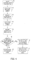
- FIG. 4 is a flow diagram illustrating an example of a method of monitoring the difference between impedance magnitudes at low and high injection current frequencies.
- a low frequency current is injected into an electrode pair (step 51), and the magnitude of the impedance (Z L ) at low frequency is measured (step 52).
- a high frequency current is injected into the electrode pair (step 54), and the magnitude of the impedance (Z H ) at high frequency is measured (step 56).
- the low frequency impedance (Z L ) is then compared to the high frequency impedance (Z H ) (step 58).
- the low frequency impedance (Z L ) is significantly greater than the high frequency impedance (Z H )
- conditions are normal and there is no indication of heart failure or pulmonary edema (step 60).
- the difference between the low frequency impedance (Z L ) and the high frequency impedance (Z H ) is evaluated to determine the state of the tissue (step 62). From this evaluation, the onset and progression of disease such as heart failure or pulmonary edema is indicated (step 64).
- a smaller difference between the low frequency impedance (Z L ) and the high frequency impedance (Z H ) may indicate a more advanced progression of heart failure or, more specifically, pulmonary edema.
- the low frequency is no greater than about 10 kiloHertz
- the high frequency is about ten times greater than the low frequency, such as between about 50 kiloHertz and 100 kiloHertz.
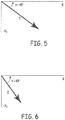
- FIGS. 5 and 6 are exemplary phasor diagrams illustrating the real component (R) and the reactive component (X C ) of impedance (Z), measured in response to a low frequency injection current in healthy tissue ( FIG. 5 ) and in diseased tissue having fluid accumulated in extracellular spaces ( FIG. 6 ).
- the accumulation of fluid in extracellular spaces results in an increase in the phase angle ( ⁇ ) of the impedance phasor (such as from 45° for healthy tissue in FIG. 5 to 60° for diseased tissue in the example of FIG. 6 ), and also in a decrease in the total magnitude of impedance (Z), due to a decrease in the real component (R) of impedance caused by a decrease in the extracellular volumes of the cells, which causes the cells' extracellular resistance to decrease.
- the increase in phase angle or the decrease in impedance magnitude (or both) is detectable as an indication of the onset or progression of cardiopulmonary disease such as pulmonary edema secondary to heart failure.
- FIG. 7 is a flow diagram illustrating an example of a method of monitoring changes in phase angle and/or impedance magnitude in response to low frequency injection current in order to detect pulmonary edema.
- a low frequency current is injected into an electrode pair (step 71), and the magnitude and phase angle of the impedance is measured (step 72).
- the magnitude of the impedance is then compared to a reference value (step 74), and it is determined whether the magnitude of the impedance has decreased from the reference value (step 76). If the impedance has decreased from the reference value, the onset/progression of pulmonary edema and the like is indicated (step 78).
- the next step is to compare the phase angle of the impedance to a reference value (step 80), and to determine whether the phase angle has increased from the reference value (step 82), which would indicate that the real component of the impedance has decreased in comparison to the reactive component of the impedance (see FIGS. 5 and 6 ). If the phase angle of the impedance has not increased from the reference value, there is no indication of pulmonary edema (step 84). If the phase angle of the impedance has increased from the reference value, the onset/progression of pulmonary edema is indicated (step 86).
- a method according to FIG. 7 shows separate determinations of the onset/progression of pulmonary edema based on the magnitude and the phase angle of impedance.
- a determination of either a decreased magnitude of impedance or an increased phase angle of impedance will result in an indication of the onset/progression of pulmonary edema.
- both a decrease in the magnitude of impedance and an increase in the phase angle of impedance are required to indicate the onset/progression of pulmonary edema.
- separate indications of the onset/progression of pulmonary edema based on a relative change in the magnitude of impedance and the phase angle of impedance are provided.
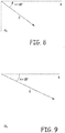
- FIGS. 8 and 9 are phasor diagrams illustrating the real component (R) and the reactive component (X C ) of impedance (Z), measured in response to a high frequency injection current in healthy tissue ( FIG. 8 ) and in diseased tissue such as in myocardial ischemia ( FIG. 9 ).
- the impedance (Z) and phase angle ( ⁇ ) are calculated according to Eq. 1 and Eq. 2 above, respectively.
- ischemia in the tissue results in a decrease in the phase angle ( ⁇ ) of the impedance phasor (such as from 45° for healthy tissue in FIG. 8 to 35° for ischemic tissue in FIG.
- FIG. 10 is a flow diagram illustrating an example of a method of monitoring changes in phase angle and/or impedance magnitude in response to high frequency injection current in order to detect disease such as myocardial ischemia.
- a high frequency current is injected into an electrode pair (step 91), and the magnitude and phase angle of the impedance is measured (step 92).
- the magnitude of the impedance is then compared to a reference value (step 94), and it is determined whether the magnitude of the impedance has increased from the reference value (step 96). If the impedance has increased from the reference value, an indication of tissue ischemia is made (step 98).
- the next step is to compare the phase angle of the impedance to a reference value (step 100), and to determine whether the phase angle has decreased from the reference value (step 102), which would indicate that the resistive component of the impedance has increased in comparison to the reactive component of the impedance (see FIGS. 8 and 9 ). If the phase angle of the impedance has not decreased from the reference value, there is no indication of tissue ischemia (step 104). If the phase angle of the impedance has decreased from the reference value, an indication of tissue ischemia is made (step 106).
- a method according to FIG. 10 shows separate determinations of tissue ischemia based on the magnitude and the phase angle of impedance.
- a determination of either an increased magnitude of impedance or a decreased phase angle of impedance will result in an indication of tissue ischemia.
- both an increase in the magnitude of impedance and a decrease in the phase angle of impedance are required to indicate tissue ischemia.
- separate indications of tissue ischemia based on a relative change in the magnitude of impedance and the phase angle of impedance are provided.
- FIG. 2 illustrates an example of the relative placement of IMD 30 and lead 32 carrying electrodes 34 for performing an intrathoracic impedance measurement, with lead 32 extending into the right ventricle (RV), and electrodes 34 positioned in the RV, the right atrium, the superior vena cava and the subclavian vein.
- RV right ventricle
- FIGS. 11A-11D show examples of how electrodes 34 may be used in this configuration.
- FIG. 11A illustrates a scenario in which a stimulation vector (S) is established between an electrode in the right atrium (RA) and an electrode in the RV, so that transvalvular impedance can be measured by voltage sense vectors (VS).
- FIG. 11B illustrates a scenario in which a stimulation vector (S) is established between an electrode adjacent to IMD 30 and an electrode in the RV, so that left heart impedance can be measured by voltage sense vectors (VS).
- FIG. 11C illustrates a scenario in which a stimulation vector (S) is established between an electrode in the superior vena cava and an electrode in the RV, so that right heart impedance can be measured by a voltage sense vector (VS).
- FIG. 11D illustrates a scenario in which a stimulation vector (S) is established between an electrode adjacent to IMD 30 and an electrode in the superior vena cava, so that superior lung impedance can be measured by a voltage sense vector (
- FIG. 12 illustrates another example of the relative placement of IMD 30 and lead 32 carrying electrodes 34 for performing an intrathoracic impedance measurement, with the distal end of lead 32 placed over the left ventricle (LV) via the cardiac vein, and electrodes 34 positioned over the LV, in the right atrium, and in the subclavian vein.
- FIGS. 13A-13D show examples of how electrodes 34 may be used in this configuration.
- FIG. 13A illustrates a scenario in which a stimulation vector (S) is established between two electrodes spanning the LV, so that LV impedance can be measured by voltage sense vectors (VS).
- S stimulation vector
- VS voltage sense vectors
- FIG. 13B illustrates a scenario in which a stimulation vector (S) is established between a distal electrode adjacent the LV and an electrode in the right atrium (RA), so that right atrial impedance can be measured by voltage sense vectors (VS).
- FIG. 13C illustrates a scenario in which a stimulation vector (S) is established between a distal electrode adjacent the LV and an electrode adjacent IMD 30, so that left lung impedance can be measured by voltage sense vectors (VS).
- FIG. 13D illustrates a scenario in which a stimulation vector (S) is established between an electrode in the RA and an electrode adjacent IMD 30, so that superior left lung impedance can be measured by voltage sense vectors (VS).
- Lead 32 may alternatively be positioned to provide electrodes 34 epicardially over the LV to allow similar measurements.
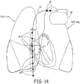
- FIG. 14 illustrates another example of the relative placement of IMD 30 and lead 32 carrying electrodes 34 for performing an intrathoracic impedance measurement, with the distal end of lead 32 placed in the inferior vena cava (IVC), and electrodes 34 positioned in the IVC, right atrium, superior vena cava and subclavian vein.
- FIGS. 15A-15D show examples of how electrodes 34 may be used in this configuration.
- FIG. 15A illustrates a scenario in which a stimulation vector (S) is established between two electrodes spanning the IVC, so that IVC impedance can be measured by a voltage sense vector (VS).
- S stimulation vector
- VS voltage sense vector
- FIG. 15B illustrates a scenario in which a stimulation vector (S) is established between an electrode in the RA and an electrode in the superior vena cava, so that superior vena cava impedance can be measured by a voltage sense vector (VS).
- FIG. 15C illustrates a scenario in which a stimulation vector (S) is established between an electrode in the IVC and an electrode in the superior vena cava, so that central venous impedance can be measured by a voltage sense vector (VS).
- FIG. 15D illustrates a scenario in which a stimulation vector (S) is established between an electrode in the IVC and an electrode in adjacent to IMD 30, so that atrial impedance can be measured by a voltage sensor vector (VS).
- FIG. 16 illustrates another example of the relative placement of IMD 30 carrying electrodes 34 and lead 32 carrying electrodes 34 for performing an intrathoracic impedance measurement, with electrodes 34 carried by the housing (or “can") of IMD 30 implanted subcutaneously in the left lateral superior thorax, with a distal end of lead 32 placed over the left ventricle (LV) via the cardiac vein, and with electrodes 34 carried by lead 32 positioned over the LV, in the right atrium (RA), and in the subclavian vein.
- FIGS. 17A-17C show examples of how electrodes 34 maybe used in this configuration.
- FIG. 17A illustrates a scenario in which a stimulation vector (S) is established between an electrode in the RA and an electrode carried by the housing of IMD 30, so that upper lung impedance or RA function can be measured by voltage sense vectors (VS).
- FIG. 17B illustrates a scenario in which a stimulation vector (S) is established between an electrode in the posterior coronary sinus or applicable cardiac vein and an electrode carried by the housing of IMD 30, so that middle lung impedance can be measured by voltage sense vectors (VS).
- FIG. 17C illustrates a scenario in which a stimulation vector (S) is established between a distal electrode in the subclavian vein adjacent the LV and an electrode carried by the housing of IMD 30, so that lower lung impedance can be measured by voltage sense vectors (VS).
- FIG. 18 illustrates an example of subcutaneous lead 112 configured with its distal end (carrying electrodes 114) placed in the left lateral thorax.
- lead 112 When lead 112 is used in conjunction with intrathoracic lead 32 and electrodes 34, left heart and left lung zones can be isolated for impedance measurements.
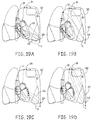
- FIGS. 19A and 19B show examples of how electrodes 34 and 114 may be used in this configuration, where lead 32 and electrodes 34 are arranged as shown in FIG. 2 .
- FIG. 19A illustrates a scenario in which a stimulation vector (S) is established between an electrode in the RV and the distal electrode in the left lateral thorax, so that left heart and inferior left lung impedance can be measured by voltage sense vectors (VS).
- S stimulation vector
- VS voltage sense vectors
- FIG. 19B illustrates a scenario in which a stimulation vector (S) is established between an electrode in the superior vena cava and the distal electrode in the left lateral thorax, so that left lung impedance can be measured by voltage sense vectors (VS).
- FIGS. 19C and 19D show examples of how electrodes 34 and 114 may be used where lead 32 and electrodes 34 are arranged as shown in FIG. 12 .
- FIG. 19C illustrates a scenario in which a stimulation vector (S) is established between an electrode adjacent the LV and the distal electrode in the left lateral thorax, so that lower left lung impedance can be measured by a voltage sense vector (VS).
- FIG. 19D illustrates a scenario in which a stimulation vector (S) is established between an electrode in the upper left lung and the distal electrode in the left lateral thorax, so that upper left lung impedance can be measured by a voltage sense vector (VS).
- S stimulation vector
- VS voltage sense vector
- the impedance waveforms measured via the electrode configurations discussed above contain a high frequency cardiac component superimposed on a low frequency respiratory component and a calculated DC or mean component.
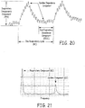
- FIG. 20 is a diagram illustrating an example of such an impedance waveform.
- Each of the components of the impedance waveform has potential clinical diagnostic utility (for example, diagnostics for detecting various conditions are discussed above).
- the relative magnitude of each component of the impedance waveform depends on the geometric electrode configuration.
- the ratio of the magnitude of the cardiac impedance component to the magnitude of the respiratory impedance component (CC/RC) is analyzed for each vector, and the vector having the highest CC/RC ratio is selected as the most useful for analysis of the impedance waveform for the selected tissue segment.
- Geometric vector configurations may be selected to identify the most useful electrode vector for diagnostic monitoring of the lung for fluid accumulation and respiration, the myocardium for ischemia, or the cardiac chambers for contractility, stroke volume, dilation, or arrhythmia identification.
- the measurement of impedances in these regions is useful to measure fluid compartmentalization shifts in patients with congestive heart failure or pulmonary edema, or to isolate a specific section of the myocardium to detect ischemia, for example.
- a detailed discussion of analyzing the morphology of various components of complex impedance waveforms to determine changes in physiologic parameters that may indicate the onset or progression of various clinical conditions may be found in U.S. Application No.
- the impedance waveform shown in FIG. 20 may be obtained from a subcutaneous, intracardiac, or combination thereof electrode vector configuration. Two positive pressure ventilation (PPV) respiratory cycles are shown. Parameters illustrated in FIG. 20 include a respiratory cycle (RC) time, an end expiratory impedance component (EEIC) time, and an inspiratory impedance component (labeled as PPV). Cardiac impedance components appear as high frequency components of the waveform.
- RC respiratory cycle
- EEIC end expiratory impedance component
- PPV inspiratory impedance component
- FIG 21 is a diagram illustrating a Fast Fourier Transform (FFT) analysis of the impedance waveform shown in FIG. 20 .
- FFT Fast Fourier Transform
- the high frequency cardiac component (CC) of the impedance waveform is easily visible and separated from the low frequency respiratory component (RC) of the impedance waveform.
- a FFT analysis is one example of a method that can be used to calculate the ratio of the magnitude of the high frequency CC of impedance to the low frequency RC of impedance, to identify an electrode vector having the highest CC/RC ratio for selection to analyze and identify certain physiological conditions and disease states.
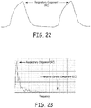
- FIG. 22 is a diagram illustrating an example of an impedance waveform obtained from a transthoracic subcutaneous electrode vector configuration utilizing electrodes positioned substernal and bilateral on the left and right thorax.
- the impedance waveform has a highly attenuated high frequency cardiac component (CC), such that only the low frequency respiratory component (RC) of the impedance waveform is even observable.
- FIG. 23 is a diagram illustrating a Fast Fourier Transform (FFT) analysis of the impedance waveform shown in FIG. 22 .
- FFT Fast Fourier Transform
- the high frequency CC of the impedance waveform is attenuated and not observable, while the low frequency RC of the impedance waveform is easily observable.
- the CC/RC ratio in this scenario is low, and this electrode vector would typically not be selected for analysis in order to determine physiological conditions and disease states.
- FIG. 24 is a diagram illustrating an example of an impedance waveform obtained from a combination subcutaneous and intracardiac electrode vector configuration utilizing electrodes positioned in the right ventricle, the left ventricle, and the device housing.
- the impedance waveform has a significant, observable high frequency cardiac component (CC), and a relatively small low frequency respiratory component (RC) of the impedance waveform is observable.
- FIG. 25 is a diagram illustrating a Fast Fourier Transform (FFT) analysis of the impedance waveform shown in FIG. 24 .
- FFT Fast Fourier Transform
- the high frequency CC of the impedance waveform is significant and easily observable, separated from the relatively small low frequency RC of the impedance waveform.
- the CC/RC ratio in this scenario is high, and this electrode vector would highly likely to be selected for analysis in order to determine physiological conditions and disease states.
- FIG. 26 is a diagram illustrating a method of calculating a CC/RC ratio of an impedance waveform utilizing a threshold adjustment technique.
- the peak impedance of the RC of the impedance waveform is detected and measured during end inspiration, and the peak impedance of the CC of the impedance waveform is detected and measured during end expiration.
- This method is performed as shown in the flowchart of FIG. 27 .
- the mean of the impedance waveform is detected over a programmable time period, such as fifteen seconds in one embodiment (step 120).
- the detected mean is then set as a first threshold (Z A , see FIG. 26 ; step 122).
- a peak detection algorithm determines the frequency of the peak impedances (step 124) and identifies whether the determined frequency is within the limits of normal breathing rates (such as below 40 breaths per minute in one example; step 126).
- the peak impedance of the RC is then recorded (Z RC , see FIG. 26 ; step 128). Once this peak is determined, the mean impedance is divided by two (Z 1/2 , see FIG. 26 ; step 130). Then the peak detection algorithm is again performed to determine the frequency of the peak impedances below Z 1/2 (step 132).
- the algorithm identifies whether the determined frequency is within the limits of normal cardiac rates (such as above 50 beats per minute in one example; step 134), and if it is not, the threshold is again divided by two (step 136) and the process is repeated. Once a valid frequency is determined, the peak impedance of the CC (Z CC ) is recorded (step 138). These impedance magnitudes for each vector are then used to determine the optimal electrode vector configuration based on the Z CC Z RC ratio of each vector (step 140).
- the system(s) and method(s) described above provide an improved ability to measure complex intrathoracic impedance and to identify and predict disease conditions based on the impedance measurements. Multiple impedance vectors may be taken into account, and an optimal vector may be selected to provide the most useful impedance measurement for the identification and prediction of disease conditions.
Landscapes
- Health & Medical Sciences (AREA)
- Life Sciences & Earth Sciences (AREA)
- Heart & Thoracic Surgery (AREA)
- Engineering & Computer Science (AREA)
- Veterinary Medicine (AREA)
- Physics & Mathematics (AREA)
- Biomedical Technology (AREA)
- Biophysics (AREA)
- Animal Behavior & Ethology (AREA)
- General Health & Medical Sciences (AREA)
- Public Health (AREA)
- Surgery (AREA)
- Molecular Biology (AREA)
- Medical Informatics (AREA)
- Pathology (AREA)
- Radiology & Medical Imaging (AREA)
- Nuclear Medicine, Radiotherapy & Molecular Imaging (AREA)
- Cardiology (AREA)
- Physiology (AREA)
- Hematology (AREA)
- Mathematical Physics (AREA)
- Artificial Intelligence (AREA)
- Computer Vision & Pattern Recognition (AREA)
- Psychiatry (AREA)
- Signal Processing (AREA)
- Pulmonology (AREA)
- Measurement And Recording Of Electrical Phenomena And Electrical Characteristics Of The Living Body (AREA)
- Electrotherapy Devices (AREA)
Claims (11)
- System zum Messen einer intrathorakalen Impedanz über mehrere ausgewählte Gewebesegmente hinweg, das Folgendes umfasst:eine Leitung (32), die mehrere Elektroden (34) trägt, wobei die Elektroden auf der Leitung so positioniert sind, dass in Verwendung ausgewählte Paare der Elektroden ausgewählte der mehreren ausgewählten Gewebesegmente überspannen;Mittel zum Einspeisen eines Niederfrequenzstroms zwischen den ausgewählten Elektrodenpaaren;Impedanzmessschaltungen, die konfiguriert sind, um eine Impedanzgröße und einen Impedanzphasenwinkel zwischen den ausgewählten Elektrodenpaaren zu messen, um gemessene Impedanzgrößen und Phasenwinkel für die ausgewählten Elektrodenpaare der Niederfrequenz zu erzeugen; undVerarbeitungsschaltungen, die konfiguriert sind, um die gemessenen Impedanzen zu bewerten, um zu bestimmen, ob sich das Gewebesegment in einem erkrankten Zustand befindet, und um ein Kennzeichen für eine Erkrankung basierend auf der Bestimmung bereitzustellen, ob sich das Gewebesegment in einem erkrankten Zustand befindet, wobei die Verarbeitungsschaltungen Mittel zum Vergleichen der gemessenen Impedanzgröße und/oder des gemessenen Impedanzphasenwinkels bei der Niederfrequenz mit einem Referenzwert der Impedanzgröße beziehungsweise einem Referenzwert des Impedanzphasenwinkels umfassen, die bei der Niederfrequenz festgelegt sind;Mittel zum Bewerten einer Abnahme der Impedanzgröße von dem Referenzwert und/oder einer Zunahme des Impedanzphasenwinkels von dem Referenzwert, um zu bestimmen, ob sich das Gewebesegment in einem erkrankten Zustand befindet; undMittel zum Bereitstellen einesKennzeichens für eine Erkrankung basierend auf der Bestimmung, ob sich das Gewebe in einem erkrankten Zustand befindet; und wobeiein Kennzeichen für ein Lungenödem basierend auf der Zunahme des gemessenen Impedanzphasenwinkels von dem Referenzwert des Impedanzphasenwinkels bereitgestellt wird.
- System nach Anspruch 1, wobei die Leitung mit einer implantierbaren medizinischen Vorrichtung (implantable medical device - IMD) verbunden ist, die die Impedanzmessschaltungen und die Verarbeitungsschaltungen umhaust.
- System nach Anspruch 2, wobei die IMD wenigstens eine Elektrode umfasst.
- System nach Anspruch 3, wobei wenigstens ein Abschnitt der Leitung angeordnet ist, um in Verwendung über einem linken Ventrikel über eine Herzvene oder epikardial positioniert zu sein, und die Elektroden durch die wenigstens eine Leitung derart getragen werden, dass sie in Verwendung in der Herzvene über dem linken Ventrikel, epikardial über dem linken Ventrikel, einem rechten Vorhof und/oder einer Vena subclavia positioniert sind.
- System nach Anspruch 1, wobei wenigstens ein Abschnitt der Leitung angeordnet ist, um in einem rechten Ventrikel positioniert zu sein, und die Elektroden durch die wenigstens eine Leitung derart getragen werden, dass sie in Verwendung in dem rechten Ventrikel, einem rechten Vorhof, einer oberen Hohlvene und/oder einer Vena subclavia positioniert sind.
- System nach Anspruch 1, wobei wenigstens ein Abschnitt der Leitung angeordnet ist, um über einem linken Ventrikel über eine Herzvene positioniert zu sein, und die Elektroden durch die wenigstens eine Leitung derart getragen werden, dass sie in Verwendung in der Herzvene über dem linken Ventrikel, einem rechten Vorhof und/oder einer Vena subclavia positioniert sind.
- System nach Anspruch 1, wobei wenigstens ein Abschnitt der Leitung angeordnet ist, um in einer unteren Hohlvene positioniert zu sein, und die Elektroden durch die wenigstens eine Leitung derart getragen werden, dass sie in Verwendung in der unteren Hohlvene, einem rechten Vorhof, einer oberen Hohlvene und/oder einer Vena subclavia positioniert sind.
- System nach Anspruch 1, wobei die Leitung eine erste Leitung beinhaltet, die in einem linken seitlichen Thorax positioniert ist, und Elektroden durch die erste Leitung derart getragen werden, dass sie in Verwendung in dem linken seitlichen Thorax positioniert sind.
- System nach Anspruch 8, wobei die wenigstens eine Leitung ferner eine zweite Leitung beinhaltet, die angeordnet ist, um in Verwendung wenigstens teilweise in einem rechten Ventrikel positioniert zu sein, und Elektroden durch die zweite Leitung derart getragen werden, dass sie in Verwendung in dem rechten Ventrikel, einem rechten Vorhof, einer oberen Hohlvene und/oder einer Vena subclavia positioniert sind.
- System nach Anspruch 8, wobei die wenigstens eine Leitung ferner eine zweite Leitung beinhaltet, die angeordnet ist, um in Verwendung über einem linken Ventrikel über eine Herzvene wenigstens teilweise positioniert zu sein, und Elektroden durch die zweite Leitung derart getragen werden, dass sie in Verwendung in der Herzvene über dem linken Ventrikel, epikardial über dem linken Ventrikel, einem rechten Vorhof und/oder einer Vena subclavia positioniert sind.
- System nach Anspruch 1, das Mittel zum Auswählen eines Paares der ausgewählten Elektrodenpaare für eine Bewertung der Impedanzmessung dazwischen basierend auf einer Bestimmung, dass ein Verhältnis zwischen einer Impedanzherzkomponente und einer Impedanzatmungskomponente unter den ausgewählten Elektrodenpaaren am größten ist, beinhaltet.
Applications Claiming Priority (2)
| Application Number | Priority Date | Filing Date | Title |
|---|---|---|---|
| US12/112,765 US8744565B2 (en) | 2008-04-30 | 2008-04-30 | Multi-frequency impedance monitoring system |
| PCT/US2009/039314 WO2009134581A1 (en) | 2008-04-30 | 2009-04-02 | Multi-frequency impedance monitoring system |
Publications (2)
| Publication Number | Publication Date |
|---|---|
| EP2197348A1 EP2197348A1 (de) | 2010-06-23 |
| EP2197348B1 true EP2197348B1 (de) | 2021-03-10 |
Family
ID=40678930
Family Applications (1)
| Application Number | Title | Priority Date | Filing Date |
|---|---|---|---|
| EP09739383.9A Active EP2197348B1 (de) | 2008-04-30 | 2009-04-02 | Mehrfrequenz-überwachungssystem |
Country Status (3)
| Country | Link |
|---|---|
| US (3) | US8744565B2 (de) |
| EP (1) | EP2197348B1 (de) |
| WO (1) | WO2009134581A1 (de) |
Families Citing this family (23)
| Publication number | Priority date | Publication date | Assignee | Title |
|---|---|---|---|---|
| CA2608962C (en) | 2005-07-01 | 2016-12-06 | Scott Chetham | Monitoring system |
| AU2006265763B2 (en) | 2005-07-01 | 2012-08-09 | Impedimed Limited | Monitoring system |
| WO2007041783A1 (en) | 2005-10-11 | 2007-04-19 | Impedance Cardiology Systems, Inc. | Hydration status monitoring |
| EP2148613B9 (de) | 2007-04-20 | 2014-12-10 | Impedimed Limited | Überwachungssystem und sonde |
| EP2175776B1 (de) | 2007-08-09 | 2016-03-23 | Impedimed Limited | Impedanz-messverfahren |
| US8744565B2 (en) | 2008-04-30 | 2014-06-03 | Medtronic, Inc. | Multi-frequency impedance monitoring system |
| US8684920B2 (en) * | 2008-07-07 | 2014-04-01 | Medtronic, Inc. | Classification of severity of medical condition by wavelet based multi-resolution analysis |
| US9713701B2 (en) | 2008-07-31 | 2017-07-25 | Medtronic, Inc. | Using multiple diagnostic parameters for predicting heart failure events |
| US9370654B2 (en) * | 2009-01-27 | 2016-06-21 | Medtronic, Inc. | High frequency stimulation to block laryngeal stimulation during vagal nerve stimulation |
| WO2011050393A1 (en) | 2009-10-26 | 2011-05-05 | Impedimed Limited | Fluid level indicator determination |
| WO2011060497A1 (en) | 2009-11-18 | 2011-05-26 | Impedimed Limited | Signal distribution for patient-electrode measurements |
| US8639328B2 (en) | 2010-10-29 | 2014-01-28 | Medtronic, Inc. | Cardiac therapy based upon impedance signals |
| US20120150169A1 (en) * | 2010-12-09 | 2012-06-14 | Medtronic, Inc. | Impedance measurement to monitor organ perfusion or hemodynamic status |
| US9907908B2 (en) * | 2011-03-08 | 2018-03-06 | Baxter International Inc. | Non-invasive radio frequency medical fluid level and volume detection system and method |
| US9861293B2 (en) * | 2011-04-28 | 2018-01-09 | Myolex Inc. | Sensors, including disposable sensors, for measuring tissue |
| JP2015512658A (ja) | 2011-12-14 | 2015-04-30 | インターセクション・メディカル・インコーポレイテッドIntersection Medical,Inc. | 組織内の周波数に対する表面下抵抗率の相対的空間変化を決定するためのデバイス、システム及び方法 |
| JP2013150790A (ja) * | 2011-12-28 | 2013-08-08 | Tanita Corp | コンディション情報処理装置、コンディション情報処理装置のプログラム及びコンディション情報処理方法 |
| US9387330B2 (en) | 2014-01-17 | 2016-07-12 | Medtronic, Inc. | Cardiac resynchronization therapy optimization based on intracardiac impedance and heart sounds |
| US9199086B2 (en) | 2014-01-17 | 2015-12-01 | Medtronic, Inc. | Cardiac resynchronization therapy optimization based on intracardiac impedance |
| CN106163389A (zh) | 2014-04-01 | 2016-11-23 | 皇家飞利浦有限公司 | 中央腔灌注计算 |
| US10172568B2 (en) | 2014-07-14 | 2019-01-08 | Medtronic, Inc. | Determining prospective risk of heart failure hospitalization |
| US12575755B2 (en) | 2019-09-27 | 2026-03-17 | Medtronic, Inc. | Determining health condition statuses using subcutaneous impedance measurements |
| US12611115B2 (en) | 2019-09-27 | 2026-04-28 | Medtronic, Inc. | Determining likelihood of an adverse health event based on various physiological diagnostic states |
Family Cites Families (35)
| Publication number | Priority date | Publication date | Assignee | Title |
|---|---|---|---|---|
| US3593718A (en) | 1967-07-13 | 1971-07-20 | Biocybernetics Inc | Physiologically controlled cardiac pacer |
| US4223678A (en) | 1978-05-03 | 1980-09-23 | Mieczyslaw Mirowski | Arrhythmia recorder for use with an implantable defibrillator |
| SE455043B (sv) | 1982-04-22 | 1988-06-20 | Karolinska Inst | Anordning for overvakning av menniskokroppens vetskebalans genom metning av kroppens impedans |
| SU1183082A1 (ru) | 1983-08-19 | 1985-10-07 | Всесоюзный научно-исследовательский и испытательный институт медицинской техники | Хирургический сшивающий аппарат |
| DE3483882D1 (de) * | 1984-02-07 | 1991-02-07 | Schiapparelli Medtronic S P A | Herzschrittmacher, abhaengig vom atmungsumfang pro zeiteinheit. |
| US4702253A (en) | 1985-10-15 | 1987-10-27 | Telectronics N.V. | Metabolic-demand pacemaker and method of using the same to determine minute volume |
| DE3545359A1 (de) | 1985-12-20 | 1987-06-25 | Siemens Ag | Herzschrittmacher |
| DE3775281D1 (de) | 1986-06-16 | 1992-01-30 | Siemens Ag | Vorrichtung zur steuerung eines herzschrittmachers mittels impedanzmessung an koerpergeweben. |
| DE3732640C1 (de) | 1987-09-28 | 1989-05-18 | Alt Eckhard | Medizinisches Geraet zum Ermitteln von physiologischen Funktionsparametern |
| US4840182A (en) | 1988-04-04 | 1989-06-20 | Rhode Island Hospital | Conductance catheter |
| US5027813A (en) | 1990-03-05 | 1991-07-02 | Cardiac Pacemakers, Inc. | Rate responsive pacemaker apparatus having an electrode interface sensor |
| US5080586A (en) | 1990-09-24 | 1992-01-14 | Osada Research Institute, Ltd. | Apical foramen position detector for use in dental treatment |
| US5282840A (en) | 1992-03-26 | 1994-02-01 | Medtronic, Inc. | Multiple frequency impedance measurement system |
| US5876353A (en) | 1997-01-31 | 1999-03-02 | Medtronic, Inc. | Impedance monitor for discerning edema through evaluation of respiratory rate |
| US5957861A (en) | 1997-01-31 | 1999-09-28 | Medtronic, Inc. | Impedance monitor for discerning edema through evaluation of respiratory rate |
| US6104949A (en) | 1998-09-09 | 2000-08-15 | Vitatron Medical, B.V. | Medical device |
| US6473640B1 (en) | 1999-01-25 | 2002-10-29 | Jay Erlebacher | Implantable device and method for long-term detection and monitoring of congestive heart failure |
| US6512949B1 (en) | 1999-07-12 | 2003-01-28 | Medtronic, Inc. | Implantable medical device for measuring time varying physiologic conditions especially edema and for responding thereto |
| US7127290B2 (en) | 1999-10-01 | 2006-10-24 | Cardiac Pacemakers, Inc. | Cardiac rhythm management systems and methods predicting congestive heart failure status |
| US7191000B2 (en) | 2001-07-31 | 2007-03-13 | Cardiac Pacemakers, Inc. | Cardiac rhythm management system for edema |
| DE10148440A1 (de) | 2001-10-01 | 2003-04-17 | Inflow Dynamics Inc | Vorrichtung zum Überwachen eines Blutstaus im Herzen |
| US7313434B2 (en) | 2002-11-25 | 2007-12-25 | Regents Of The University Of Minnesota | Impedance monitoring for detecting pulmonary edema and thoracic congestion |
| US7986994B2 (en) | 2002-12-04 | 2011-07-26 | Medtronic, Inc. | Method and apparatus for detecting change in intrathoracic electrical impedance |
| US7186220B2 (en) | 2003-07-02 | 2007-03-06 | Cardiac Pacemakers, Inc. | Implantable devices and methods using frequency-domain analysis of thoracic signal |
| US7184821B2 (en) | 2003-12-03 | 2007-02-27 | Regents Of The University Of Minnesota | Monitoring thoracic fluid changes |
| US7272443B2 (en) | 2004-03-26 | 2007-09-18 | Pacesetter, Inc. | System and method for predicting a heart condition based on impedance values using an implantable medical device |
| US7387610B2 (en) | 2004-08-19 | 2008-06-17 | Cardiac Pacemakers, Inc. | Thoracic impedance detection with blood resistivity compensation |
| US7447543B2 (en) | 2005-02-15 | 2008-11-04 | Regents Of The University Of Minnesota | Pathology assessment with impedance measurements using convergent bioelectric lead fields |
| US7774055B1 (en) * | 2005-11-07 | 2010-08-10 | Pacesetter, Inc. | Left atrial pressure-based criteria for monitoring intrathoracic impedance |
| US8442627B2 (en) | 2005-12-30 | 2013-05-14 | Medtronic, Inc. | Advanced thoracic fluid monitoring capability with impedance |
| US8055335B2 (en) | 2006-07-28 | 2011-11-08 | Medtronic, Inc. | Adaptations to intra-thoracic fluid monitoring algorithm |
| US8700143B2 (en) | 2006-07-28 | 2014-04-15 | Medtronic, Inc. | Adaptations to optivol alert algorithm |
| US8052610B2 (en) | 2006-12-28 | 2011-11-08 | Medtronic, Inc. | Event registration for automatic threshold setting |
| US20090275854A1 (en) | 2008-04-30 | 2009-11-05 | Zielinski Todd M | System and method of monitoring physiologic parameters based on complex impedance waveform morphology |
| US8744565B2 (en) | 2008-04-30 | 2014-06-03 | Medtronic, Inc. | Multi-frequency impedance monitoring system |
-
2008
- 2008-04-30 US US12/112,765 patent/US8744565B2/en active Active
-
2009
- 2009-04-02 WO PCT/US2009/039314 patent/WO2009134581A1/en not_active Ceased
- 2009-04-02 EP EP09739383.9A patent/EP2197348B1/de active Active
-
2014
- 2014-06-03 US US14/294,877 patent/US9642558B2/en active Active
-
2017
- 2017-05-08 US US15/589,825 patent/US10537266B2/en active Active
Non-Patent Citations (1)
| Title |
|---|
| None * |
Also Published As
| Publication number | Publication date |
|---|---|
| US20170238838A1 (en) | 2017-08-24 |
| EP2197348A1 (de) | 2010-06-23 |
| US20140288455A1 (en) | 2014-09-25 |
| US10537266B2 (en) | 2020-01-21 |
| US8744565B2 (en) | 2014-06-03 |
| US20090275855A1 (en) | 2009-11-05 |
| WO2009134581A1 (en) | 2009-11-05 |
| US9642558B2 (en) | 2017-05-09 |
Similar Documents
| Publication | Publication Date | Title |
|---|---|---|
| EP2197348B1 (de) | Mehrfrequenz-überwachungssystem | |
| US7672718B2 (en) | Thoracic impedance detection with blood resistivity compensation | |
| US8065005B1 (en) | Tissue characterization using intracardiac impedances with an implantable lead system | |
| US8070686B2 (en) | Monitoring lung fluid status using the cardiac component of a thoracic impedance-indicating signal | |
| US7440795B2 (en) | Detecting sleep disorders using an active implantable medical device | |
| EP2143467B1 (de) | Systeme zur Verwendung in einem implantierbaren medizinischen Gerät zur Erkennung von Herzversagen basierend auf dem unabhängigen Informationsgehalt von Immitanzvektoren | |
| EP1833365B1 (de) | Medizinische vorrichtung | |
| US20060184060A1 (en) | Pathology assessment with impedance measurements using convergent bioelectric lead fields | |
| US9332913B2 (en) | System and method for discriminating hypervolemia, hypervolemia and euvolemia using an implantable medical device | |
| WO2007031951A2 (en) | Bio-impedance apparatus and method | |
| US8761871B2 (en) | Medical device comprising an impedance measurement means to measure visceral fat | |
| EP1825807A2 (de) | Implantierbares medizinisches Gerät mit Impedanzmess-Schaltung | |
| Iacopino et al. | Use of Fluid Accumulation Monitoring in HF Patients | |
| HK1119550B (en) | Pathology assessment with impedance measurements using convergent bioelectric lead fields |
Legal Events
| Date | Code | Title | Description |
|---|---|---|---|
| PUAI | Public reference made under article 153(3) epc to a published international application that has entered the european phase |
Free format text: ORIGINAL CODE: 0009012 |
|
| 17P | Request for examination filed |
Effective date: 20100324 |
|
| AK | Designated contracting states |
Kind code of ref document: A1 Designated state(s): AT BE BG CH CY CZ DE DK EE ES FI FR GB GR HR HU IE IS IT LI LT LU LV MC MK MT NL NO PL PT RO SE SI SK TR |
|
| AX | Request for extension of the european patent |
Extension state: AL BA RS |
|
| DAX | Request for extension of the european patent (deleted) | ||
| 17Q | First examination report despatched |
Effective date: 20120412 |
|
| STAA | Information on the status of an ep patent application or granted ep patent |
Free format text: STATUS: EXAMINATION IS IN PROGRESS |
|
| REG | Reference to a national code |
Ref country code: DE Ref legal event code: R079 Ref document number: 602009063435 Country of ref document: DE Free format text: PREVIOUS MAIN CLASS: A61B0005050000 Ipc: A61B0005053000 |
|
| GRAP | Despatch of communication of intention to grant a patent |
Free format text: ORIGINAL CODE: EPIDOSNIGR1 |
|
| STAA | Information on the status of an ep patent application or granted ep patent |
Free format text: STATUS: GRANT OF PATENT IS INTENDED |
|
| RIC1 | Information provided on ipc code assigned before grant |
Ipc: A61B 5/00 20060101ALI20200831BHEP Ipc: A61B 5/05 20060101ALI20200831BHEP Ipc: A61B 5/053 20060101AFI20200831BHEP Ipc: A61N 1/365 20060101ALI20200831BHEP |
|
| INTG | Intention to grant announced |
Effective date: 20201007 |
|
| GRAS | Grant fee paid |
Free format text: ORIGINAL CODE: EPIDOSNIGR3 |
|
| GRAA | (expected) grant |
Free format text: ORIGINAL CODE: 0009210 |
|
| STAA | Information on the status of an ep patent application or granted ep patent |
Free format text: STATUS: THE PATENT HAS BEEN GRANTED |
|
| AK | Designated contracting states |
Kind code of ref document: B1 Designated state(s): AT BE BG CH CY CZ DE DK EE ES FI FR GB GR HR HU IE IS IT LI LT LU LV MC MK MT NL NO PL PT RO SE SI SK TR |
|
| REG | Reference to a national code |
Ref country code: GB Ref legal event code: FG4D |
|
| REG | Reference to a national code |
Ref country code: AT Ref legal event code: REF Ref document number: 1368877 Country of ref document: AT Kind code of ref document: T Effective date: 20210315 Ref country code: CH Ref legal event code: EP |
|
| REG | Reference to a national code |
Ref country code: DE Ref legal event code: R096 Ref document number: 602009063435 Country of ref document: DE |
|
| REG | Reference to a national code |
Ref country code: IE Ref legal event code: FG4D |
|
| REG | Reference to a national code |
Ref country code: LT Ref legal event code: MG9D |
|
| PG25 | Lapsed in a contracting state [announced via postgrant information from national office to epo] |
Ref country code: HR Free format text: LAPSE BECAUSE OF FAILURE TO SUBMIT A TRANSLATION OF THE DESCRIPTION OR TO PAY THE FEE WITHIN THE PRESCRIBED TIME-LIMIT Effective date: 20210310 Ref country code: GR Free format text: LAPSE BECAUSE OF FAILURE TO SUBMIT A TRANSLATION OF THE DESCRIPTION OR TO PAY THE FEE WITHIN THE PRESCRIBED TIME-LIMIT Effective date: 20210611 Ref country code: FI Free format text: LAPSE BECAUSE OF FAILURE TO SUBMIT A TRANSLATION OF THE DESCRIPTION OR TO PAY THE FEE WITHIN THE PRESCRIBED TIME-LIMIT Effective date: 20210310 Ref country code: LT Free format text: LAPSE BECAUSE OF FAILURE TO SUBMIT A TRANSLATION OF THE DESCRIPTION OR TO PAY THE FEE WITHIN THE PRESCRIBED TIME-LIMIT Effective date: 20210310 Ref country code: BG Free format text: LAPSE BECAUSE OF FAILURE TO SUBMIT A TRANSLATION OF THE DESCRIPTION OR TO PAY THE FEE WITHIN THE PRESCRIBED TIME-LIMIT Effective date: 20210610 Ref country code: NO Free format text: LAPSE BECAUSE OF FAILURE TO SUBMIT A TRANSLATION OF THE DESCRIPTION OR TO PAY THE FEE WITHIN THE PRESCRIBED TIME-LIMIT Effective date: 20210610 |
|
| REG | Reference to a national code |
Ref country code: AT Ref legal event code: MK05 Ref document number: 1368877 Country of ref document: AT Kind code of ref document: T Effective date: 20210310 |
|
| REG | Reference to a national code |
Ref country code: NL Ref legal event code: MP Effective date: 20210310 |
|
| PG25 | Lapsed in a contracting state [announced via postgrant information from national office to epo] |
Ref country code: SE Free format text: LAPSE BECAUSE OF FAILURE TO SUBMIT A TRANSLATION OF THE DESCRIPTION OR TO PAY THE FEE WITHIN THE PRESCRIBED TIME-LIMIT Effective date: 20210310 Ref country code: LV Free format text: LAPSE BECAUSE OF FAILURE TO SUBMIT A TRANSLATION OF THE DESCRIPTION OR TO PAY THE FEE WITHIN THE PRESCRIBED TIME-LIMIT Effective date: 20210310 |
|
| PG25 | Lapsed in a contracting state [announced via postgrant information from national office to epo] |
Ref country code: NL Free format text: LAPSE BECAUSE OF FAILURE TO SUBMIT A TRANSLATION OF THE DESCRIPTION OR TO PAY THE FEE WITHIN THE PRESCRIBED TIME-LIMIT Effective date: 20210310 |
|
| PG25 | Lapsed in a contracting state [announced via postgrant information from national office to epo] |
Ref country code: CZ Free format text: LAPSE BECAUSE OF FAILURE TO SUBMIT A TRANSLATION OF THE DESCRIPTION OR TO PAY THE FEE WITHIN THE PRESCRIBED TIME-LIMIT Effective date: 20210310 Ref country code: EE Free format text: LAPSE BECAUSE OF FAILURE TO SUBMIT A TRANSLATION OF THE DESCRIPTION OR TO PAY THE FEE WITHIN THE PRESCRIBED TIME-LIMIT Effective date: 20210310 Ref country code: AT Free format text: LAPSE BECAUSE OF FAILURE TO SUBMIT A TRANSLATION OF THE DESCRIPTION OR TO PAY THE FEE WITHIN THE PRESCRIBED TIME-LIMIT Effective date: 20210310 |
|
| PG25 | Lapsed in a contracting state [announced via postgrant information from national office to epo] |
Ref country code: IS Free format text: LAPSE BECAUSE OF FAILURE TO SUBMIT A TRANSLATION OF THE DESCRIPTION OR TO PAY THE FEE WITHIN THE PRESCRIBED TIME-LIMIT Effective date: 20210710 Ref country code: RO Free format text: LAPSE BECAUSE OF FAILURE TO SUBMIT A TRANSLATION OF THE DESCRIPTION OR TO PAY THE FEE WITHIN THE PRESCRIBED TIME-LIMIT Effective date: 20210310 Ref country code: ES Free format text: LAPSE BECAUSE OF FAILURE TO SUBMIT A TRANSLATION OF THE DESCRIPTION OR TO PAY THE FEE WITHIN THE PRESCRIBED TIME-LIMIT Effective date: 20210310 Ref country code: SK Free format text: LAPSE BECAUSE OF FAILURE TO SUBMIT A TRANSLATION OF THE DESCRIPTION OR TO PAY THE FEE WITHIN THE PRESCRIBED TIME-LIMIT Effective date: 20210310 Ref country code: PL Free format text: LAPSE BECAUSE OF FAILURE TO SUBMIT A TRANSLATION OF THE DESCRIPTION OR TO PAY THE FEE WITHIN THE PRESCRIBED TIME-LIMIT Effective date: 20210310 Ref country code: PT Free format text: LAPSE BECAUSE OF FAILURE TO SUBMIT A TRANSLATION OF THE DESCRIPTION OR TO PAY THE FEE WITHIN THE PRESCRIBED TIME-LIMIT Effective date: 20210712 |
|
| REG | Reference to a national code |
Ref country code: DE Ref legal event code: R097 Ref document number: 602009063435 Country of ref document: DE |
|
| PG25 | Lapsed in a contracting state [announced via postgrant information from national office to epo] |
Ref country code: LU Free format text: LAPSE BECAUSE OF NON-PAYMENT OF DUE FEES Effective date: 20210402 |
|
| PLBE | No opposition filed within time limit |
Free format text: ORIGINAL CODE: 0009261 |
|
| STAA | Information on the status of an ep patent application or granted ep patent |
Free format text: STATUS: NO OPPOSITION FILED WITHIN TIME LIMIT |
|
| REG | Reference to a national code |
Ref country code: BE Ref legal event code: MM Effective date: 20210430 |
|
| PG25 | Lapsed in a contracting state [announced via postgrant information from national office to epo] |
Ref country code: MC Free format text: LAPSE BECAUSE OF FAILURE TO SUBMIT A TRANSLATION OF THE DESCRIPTION OR TO PAY THE FEE WITHIN THE PRESCRIBED TIME-LIMIT Effective date: 20210310 Ref country code: LI Free format text: LAPSE BECAUSE OF NON-PAYMENT OF DUE FEES Effective date: 20210430 Ref country code: CH Free format text: LAPSE BECAUSE OF NON-PAYMENT OF DUE FEES Effective date: 20210430 Ref country code: DK Free format text: LAPSE BECAUSE OF FAILURE TO SUBMIT A TRANSLATION OF THE DESCRIPTION OR TO PAY THE FEE WITHIN THE PRESCRIBED TIME-LIMIT Effective date: 20210310 |
|
| 26N | No opposition filed |
Effective date: 20211213 |
|
| GBPC | Gb: european patent ceased through non-payment of renewal fee |
Effective date: 20210610 |
|
| PG25 | Lapsed in a contracting state [announced via postgrant information from national office to epo] |
Ref country code: SI Free format text: LAPSE BECAUSE OF FAILURE TO SUBMIT A TRANSLATION OF THE DESCRIPTION OR TO PAY THE FEE WITHIN THE PRESCRIBED TIME-LIMIT Effective date: 20210310 |
|
| PG25 | Lapsed in a contracting state [announced via postgrant information from national office to epo] |
Ref country code: IT Free format text: LAPSE BECAUSE OF FAILURE TO SUBMIT A TRANSLATION OF THE DESCRIPTION OR TO PAY THE FEE WITHIN THE PRESCRIBED TIME-LIMIT Effective date: 20210310 Ref country code: GB Free format text: LAPSE BECAUSE OF NON-PAYMENT OF DUE FEES Effective date: 20210610 |
|
| PG25 | Lapsed in a contracting state [announced via postgrant information from national office to epo] |
Ref country code: IS Free format text: LAPSE BECAUSE OF FAILURE TO SUBMIT A TRANSLATION OF THE DESCRIPTION OR TO PAY THE FEE WITHIN THE PRESCRIBED TIME-LIMIT Effective date: 20210710 |
|
| PG25 | Lapsed in a contracting state [announced via postgrant information from national office to epo] |
Ref country code: BE Free format text: LAPSE BECAUSE OF NON-PAYMENT OF DUE FEES Effective date: 20210430 |
|
| PG25 | Lapsed in a contracting state [announced via postgrant information from national office to epo] |
Ref country code: HU Free format text: LAPSE BECAUSE OF FAILURE TO SUBMIT A TRANSLATION OF THE DESCRIPTION OR TO PAY THE FEE WITHIN THE PRESCRIBED TIME-LIMIT; INVALID AB INITIO Effective date: 20090402 Ref country code: CY Free format text: LAPSE BECAUSE OF FAILURE TO SUBMIT A TRANSLATION OF THE DESCRIPTION OR TO PAY THE FEE WITHIN THE PRESCRIBED TIME-LIMIT Effective date: 20210310 |
|
| PG25 | Lapsed in a contracting state [announced via postgrant information from national office to epo] |
Ref country code: MK Free format text: LAPSE BECAUSE OF FAILURE TO SUBMIT A TRANSLATION OF THE DESCRIPTION OR TO PAY THE FEE WITHIN THE PRESCRIBED TIME-LIMIT Effective date: 20210310 |
|
| PG25 | Lapsed in a contracting state [announced via postgrant information from national office to epo] |
Ref country code: TR Free format text: LAPSE BECAUSE OF FAILURE TO SUBMIT A TRANSLATION OF THE DESCRIPTION OR TO PAY THE FEE WITHIN THE PRESCRIBED TIME-LIMIT Effective date: 20210310 |
|
| PG25 | Lapsed in a contracting state [announced via postgrant information from national office to epo] |
Ref country code: MT Free format text: LAPSE BECAUSE OF FAILURE TO SUBMIT A TRANSLATION OF THE DESCRIPTION OR TO PAY THE FEE WITHIN THE PRESCRIBED TIME-LIMIT Effective date: 20210310 |
|
| PGFP | Annual fee paid to national office [announced via postgrant information from national office to epo] |
Ref country code: IE Payment date: 20250321 Year of fee payment: 17 |
|
| PGFP | Annual fee paid to national office [announced via postgrant information from national office to epo] |
Ref country code: FR Payment date: 20250319 Year of fee payment: 17 |
|
| PGFP | Annual fee paid to national office [announced via postgrant information from national office to epo] |
Ref country code: DE Payment date: 20250319 Year of fee payment: 17 |