EP2197357B1 - Systems for harvesting, storing, and implanting hair grafts - Google Patents
Systems for harvesting, storing, and implanting hair grafts Download PDFInfo
- Publication number
- EP2197357B1 EP2197357B1 EP08795551.4A EP08795551A EP2197357B1 EP 2197357 B1 EP2197357 B1 EP 2197357B1 EP 08795551 A EP08795551 A EP 08795551A EP 2197357 B1 EP2197357 B1 EP 2197357B1
- Authority
- EP
- European Patent Office
- Prior art keywords
- receptacle
- storage device
- receptacles
- cartridge
- biological
- Prior art date
- Legal status (The legal status is an assumption and is not a legal conclusion. Google has not performed a legal analysis and makes no representation as to the accuracy of the status listed.)
- Active
Links
Images





Classifications
-
- A—HUMAN NECESSITIES
- A61—MEDICAL OR VETERINARY SCIENCE; HYGIENE
- A61B—DIAGNOSIS; SURGERY; IDENTIFICATION
- A61B17/00—Surgical instruments, devices or methods
- A61B17/34—Trocars; Puncturing needles
- A61B17/3468—Trocars; Puncturing needles for implanting or removing devices, e.g. prostheses, implants, seeds, wires
-
- A—HUMAN NECESSITIES
- A61—MEDICAL OR VETERINARY SCIENCE; HYGIENE
- A61B—DIAGNOSIS; SURGERY; IDENTIFICATION
- A61B17/00—Surgical instruments, devices or methods
-
- A—HUMAN NECESSITIES
- A61—MEDICAL OR VETERINARY SCIENCE; HYGIENE
- A61B—DIAGNOSIS; SURGERY; IDENTIFICATION
- A61B34/00—Computer-aided surgery; Manipulators or robots specially adapted for use in surgery
- A61B34/30—Surgical robots
-
- A—HUMAN NECESSITIES
- A61—MEDICAL OR VETERINARY SCIENCE; HYGIENE
- A61B—DIAGNOSIS; SURGERY; IDENTIFICATION
- A61B34/00—Computer-aided surgery; Manipulators or robots specially adapted for use in surgery
- A61B34/30—Surgical robots
- A61B34/37—Leader-follower robots
-
- A—HUMAN NECESSITIES
- A61—MEDICAL OR VETERINARY SCIENCE; HYGIENE
- A61F—FILTERS IMPLANTABLE INTO BLOOD VESSELS; PROSTHESES; DEVICES PROVIDING PATENCY TO, OR PREVENTING COLLAPSING OF, TUBULAR STRUCTURES OF THE BODY, e.g. STENTS; ORTHOPAEDIC, NURSING OR CONTRACEPTIVE DEVICES; FOMENTATION; TREATMENT OR PROTECTION OF EYES OR EARS; BANDAGES, DRESSINGS OR ABSORBENT PADS; FIRST-AID KITS
- A61F2/00—Filters implantable into blood vessels; Prostheses, i.e. artificial substitutes or replacements for parts of the body; Appliances for connecting them with the body; Devices providing patency to, or preventing collapsing of, tubular structures of the body, e.g. stents
- A61F2/02—Prostheses implantable into the body
- A61F2/10—Hair or skin implants
-
- A—HUMAN NECESSITIES
- A61—MEDICAL OR VETERINARY SCIENCE; HYGIENE
- A61B—DIAGNOSIS; SURGERY; IDENTIFICATION
- A61B10/00—Instruments for taking body samples for diagnostic purposes; Other methods or instruments for diagnosis, e.g. for vaccination diagnosis, sex determination or ovulation-period determination; Throat striking implements
- A61B10/02—Instruments for taking cell samples or for biopsy
- A61B2010/0225—Instruments for taking cell samples or for biopsy for taking multiple samples
-
- A—HUMAN NECESSITIES
- A61—MEDICAL OR VETERINARY SCIENCE; HYGIENE
- A61B—DIAGNOSIS; SURGERY; IDENTIFICATION
- A61B17/00—Surgical instruments, devices or methods
- A61B2017/00743—Type of operation; Specification of treatment sites
- A61B2017/00747—Dermatology
- A61B2017/00752—Hair removal or transplantation
-
- A—HUMAN NECESSITIES
- A61—MEDICAL OR VETERINARY SCIENCE; HYGIENE
- A61B—DIAGNOSIS; SURGERY; IDENTIFICATION
- A61B34/00—Computer-aided surgery; Manipulators or robots specially adapted for use in surgery
- A61B34/30—Surgical robots
- A61B2034/305—Details of wrist mechanisms at distal ends of robotic arms
Definitions
- the present invention relates generally to devices and systems for storing objects used in cosmetic and dermatological procedures, and it is especially useful for storing hair grafts or hair follicles.
- Hair transplantation procedures are among those well-known procedures, and typically involve harvesting donor hair grafts from the donor areas of the patient's body, most commonly scalp, and implanting them in a bald area (recipient area).
- the follicular units may be classified, or "typed,” based on the number of hairs in the unit and identified in shorthand as an "F1" for a single hair follicular unit, an "F2" for a two hair follicular unit and so on for follicular units with 3-5 hairs.
- a linear portion of the scalp is removed from a donor area by dissection with a scalpel down into the fatty subcutaneous tissue.
- the strip is dissected (under a microscope) into the component follicular units, which are then implanted into a recipient area in respective puncture holes made by a needle.
- Forceps are typically used to grasp and place the follicular unit grafts into the needle puncture locations, although other instruments and methods are known for doing so.
- U.S. Patent No. 6,585,746 discloses an automated hair transplantation system utilizing a robot and various tools maneuverable by the robot to harvest and implant hair grafts.
- WO 2007/021904 discloses a biopsy sampling device having a storage device for holding a plurality of samples.
- a storage device or a cartridge for holding biological units for example, follicular units
- the storage device includes a body having a first face and a second face and defining a plurality of receptacles therein for holding biological units.
- the receptacles each pass through the body from the first face to the second face and include a first opening at the first face of the body and at least one second opening at the second face of the body.
- a permissive medium covers the second openings of the plurality of receptacles.
- the permissive medium facilitates movement of a biological unit to or from the receptacles, and may be, for example, meshes, screens, paper, elastomeric materials such as silicone, various resealable materials, etc.
- the permissive medium prevents biological units from passing into the first opening and exiting the storage device from the second opening, while at the same time allowing passage of air and/or liquids.
- the storage device body is substantially cylindrical or disk-shaped and has a thickness dimension along the direction of the cylindrical axis, wherein the receptacles are arrayed in a pattern and through the thickness dimension of the body.
- the pattern may include at least one circular array of receptacles along a circumference of the storage device, however the pattern may have other configurations, including random, if desired.
- the body is substantially rectilinear having a thickness dimension and the receptacles are arrayed in a pattern through the thickness dimension of the body.
- the receptacles may be arrayed in a close-packed matrix.
- a pressure relief structure on the receptacles may limit the maximum suction created therewithin.
- the permissive medium may comprise a cover attached to the body that extends at least partly over the second face and over the second openings.
- each portion of the permissive medium that covers the second openings of the receptacles is rendered unusable once punctured such that the storage device is a single-use device, and is preferably disposable.
- each portion of the permissive medium that covers the second openings of the receptacles is resealable once punctured such that the storage device may be reused more than once.
- the biological unit is a hair graft
- the receptacles are sized to closely receive the hair graft.
- the storage device may be configured to be removably received in a robotic hair transplantation system. Indeed, the storage device may be configured to be removably received in one or more of a hand-held, partially automated, and fully automated device or system. At least one receptacle of the plurality of receptacles may contain a biological unit preservation solution, and the storage device may be configured to allow for cooling of the biological unit once it is held in a receptacle of the plurality of receptacles.
- the storage device may be adapted for use with a device for transplanting follicular units (FUs) into tissue comprising a robotic system having a robotic arm and a control mechanism, the device also employs a storage cartridge.
- An implanting tool having a lumen therethrough connects to and is manipulated by the robotic arm.
- the device includes the cartridge having a plurality of receptacles each adapted to retain an FU.
- the control mechanism automatically aligns the selected cartridge receptacle with the lumen of the implanting tool and urges the FU from the selected receptacle through the lumen of the implanting tool into the tissue.
- An obturator positioned to pass through the selected cartridge receptacle may be directed by the control mechanism to urge the FU from the selected receptacle.
- the control mechanism may initiate a pressure differential through the selected cartridge receptacle to urge the FU from the selected receptacle.
- a follicular unit removal tool having a lumen therethrough may be connected to and manipulated by the robotic arm to position the removal tool over an FU located on a body surface, wherein the control mechanism is adapted to align the lumen of the removal tool with a selected cartridge receptacle and urge the FU through the removal tool into the selected cartridge receptacle.
- the storage device may be used in an automated process for shuttling a biological unit such as a follicular unit into and from a storage device having a plurality of receptacles.
- the process includes at least: acquiring a biological unit into a first tool using substantially automated process; urging the biological unit from the first tool into a selected receptacle of the storage device using a substantially automated process; capturing the biological unit in the selected receptacle; and displacing the biological unit from the selected storage device receptacle into the said first tool or a different tool using a substantially automated process.
- the first tool preferably defines a lumen therethrough and the step of urging the biological unit through the first tool comprises applying a pressure differential to the first tool lumen.
- Structure may be provided along a path in which the biological unit travels from the first tool to the storage device receptacle to reduce the pressure differential along a portion thereof and thereby reduce the speed of the biological unit along the path.
- a parallel flow path outside of the path may be provided which terminates just before the path reaches the storage device.
- the process includes applying a source of suction to a proximal side of the selected receptacle, and providing a pressure relief channel on the proximal side of each receptacle for limiting the maximum suction created within the receptacle to less than a suction magnitude of the source of suction.
- the first tool may define a lumen therethrough and the step of urging the biological unit through the first tool comprises pushing the biological unit through the lumen of the first tool using mechanical means.
- the process may further include cooling the biological unit while it is stored in the receptacle of the storage device, and preserving the biological unit while it is stored in the receptacle of the storage device with a preservation solution.
- at least some steps of the method are computer-controlled, and at least some steps of the method may be performed by a robot.
- the step of displacing the biological unit from the storage device receptacle may comprise pushing the biological unit from the receptacle using an obturator that passes into the receptacle.
- the storage device has a body with a thickness and the receptacles passing through the body between a first opening and a second opening on corresponding first and second ends of the receptacles.
- a permissive medium covers the second ends of the receptacles, wherein displacing the biological unit from the storage device receptacle comprises pushing the biological unit from the receptacle using an obturator that enters the receptacle through the permissive medium.
- urging the biological unit through the removal tool comprises applying a pressure differential to the removal tool lumen by reducing the pressure at the second end of the receptacle relative to the first end.
- the pressure at the second end of the receptacle is reduced relative to the first end by applying a low pressure source to the second end through the permissive medium, such as by introducing a probe into the receptacle second end through the permissive medium, the probe providing a source of low pressure.
- the step of acquiring may include removing the biological unit from one location on a body surface into the first tool, wherein the first tool is a removal tool, and further implanting the biological unit from the same removal tool or a different tool into another location on the body surface.
- the removal tool or said different tool is an implanting tool
- the implanting tool defining a lumen therethrough and the step of displacing comprises mechanical pushing of the biological unit into the implanting tool lumen.
- the process may further including the steps of disengaging the removal tool from the storage device receptacle, and engaging an implanting tool with the storage device receptacle. The process is especially useful when the biological unit is a hair follicular unit.
- the storage device may be used in systems and methods for managing biological units (for example, inspecting, classifying, or storing).
- the system includes a cartridge having a plurality of receptacles each sized to receive a biological unit.
- An inspection device is operably connected to the cartridge, and the system also includes a mechanism for transferring a biological unit past the inspection device and into one of the plurality of cartridge receptacles.
- a processor is provided for receiving signals from the inspection device, and performing one or more of registering passage of the biological unit into one of the plurality of cartridge receptacles, counting biological units, and classifying biological units.
- the processor is further adapted to record the results of one or more of the operations of registering, counting and classifying for later recollection and selective retrieval from the corresponding cartridge receptacle.
- the mechanism that transfers the biological units may comprise an open channel having a pressure differential therein through which the biological units pass.
- the inspection device comprises a light source and light detector for registering passage of the biological unit.
- the inspection device comprises a camera for recording an image of the biological unit as it passes the inspection device.
- the system may further utilize a strobe light arranged to periodically illuminate an imaging point under focus of the camera.
- a tracking system located upstream of the imaging point adjacent a channel through which the biological units pass may register passage of a biological unit and signal the strobe light to fire.
- the tracking system may include light source/detector pairs.
- a method for managing biological units comprises transferring a biological unit past an inspection device and into one of a plurality of receptacles of a cartridge, each receptacle being sized to receive the biological unit, processing signals received from the inspection device and performing one or more of registering passage of the biological units, counting the biological units and/or classifying the biological units.
- the method further includes recording the results of one or more of the operations of registering, counting and classifying for later recollection and selective retrieval from the corresponding cartridge receptacle.
- the step of transferring may involve urging the biological unit through an open channel using a pressure differential.
- a camera may be used to image each biological unit, and a tracking system for anticipating the position of each biological unit and firing a strobe light may be incorporated.
- a system for managing biological units in accordance with another aspect of the present invention includes an inspection device for inspecting a biological unit, a mechanism for transferring a biological unit through the inspection device, and a processor for receiving signals from the inspection device.
- the processor may also register passage of the biological unit through the inspection device, counts biological units, and/or classifies biological units.
- the processor is further adapted to record the results of one or more of the operations of registering, counting and classifying.
- the biological unit is a hair follicular unit.
- the system further may comprise a cartridge having a plurality of receptacles each sized to receive a biological unit, wherein the mechanism for transferring transfers the biological unit past the inspection device and into one of the plurality of cartridge receptacles.
- the system is adapted for later recollection and selective retrieval of the registered, counted or classified biological unit from the corresponding cartridge receptacle.
- the mechanism for transferring may be an open channel having a pressure differential therein through which the biological unit passes
- the aforementioned inspection device may comprise a light source and light detector for registering passage of the biological unit.
- the inspection device comprises a camera for recording an image of the biological unit as it passes the inspection device.
- a strobe light may be arranged to periodically illuminate an imaging point under focus of the camera.
- the biological unit may pass through a channel and a tracking system may be provided adjacent the channel upstream of the imaging point, the tracking system is adapted to register passage of a biological unit and signal the strobe light to fire.
- the tracking system may comprise spaced apart light source/detector pairs connected to relay biological unit position information and the processor may be programmed to calculate when to signal the strobe light to fire.
- Additional method for managing biological units includes steps of: transferring a biological unit through an inspection device; processing signals received from the inspection device, and performing one or more of the operations of registering passage of the biological unit through the inspection device, counting biological units, and classifying biological units; and recording the results of one or more of the operations of registering, counting and classifying.
- the biological unit is desirably a follicular unit
- the method further includes using the inspected follicular unit in a hair transplantation procedure.
- the method may comprise transferring the biological unit past the inspection device and into one of a plurality of cartridge receptacles, each receptacle sized to receive the biological unit.
- the method may also include selectively retrieving the biological unit from the corresponding cartridge receptacle based on the recorded results.
- Another system for managing follicular units comprises a removal tool for removing follicular units from a body surface and transferring each along a pathway from one location to another.
- the system further includes an inspection device located along the pathway automatically inspects each follicular unit that passes thereby and a processor for receiving signals from the inspection device and registering passage of the follicular unit.
- the processor may count the number of follicular units that pass by the inspection device, classify each follicular unit that passes by the inspection device, and/or show on a display the classification of each follicular unit as it passes by the inspection device.
- the removal tool may be connected to a robotic arm and adapted to be manipulated by the robotic arm.
- a still further method for managing biological units comprises removing a follicular units from a body surface and transferring it along a pathway in a removal tool from one location to another, automatically inspecting the follicular unit that passes along the pathway, and/or processing signals received from the inspection and registering passage of the follicular unit.
- the method may include automatically counting the number of follicular units inspected, automatically classifying each follicular unit inspected, and/or automatically displaying the classification of each follicular unit classified.
- the method may further include aligning the pathway with a selected receptacle of a storage cartridge and urging the follicular unit into the selected cartridge receptacle.
- the storage device can be used in an automated process for removing from a body surface and storing biological units.
- the process comprises acquiring a biological unit from the body surface into a removal tool; urging the biological unit through the removal tool into a receptacle of a cartridge; classifying the acquired biological unit; and recording the classification of the biological unit and the location of the corresponding cartridge receptacle for later recollection and selective retrieval.
- the automated process is robotically-assisted.
- automated with reference to a system or process as a whole means that some part or all of a particular system or step in the process involves an autonomous mechanism or function; i.e., that mechanism or function does not require manual actuation.
- steps in the procedure may be automated, or autonomous, with some parts requiring manual input.
- This definition encompasses an automated system that requires only an operator to depress an ON switch or schedule the operation, and also a system in which hand held tools are used but some mechanism of the system functions autonomously, i.e., without human input, to perform a function.
- Some of the automated processes described herein may also be robotically-assisted or computer/software/machine-instruction controlled.
- the devices and methods of the present invention are useful in manual procedures and systems, as well as in automated procedures and system, and they are especially useful in the robotically-assisted systems and procedures.
- the adverb "automatically" when referred to use of a particular component of a system or a particular step in a process means that such step is accomplished autonomously, i.e., without real-time manual assistance.
- tool as used in harvesting (or removal) tool with reference to a hair transplantation procedure refers to any number of tools or end effectors that are capable of removing or harvesting FUs from a body surface.
- a “tool” as used in implanting tool with reference to a hair transplantation procedure refers to any number of tools or end effectors that are capable of implanting/inserting FUs to a body surface.
- a body surface can be attached to the body or be a flap of skin removed from the body.
- Such tools may have many different forms and configurations.
- the tool comprises a hollow tubular shaft.
- removal tools for example, punches, coring devices, cutting and/or trimming devices, needles
- tissue e.g., hair follicle
- Implanting tools may also be sharpened so as to perform puncture and delivery of the FU in one operation. However, the puncture may be formed by another tool, with the implanting tool being relatively blunt and used just for delivery of the FU.
- the harvesting and implanting tools could be the same or different instrument, depending on the procedure and objects to be removed or harvested.
- the present invention utilizes a storage device into which harvested biological units are placed.
- the storage device includes receptacles for receiving the biological units and may be immediately reused to present the biological units for implantation, or may be retained for a period for later use.
- the storage device comprises a body having a thickness dimension and the receptacles extend through the body along the thickness dimension.
- the storage device may be alternately referenced herein as a cartridge or storage cartridge. It should be understood that the exemplary storage devices (e.g., a cartridge for hair follicles) of the present invention are especially suited for use with a robotic system or computer-controlled system. However, certain principles of the storage devices also provide improvements that could be used with manual, other automated or partially automated systems and devices.
- Bio units includes discrete units used in cosmetic and dermatological procedures, for example, various tissue, including that extracted for biopsies or grafting, skin units, etc.
- tissue including that extracted for biopsies or grafting, skin units, etc.
- One example of the biological units particularly useful with the present invention are hair grafts, or follicles, or "follicular unit(s)."
- the present description discloses an entire system, a shuttle subsystem component thereof, and the storage device useful for harvesting and implanting biological units.
- biological units encompasses a number of things, though the present invention is particularly useful in robotic hair transplantation, to provide an automated system and a storage device for harvesting and implanting follicular units (FUs).
- follicular units or FUs
- An exemplary shuttle subsystem will be described first, and an entire system second, and it should be understood that the robotic principles and mechanism that are described with respect to the entire system could be adapted to utilize the earlier-described subsystem.
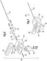
- FIGURES 1-9 illustrate various components and process steps for an exemplary cartridge shuttle subsystem 20.
- This shuttle subsystem "shuttles” or transfers hair grafts from the body surface and/or harvesting tool into the cartridge and back from the cartridge into an implanting tool.
- the subsystem 20 comprises a block-like base member 22 having a distal end 24 and a proximal end 26. A longitudinal direction will be defined extending from the distal end 24 to the proximal end 26, while the transverse direction extends perpendicular thereto in a horizontal plane.
- the base member 22 defines a transverse channel 28 that receives therein a rectilinear cartridge 30.
- the cartridge 30 slides transversely within the channel 28 either manually or automatically, for example, under the control of a robotic manipulator (not shown).
- a tool 32 extends distally from the distal end 24 of the base member 22.
- the illustrated exemplary tool 32 for convenience and simplicity schematically represents both an FU removal/harvesting tool and an implanting tool, which can be interchangeably coupled to the base member 22.
- the harvesting tool includes a coring distal end, and both a harvesting tool and an implanting tool typically define therein a lumen or throughbore.
- An elongated rod-like obturator 34 projects proximally from the proximal end 26 of the base member 22. The use of the obturator 34 will be described below.
- the cartridge shuttle subsystem 20 further preferably includes an inspection device 36.
- the inspection device 36 may be used in variety of ways.
- the inspection device 36 could be used for purposes of counting the number of FUs that are transferred; or in more advanced systems, it may also allow for assessment or classification of, for example, the size and/or character of harvested follicular units.
- the base member 22 defines a longitudinal channel extending entirely through the body substantially along the midline thereof.
- the channel receives the tool 32 such as in an interference fit or with mutual threading.
- a transparent inspection tube 40 defines a throughbore that provides a continuation of the longitudinal channel across a gap 42 in the base member 22.
- the inspection device 36 includes a pair of vertically-oriented fingers 43 that extend into the gap 42 and flank the inspection tube 40.
- the fingers 43 contain sensors, such as light detectors, or cameras, etc., for inspecting and/or registering the FUs that travel through or pause in the inspection tube 40.
- the inspection device 36 comprises an LED transmitter and receiver combination in the fingers 43.
- the LED light beam is interrupted, which is sensed by the receiver. This signals to the system that an FU has passed. If during one harvesting step no FU is sensed, the system processor records the absence of an FU in that particular receptacle of the cartridge, and the receptacle, for example, may then be skipped in a subsequent implant sequence using that cartridge.
- Another exemplary means of inspecting FUs is an imaging system that acquires an image of any one follicular unit and utilizes image processing to assess, for example, the type, size of the FU and/or number of follicles therewithin, as well as to count them.
- Various ways to inspect and classify FUs are disclosed in two PCT applications directed to systems and methods for classifying and counting FUs, PCT/US07/76726 and published as WO 2008/024954 and WO 2008/024955, both filed on August 24, 2007 .
- the storage device or cartridge of the present invention could be used in conjunction with the systems described in these two PCT applications to provide information about the type of hair follicle unit located in selected receptacles in the cartridge 30.
- Various means of classifying could be used depending on the biological unit. For example, hair could be classified based on whether it is a multiple or single hair unit, while for other biological units the scheme could be their size, shape, chemistry, etc.
- the system of the present invention includes a processor for receiving signals from the inspection device 36 and the mechanism for transferring a biological unit into a known cartridge receptacle.
- the processor classifies the biological unit and records the classification for later recollection and selective retrieval from the corresponding cartridge receptacle.
- the inspection device 36 may include an image acquisition device, and the processor is an image processor configured for processing an image obtained by the image acquisition device.
- the image processor may be configured for counting and/or classifying the FU, including for example, calculating a contour of the segmented image of the FU, calculating an outline profile of the segmented image which disregards concavities in the calculated contour of the segmented image of the FU, determining the number of defects in the outline profile, and finally classifying the FU at least partially based on the number of determined defects.
- the image processor may be configured for recording or registering the FU.
- the image acquisition device may be one or more cameras, such as any commercially available cameras.
- the image acquisition device could be a video recording device (such as a camcorder). While it is preferred that the image acquisition device be a digital device, it is not necessary. It could be, for example, an analog TV camera that acquires an initial image which is then digitized into a digital image.
- the image processor may comprise any device programmed and configured to perform the method of registering, counting, and/or classifying a biological unit (e.g., an FU).
- a suitable image processor is any type of personal computer ("PC").
- the image processor may comprise an Application Specific Integrated Circuit (ASIC) or Field Programmable Gate Array (FPGA).
- ASIC Application Specific Integrated Circuit
- FPGA Field Programmable Gate Array
- the image processor may be programmed with software configured to perform the methods of the present invention.
- the present invention also provides components for tracking or monitoring the position of the FU as it "shuttles" or transfers from the body surface and/or harvesting tool into, for example, a storage cartridge, such as through the exemplary shuttle subsystem 20.
- FUs may be imaged and inspected as they pass through the inspection device prior to their implantation without any use of a storage cartridge.
- the inspected biological units, such as FUs may be classified and then immediately implanted into a desired location based on the results of the inspection and/or classification.
- Various embodiments, including those with or without the use of a storage cartridge may be employed using similar techniques, as described below.
- an inspection device assesses each FU (or a sampling of FUs) as it moves through the shuttle subsystem 20.
- a mechanism is used to transfer the FUs (or more generally biological units) past the inspection device and, for example, into one of the plurality of cartridge receptacles in those embodiments where the cartridge is used.
- the mechanism for transferring the FUs may be the open channel with a pressure differential, as described above, or another such mover like a conveyor, pick and place, or similar expedient.
- a strobe light may be fired at a point and time where a camera can obtain a clear image.
- an imaging device e.g. camera
- a tracking system located adjacent the channel through the shuttle subsystem 20 upstream of an imaging point may be used to detect the FU's presence in the shuttling system and measure its velocity.
- the tracking system in conjunction with a processor/controller may use the velocity information to strobe a lamp at the instant the FU is within the field of view of the imaging device.
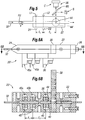
- FIGURE 5 schematically shows components for tracking/registering the movement of a biological unit such as an FU in the systems of the present invention.
- these components may be incorporated into the subsystem 20, and therefore like elements will be given like numbers.
- FIGURES 6A and 6B are side elevational and sectional view through a modified cartridge shuttle subsystem 20' with the addition of FU tracking components. This technique for monitoring, registering, inspection, and assessment of an FU of interest may also be useful in a handheld device for harvesting FUs, and illustration in the automated subsystem 20' should not be considered limiting.
- an FU is shown traveling at a velocity ⁇ through the lumen of a harvesting tool 32 that projects distally from the distal end of the base member 22.
- the lumen of the tool 32 leads into a longitudinal channel extending through the base member 22 and past an imaging point 44 aligned with an inspection device 36.
- the inspection device 36 in the illustrated example includes a camera C, a strobe S, and a beam splitter BS.
- the strobe S is shown aligned with the camera axis, although it may also be misaligned.
- the FU Prior to reaching the imaging point 44, the FU passes between a first or upstream checkpoint comprising a first light source L 1 and a first light detector D 1 , and a second or downstream checkpoint including a second light source L 2 and a second light detector D 2 .
- the first and second checkpoints register passage of the FU when it breaks the continuity of light transmission between the respective source and detector.
- a processor/controller receives inputs from these sensors and sends outputs to each of the various instruments, and includes a memory.
- the processor/controller may be adapted to receive signals from the inspection device, and performing one or more of the additional operations, including but not limited to registering passage of the biological unit through the inspection device and into one of the plurality of cartridge receptacles in those embodiments including the cartridge, counting biological units, and classifying biological units. Further, the processor/controller may record the results of one or more of the operations of registering, counting and classifying for later recollection and selective retrieval from the corresponding cartridge receptacle.
- an inspection device may be coupled to a manual or partially automated hand-held biological unit removal tool for real-time assessment of each biological unit.
- a follicular unit removal tool may incorporate an inspection device that displays to the user the type of FU (e.g., F1, F2, etc.). The user can then easily determine the subsequent action, such as by implanting the FU in the appropriate location, or expelling the FU into a container holding those types of follicular units.
- such a tool and inspection device could be coupled to the processor/controller which keeps track of the number of different types of FUs that have been removed.
- the various systems described herein are extremely useful for automated or robotic biological or follicular unit removal/management/implantation, they are also useful and desirable in conjunction with hand-held or other manual non-robotic tools.
- the distance between the first checkpoint and the second checkpoint is indicated as l 1
- the distance between the second checkpoint and the imaging point 44 is indicated as l 2 .
- the controller then triggers the strobe S at a time ⁇ t 2 after the FU passes the second or downstream checkpoint, and instructs the camera C to take a picture of the imaging point 44.
- the FU will be centered at the imaging point 44, or at least within the camera's field of vision 44', at the time the strobe S fires and the camera C takes a picture. This system thus ensures that a clear image of each FU can be obtained.
- Information from the images of the FUs can then be used for multiple purposes, including without limitation: registering passage of each FU through the shuttle system, counting the number of FUs, including those sent to the cartridge, classifying and sorting FUs, such as based on its size, character, the number of hairs therein (e.g., "F1" for a single hair follicular unit, "F2" for a two hair follicular unit, and so on), or keeping track and recording information on the type of an FU contained in each receptacle of the cartridge.
- the time deltas between the checkpoints and the imaging point 44 also remain fairly constant, which further ensures success of the image collection by eliminating transients. Moreover, an operator may sample the images and adjust the timing slightly if the FUs are not precisely centered at the imaging point 44.
- FIGURES 6A and 6B illustrate a modified shuttle subsystem 20' with the addition of FU tracking components.
- the subsystem 20' comprises a block-like base member 22 having a distal end 24 and a proximal end 26.
- a longitudinal direction extends from the distal end 24 to the proximal end 26, while the transverse direction extends perpendicular thereto in a horizontal plane.
- a transverse channel in the base member 22 receives a rectilinear cartridge 30 that slides either manually or automatically, for example, under the control of a robotic manipulator (not shown).
- An exemplary removal/harvesting tool 32 extends distally from the distal end 24 of the base member 22.
- FIGURE 6B shows the subsystem 20' in horizontal cross-section, and as in FIGURE 4 shows a gap 42 in the base member 22 within which is positioned the inspection device 36.
- the inspection device 36 schematically represents the assembly of the camera C, a strobe S, and a beam splitter BS as described above with respect to FIGURE 5 .
- the base member 22 also receives first and second checkpoints 45a, 45b within corresponding spaces 46.
- the checkpoints 45a, 45b each desirably include a light source and light detector positioned to sense longitudinal passage of a FU through the subsystem 20'.
- the upstream and downstream checkpoints 45a, 45b are spaced apart a distance l 1
- the downstream checkpoint 45b is spaced from the imaging point 44 a distance l 2 .
- the cartridge 30 includes a plurality of receptacles for receiving FUs. As each FU is inspected and identified by the device 36, the controller can manipulate the cartridge 32 to place particular FUs within particular receptacles, or simply catalog the contents of the receptacles of the cartridge. For example, all of the F1 FUs may be placed in one select group of receptacles, while the F2 and larger FUs will be placed in the rest of the receptacles.
- the longitudinal channel through the middle of the base member 22 continues across the transverse channel 28 (as seen in Fig. 2 ) through one of a number of receptacles formed in the cartridge 30.
- a tubular sleeve 47 defines a throughbore that forms a distal section of the longitudinal channel.
- the tubular sleeve 47 fits within a bore formed in the base member 22 and is secured therein with a cover 48 that is bolted to the base member.
- the obturator 34 is shown closely fit within the throughbore of the tubular sleeve 47.
- a plurality of O-rings or seals 49 shown in FIGURE 4 prevent fluid leakage from the various sections of the channel and the exterior.
- the base member 22 defines a plurality of transverse fluid ports that intersect the longitudinal channel. Specifically, a pair of proximal ports 50a, 50b extend from opposite sides of the base member 22 and converge in the middle, registering with a pair of side ports 51 (see FIGURE 2 ) in the tubular sleeve 47. A pair of distal ports 52a, 52b extend from opposite sides of the base member 22 and converge in the middle in fluid communication with a small section of the longitudinal channel between the tool 32 and the inspection tube 40.
- the ports 50, 52 receive connectors (not shown) of sources of fluid or vacuum. Therefore, as will be explained below in the description of use of the subsystem 20, differential pressures may be created along the longitudinal channel.
- the fluid used to pressurize the subsystem 20 is saline, although air may also be used.
- saline is preferred to help maintain hydration of the FUs during the harvesting and/or implant procedure.
- any other preservation solutions are equally useful in the present invention.
- Use of a preservation solution is advantageous as each receptacle desirably contains some of the preservation solution after being filled with an FU.
- the preservation solution may be cooled or chilled as desired.
- a storage device or cartridge 30 is provided.
- Such cartridge preferably has a high density of holes or receptacles to store FUs (or other appropriate biological objects) in small spaces.
- FUs or other appropriate biological objects
- Such cartridge preferably permits storage of FUs under a controlled environment, for example, keeping them sterile, or moist, or at a desired cool temperature.
- the shape or configuration of the storage device or cartridge 30 may take many forms, and neither the rectilinear or later-described cylindrical or disk-like shapes are necessary or limiting, and can vary according to the intended application.
- the storage devices of the present invention are advantageously configured to define a plurality of receptacles for receiving the biological units.
- Such storage devices can be manipulated to register each receptacle, for example, sequentially with harvesting and/or implanting tools.
- the storage devices are small enough to be easily exchanged within the overall subsystem or system, and easily sterilized if they are to be reused.
- the storage devices may have certain features which prevent reuse, and thus they are disposable.
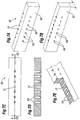
- FIGURES 7A-7E illustrate a number of views of one exemplary rectilinear cartridge 30 for use with the subsystem 20.
- FIGURE 7A shows a distal face (or first face) 60 while FIGURE 7B shows a proximal face (or second face) 62.
- the faces 60, 62 are planar and rectilinear, and lie in parallel. Some non-limiting examples of the rectilinear cartridges are those shaped like squares or rectangles.
- a thickness dimension t shown in FIGURE 7B extends perpendicular to the faces 60, 62.
- a plurality of receptacles 64 extend entirely through the cartridge 30 from the distal face 60 to the proximal face 62.
- Each of the receptacles 64 defines a first opening 66 at the distal/first face 60, and a pair of second openings 68 at the proximal/second face 62.
- the precise exemplary shape of the receptacles 64 of this embodiment is seen in cross-section in FIGURES 7D and 7E , and may be easily formed, for example, by drilling one large hole from the distal face 60, and two smaller holes from the proximal face 62.
- the cartridge 30 further defines a plurality of indexing notches 70 along an upper edge on the proximal side. The notches 70 can be used to displace the cartridge 30, or as location indicators for each of the receptacles 64.
- a central bore 72 having a constant diameter extends between the faces 60, 62. As will be described below, the bore 72 permits passage of the obturator 34 through the cartridge 30.
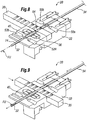
- FIGURES 8 and 9 illustrate two stages in a process for first harvesting and then implanting an FU.
- the FU is shown in FIGURE 8 in proximity to the tool 32.
- the tool 32 is designed for removing the FU from a body surface, and may include a sharp distal tip or any other structure for grasping and removing the FU.
- the operator or an automated system manipulates the shuttle subsystem 20 so that the FU enters a lumen 74 of the tool 32. For example, the operator may cause the tool 32 to plunge into a body surface around the FU.
- the tool 32 is retracted from the body surface and a pressure differential applied through the lumen 74 to cause the FU to translate in a proximal direction toward the receptacle 64.
- the pressure differential along the longitudinal channel is controlled by the relative pressures of fluid at the ports 50, 52.
- the inspection device 36 registers, counts, and/or classifies it. Desirably the FU continues at a constant rate through the longitudinal channel into the receptacle 64. Alternatively, the FU may be caused to pause in or slow down through the inspection tube 40 so that the inspection device 36 obtains a sufficient image for classification purposes.
- the FU monitoring components seen in FIGURES 5 and 6A-6B may be used to monitor the position of the FUs passing through the longitudinal channel, and in particular when each FU passes the inspection device 36 that includes an imaging device, such as a camera.
- An image of each FU may be analyzed in real-time to determine, for example, the character, count, size, and other characteristics of the FU, which is then further processed accordingly, such as by aligning the cartridge 30 along the transverse channel 28 to position a selected receptacle to receive the FU.
- the end of travel of the FU is at the proximal end of the first receptacle 64.
- fluid passes therethrough but the FU does not.
- the speed of the FU as it approaches the receptacles 64 may be reduced by providing parallel flow channels (not shown), or through various structural means, some of which are described in reference to another embodiment below.
- the FU has been stored in the receptacle 64.
- the system or operator then indexes the cartridge 30 along the transverse channel 28 to position one of the other receptacles into registration with the longitudinal channel, and the process of harvesting an FU is repeated.
- the cartridge 30 may be removed until it is ready for use in implanting the FUs back into a body surface of a recipient. Indeed, a plurality of cartridges 30 may be filled before the implant procedure. Or, the FUs stored in each cartridge may be immediately implanted without changing the cartridge.
- the linear pattern of receptacles 64 in the cartridge 30 is exemplary only, and any number of receptacle patterns may be utilized.
- the cartridge will have to be displaced in at least two directions to register each receptacle with the longitudinal channel through the subsystem 20.
- a close-packed matrix that does not consist of regularly spaced perpendicular rows may be used.
- a cartridge 30 that has receptacles filled with FUs is positioned within the base member 22 and one of the receptacles 64 registers with the longitudinal channel.
- Shuttling of the hair follicles from the cartridge to the implant tool could be accomplished using various approaches.
- a pressure differential in the distal direction may urge the FU out of that receptacle and into either the inspection tube 40 or implant tool 32.
- the vacuum tube 136 described above that creates a pressure differential urging the FU in the proximal direction can also be used to reverse the pressure differential to proper the FU distally.
- the implant tool 32 may be the same as the harvesting tool previously used, but is typically configured differently, thus requiring a change out.
- the FU may be pushed from the cartridge into the implant tool using, for example, a mechanical device such as obturator, as shown in FIGURE 9.
- FIGURE 9 illustrates the cartridge 30 having been transversely displaced to register the bore 72 with the longitudinal channel.
- the operator or system causes the distal end of the implanting tool 32 to enter the body surface of the recipient.
- the distal end of the implanting tool 32 may be sharpened, or the tool may be introduced into a previously formed puncture or incision.
- the operator or system then translates the obturator 34 entirely through the longitudinal channel, thus pushing the FU out of the tool 32.
- a combination of mechanical pushing and pressure differential could be used to expel FU from the cartridge.
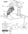
- FIGURE 10 is a schematic perspective view of an exemplary robotic biological unit harvesting and implant system 100 according to another aspect of the present invention.
- the system 100 includes a robotic arm 102 having a head assembly 104 mounted for rotation on a down tube 106 of the robotic arm.
- Various arrows are shown to illustrate the movement capabilities of the system 100.
- motors and other such movement devices incorporated in the head assembly 104 enable fine movements of an operating tip 108 in multiple directions.
- the operating tip 108 is shown positioned over a body surface 110, in this case a strip of tissue having hair follicles thereon.
- a personal computer 112 acting, for example, through a robotic control 114 controls the various movement devices of the robotic arm 102 and head assembly 104.
- the control system or mechanism 114 may be operatively coupled to the robotic arm and configured to control the motion of the robotic arm, including the motion based on the images or data acquired by any image acquisition device that could be used with the system.
- all processing and controls of all movements of all the tools including harvesting and implanting tools, the robotic arm and any other moveable parts of the assembly, and those based on the images or data acquired by the image acquisition device, may be incorporated in one processing and control system, such as 114.
- An operator monitors conditions and provides instructions through a monitor 115, keyboard 116, and mouse 118. A magnified image of the body surface 110 can be seen on the monitor 115.
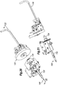
- FIGURES 11-13 are perspective and elevational views of the head assembly 104 of the system 100.
- the side view of FIGURE 12 shows the body surface 110 in proximity to the operating tip 108.
- a bank of LEDs 120 illuminates the body surface 110 so that an imaging device, which is a pair of cameras 122 in the illustrated embodiment, obtains a clear picture for transmission back to the monitor 115.
- Various components are mounted for rotation or linear translation relative to the down tube 106 of the robotic arm 102. Stepper motors, hydraulic cylinders, and the like may be used, and will not be described in great detail herein.
- FIGURES 11-13 illustrate a cylindrical cartridge 130 mounted in the head assembly 104 of the illustrated embodiment for indexed rotation on an axis that is parallel to the axis of a shaft 132 leading to the operating tip 108.
- the shaft 132 mounts on the head assembly in a manner that permits linear translation along its axis.
- a proximal end 134 of the shaft 132 projects toward a distal side of the cartridge 130.
- a vacuum tube 136 mounts to the head assembly 104 in a manner that permits linear translation of a distal tip thereof.
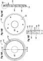
- FIGURES 14A-14D are various views of an exemplary disk-shaped cartridge 130 according to another aspect of the present invention.
- the cartridge 130 comprises a body 140 defining a plurality of receptacles 142 therein.
- the body 140 defines an outer cylindrical surface 144, a flat circular distal face (or first face) 146, and a flat circular proximal face (or second face) 148.
- the axial distance between the faces 146, 148 defines a thickness t dimension, as seen in FIGURE 14D .
- the receptacles 140 extend axially through the body 140 from a first opening 150 at the distal face 146 to a second opening 152 at the proximal face 148.
- Each of the receptacles 142 is analogous to the receptacles 64 for the previously described cartridge shuttle subsystem 20 of FIGURES 1-9 .
- FIGURE 14A shows the distal side of the cartridge 130 illustrating the distal/first face 146 and the plurality of first openings 150 for the corresponding receptacles 142.
- the receptacles 142 are arrayed in a circular pattern about the axis of the cartridge 130.
- the circular pattern of receptacles 142 is located close to the periphery of the cartridge (along the circumference), which maximizes the number of receptacles because of a minimum required spacing therebetween. It should be understood that multiple circular or non-circular patterns of receptacles may be provided through the cartridge.
- the circular pattern of receptacles 142 aligns with the axis of the shaft 132 seen in FIGURE 13 . Indexing or rotating the cartridge 130, therefore, causes select ones of the receptacles 142 to register with the proximal end 134 of the shaft 132.
- the receptacles 142 could be arranged in numerous ways with a corresponding change in the required movement of the cartridge 130 relative to the shaft 132 (or visa versa).
- the receptacles 142 could be arranged in a pattern of at least one circular array of receptacles along a circumference of the storage device as shown, or the pattern may include a second (or third, etc.) circular array of receptacles concentrically arranged at a smaller radius than the first one.
- the pattern could be random, or in certain order, have aligned rows or circles, or other arrangements. The pattern is limited only by the potential movement of the cartridge 130 relative to the shaft 132 (or visa versa).
- the cartridge 130 further includes a cover 160 on its proximal/second side that extends over the second openings 152 of the receptacles 142.
- the cover 160 is made of a permissive medium as described below to permit access via a number of means into the receptacle.
- transmissive medium refers to any number of materials that could be used with a storage cartridge according to one aspect of the present invention to facilitate movement of a biological unit to or from the cartridge receptacles.
- examples of such mediums include meshes, screens, paper, elastomeric materials such as silicone, various contiguous polymers, various resealable materials that allow creation of a slit or puncture that closes or reseals on its own, etc. Any of the above-listed exemplary materials may cover the back (or proximal) side of the cartridge to prevent FUs from passing through and exiting the cartridge, while at the same time allowing air and/or liquids to pass through.
- the permissive mediums useful in the present invention are used to cover an opening of a receptacle of a cartridge for storing, for example, follicular units (FUs), and must possess sufficient structural integrity to block passage of an FU that is propelled into the receptacle with some velocity.
- the permissive medium is preferably either porous to permit air or fluid to pass freely therethrough (air/fluid permeable), or is susceptible to puncture with a tool.
- permissive medium is an air and/or fluid permeable medium. If the cover 160 is permeable by air or fluids then a pressure differential through the receptacles can be established across the cover material. For instance, a mesh that permits passage of saline is a permeable medium, and therefore a permissive medium.
- a "puncturable medium” refers to any number of materials that can relatively easily be punctured or pierced to create an opening, at least temporarily. Note that a "puncturable medium" may be air and/or fluid permeable, as in a mesh, or not.
- cover 160 is fluid impermeable yet puncturable, then for example a pressure differential through the receptacles can be established using a probe that extends into the receptacle through the cover.
- metal may be a puncturable medium if it is very thin, as in a foil, or arranged in a fine mesh or screen.
- the puncture is accomplished using an obturator (or rod, or needle, typically metallic) so that an opening can be formed to allow for air/fluid passage.
- the opening may be either permanently formed or temporarily formed in case of resealable medium.
- openings may be formed to permit introduction of saline or other known preserving solution to the receptacles.
- puncturable mediums include meshes/screens (e.g., of polymer), medical filter materials that are air-permeable but not fluid permeable, and silicone rubbers.
- the puncturable medium is non-fraying, meaning that the puncture does not result in particles being shed or severed therefrom. Such particles could degrade or contaminate the biological unit in the receptacle.
- An exemplary permissive medium may be medical grade silicone rubber poly-dimethylsiloxane (PDMS) which can be punctured by an obturator sized to fit through the receptacles 142.
- PDMS medical grade silicone rubber poly-dimethylsiloxane
- the cover 160 may be attached to the body 140 of the cartridge 130 by virtue of a retaining ring 162.
- the retaining ring 162 may be fastened to the body 140 with screws or bolts, or glue may be used for a more permanent attachment.
- the use of the retaining ring is not necessary, and cover 160 could be directly attached (either permanently or removably) to the body of the cartridge, for example by gluing, fusing, clipping, etc. Two different ways for clamping the cover 160 to the body 140 are shown below with respect to FIGURES 17 and 19 .
- an amount of saline or other known preserving solution is placed in each receptacle 142 of the cartridge 130 so that hair follicles or other biological objects remain hydrated or maintain a cool temperature during the storage.
- One way to accomplish this is to utilize a permissive medium for the cover 160 that wicks the preservative fluid against the second openings 152 and therefore transfers it to each receptacle due to surface tension effects (i.e., capillary action).
- Another way is to directly insert a drop of fluid into each receptacle 142.
- the cartridge 130 (or 30 in the earlier embodiment) is not limited to use with the robotic system of FIGURE 10 , but also has utility in other procedures.
- various kinds of biological units may be managed using the cartridge of the present invention.
- One example is a process where a plurality of biopsy samples are taken and stored for later analysis.
- the system desirably matches the donor location with the receptacles, and then can deliver any one biopsy sample as needed with knowledge of the area of the body from which it came.
- the cartridge may be utilized in a primarily manual system, without the aid of the robotic system described herein.
- the cartridge of the present invention may be utilized in a manual or primarily manual system where harvesting and/or implanting is accomplished by a person (such as, physician or trained technician) using, for example, a hand-held device, even though such device or a procedure may be automated to various degrees.
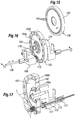
- FIGURE 15 is a perspective view of the disk-shaped cartridge 130 prior to loading into a harvesting/implanting system 100.
- the proximal side of the cartridge is illustrated and it should be noted that the cover 160 is not shown so as to expose the receptacles 142.
- FIGURE 16 is a perspective view of a cartridge 130 mounted in proximity to certain of the harvesting/implanting system 100 components with which it directly interacts.
- the cartridge 130 is oriented the same way as in FIGURE 15 , with the proximal side to the left, though in this operational view the permissive medium cover 160 occludes the receptacles 142.
- FIGURE 16 also illustrates an alternative configuration for mounting the cover 160.
- inner and outer mounting rings 164a, 164b bolt to the body of the cartridge 130 and hold the retaining rings 166a, 166b within grooves (not numbered) in the proximal face of the cartridge 130.
- the retaining rings 166a, 166b capture and frictionally hold inner and outer circular edges of the cover 160, which is made of the material that flexes or can be pressed into the grooves.
- the cover 160 may be made of a silicone (PDMS) elastomer in the shape of the annulus with the inner and outer edges thereof retained in the grooves by the rings 164, 166.
- PDMS silicone
- FIGURE 16 shows the vacuum tube 136 passing through a frame member 168 mounted on the head assembly 104 ( FIGURE 13 ).
- a spring member 170 is seen at the terminal end of the vacuum tube 136, which helps ensure good suction contact between the tube and the proximal face of the cartridge 130 and reduces the need for precise relative positioning tolerances.
- the head assembly 104 includes a movement mechanism (not shown) for translating the vacuum tube 136 toward and away from the cartridge 130, as indicated by the double-headed arrow.
- the frame member 168 may also provide a platform for mounting a piercing device 172 adjacent the terminal end of the vacuum tube 136.
- the piercing device 172 comprises a thin rod, desirably pointed or sharpened, which lies at the same radial distance from the rotational axis of the cartridge 130 as the vacuum tube 136. In other words, the piercing device 172 aligns with the circular pattern of receptacles 142.
- the piercing device 172 may be utilized to pre-puncture holes or slits through the cover 160 for each of the receptacles.
- the piercing device 172 may be utilized if the terminal end of the vacuum tube 136 comprises a thin probe for entering the receptacles, and the probe is insufficiently sharp to cleanly form its own hole. Such an embodiment will be described below in reference to FIGURE 19 .
- the terminal end of the vacuum tube 136 may be pointed to perform the puncture rather than using a separate piercing instrument.
- FIGURE 16 also illustrates a housing 174 within which may be located a rotational prime mover, such as a stepper motor, for rotating or indexing the cartridge 130.
- a rotational prime mover such as a stepper motor
- Precise rotational movement of the cartridge 130 registers each of the receptacles 142 in turn relative to the vacuum tube 136.
- Software controlling the movement mechanism enables any one of the receptacles 142 to be registered as desired.
- an inspection system for assessing the characteristic of each FU may be incorporated into the harvesting procedure, and an understanding of what type of FU is in each receptacle 142 enables the system to implant smaller FUs in one location, while larger FUs are implanted in another location.
- FIGURE 17 is an enlarged sectional view of the distal components of FIGURE 16 , and illustrates exemplary pressure differential reduction structure desirably provided to slow down the velocity of a biological unit traveling toward the cartridge 130.
- a source of suction is applied to a proximal side of a selected receptacle 142 during the harvesting process, which creates a pressure differential in the proximal direction thus urging an FU into the receptacle.
- the magnitude of the pressure differential typically remains constant during travel of the FU along the path from the harvesting tool to the receptacle 142, because the suction required to pull the FU from the body surface is relatively high, which results in the FU moving a high rate of speed toward the receptacle.
- This high velocity movement potentially may cause damage to the FU when it halts at the proximal end of the cartridge receptacle, such as when it impacts the cover 160. Because of the short travel duration, however, it would be difficult though not impossible to provide a system which steps down the magnitude of the suction halfway between the harvesting tool and the receptacle.
- structure may be provided along a path in which the biological unit travels from the removal tool to the storage device receptacle to reduce the pressure differential along a portion thereof and thereby reduce the speed of the FU along the path.
- the structure may comprise a parallel flow path outside of the main path which terminates just before the path reaches the cartridge.
- the FU travel path from the operating tip 108 through the distal shaft 132 passes along a main tube 173 surrounded by an outer tube 175.
- An annular space is created between the tubes 173, 175.
- Two sets of bypass holes 177 spaced apart substantially the length of the shaft 132 enable flow to enter the annular space. This reduces the pressure within the main tube 173 and therefore slows down travel of the FU in that area.
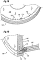
- FIGURE 18 an exemplary pressure relief structure for the cartridge receptacles 142 is shown.
- a source of suction is applied to a proximal side of a selected receptacle 142 during the harvesting process, the pressure differential continues for short period after the FU reaches the receptacle. During that time, it is desirable to mitigate the dehydrating effects of the suction on the FU, for instance if the FU completely includes the receptacle on its proximal side.
- one of the receptacles 142 shown is provided with pressure relief channels 174 to limit the maximum suction created within the receptacle to less than a magnitude of the source of suction.
- the vacuum tube 136 comprises a source of suction which, if sealed around the proximal end of the receptacle 142, would apply a magnitude of suction to the receptacle. Without the pressure relief channels 174, the FU within the receptacle would be exposed to the maximum suction. By providing alternative paths for fluid or air into the vacuum tube 136, the maximum suction to which the FU is exposed is less than the magnitude of the source of suction.
- the pressure relief channels 174 are shown as small notches in a cross pattern at the second opening or proximal end of the receptacle 142. Of course, other configurations can be used, including only one notch. Additionally, the pressure relief channels 174 are only shown in one receptacle for example purposes, and desirably are provided for all the receptacles.
- FIGURE 19 illustrates an alternative method for applying a source of suction (creating a pressure differential) to the receptacles 142.
- a suction probe 176 extends from the distal end of the vacuum tube 136.
- the suction probe 176 features a blunt, closed end 177 and at least one side port 178 near the closed end.
- the outer diameter of the suction probe 176 is sufficiently smaller than the inner diameter of the receptacle 142 so as to provide a gap and permit air or fluid to flow around the probe and into the side port 178.
- the suction probe 176 extends through the permissive medium cover 160 into the receptacle 142.
- the cover 160 is optionally retained against the proximal face of the cartridge 130 by a plate 179 that is in turn secured by an outer ring 181.
- a circular array of tapered openings (not numbered) in the plate 179 register with each of the receptacles 142, which facilitates introduction of the probe 176 to the receptacle.
- Suction probe 176 may be used with any of the permissive mediums, but is especially useful with a cover 160 that is relatively impermissible to fluids. Pulling suction directly through such a material would be impractical, and therefore the probe 176 must be inserted through the cover 160 into the receptacle.
- the cover 160 is made of a material that self-seals after removal of the probe 176; for example, silicone (PDMS) elastomer.
- the probe 176 may be pushed directly through the cover 160, but given its blunt shape pre-formed slits or holes are desirably provided.
- the piercing tube 172 illustrated in FIGURE 16 may be used to form such holes.
- a particularly useful piercing tube 172 is shaped in the form of a Huber needle which is designed so as not to core a hole, but instead just form a slit which is self-sealing.
- the terminal end of the suction probe 176 may be more pointed, such as in the shape of a Huber needle, so as to form the hole itself, but consideration should be given to the effect on the FU when it contacts the sharpened probe.
- FIGURES 20 and 21 are perspective and side views isolating follicular unit shuttle components from the overall head assembly 104. These components can also be seen incorporated in head assembly 104 in FIGURES 11-13 . To describe important operational interactions of the system, or relative movement between the distal end of the system including operating tip 108, the cartridge 130, and the proximal end of the system including vacuum tube 136 will be described.
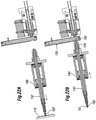
- FIGURES 22A-22D illustrate a sequence for harvesting an FU
- FIGURES 23A-23B describe a sequence for implanting an FU. It should be understood that these operations may be carried out sequentially by first filling the cartridge 130, and then emptying it without detaching from the system.
- a cartridge may hold 125-500 FUs, while a typical procedure requires up to 2000 FUs.
- the number of receptacles is of course variable and a single cartridge may hold all that would be needed.
- FIGURES 22A-22D are sectional views through the shuttle components taken along line 22-22 of FIGURE 20 , showing a sequence of operation for harvesting or removing a follicular unit from a body surface 110 and shuttling it to the cartridge 130.
- the shaft 132 is shown after having been displaced to the left within a cylinder 180. This action causes a harvesting/removal tool 182 to punch into the body surface 110 to a predetermined depth. The depth of penetration of the tool 182 is determined with knowledge of the distance between the tool and the body surface prior to displacement of the shaft 132.
- a follicular unit FU is shown positioned within a lumen of the removal tool 182. Also, the assembly of the shaft 132 and cylinder 180 is shown translated to the right so that the proximal end 134 contacts the cartridge 130. The throughbore of the shaft 132 registers with one of the receptacles 142 in the cartridge 130.
- FIGURE 22C illustrates a step wherein the FU shuttles from the removal tool 182 through the shaft 132 and into the cartridge receptacle 142. This may be accomplished using a pressure differential created, for example, by suction through the vacuum tube 136.
- This step of shuttling the FU in FIGURE 22C desirably utilizes the velocity reducing bypass structure described above with respect to FIGURE 17 , as well as the pressure reduction channels described with respect to FIGURE 18 .
- a mechanical shuttle may be utilized to transfer the FU into the receptacle 142.
- a rod or obturator (not shown) may be provided that extends through the shaft 132 and pushes the FU until it deposits into the receptacle 142.
- FIGURE 22D shows the assembly including the shaft 132 moving away from the cartridge 130 into distal direction, and the assembly including the vacuum tube 136 moving away from the cartridge 130.
- the cartridge 130 is free to rotate and index another receptacle into registration with the distal and proximal components of the shuttle subsystem.
- the shuttle subsystem components are shown essentially in the positions from FIGURE 22D , although instead of a harvesting/removal tool, the distal end of the shaft 132 features an implant tool 184.
- a receptacle 142 having an FU registers with the lumen of the shaft 132.
- the vacuum tube 136 On the proximal side, the vacuum tube 136 has been removed and replaced with a solid rod-like obturator 186.
- the obturator 186 translates linearly along its axis through the receptacle 142 and through the entire length of the shaft 132, and may be propelled in a number of ways including by contact with a plurality of wheels 188.
- FIGURE 23B shows the three components brought together and the obturator 186 passed though the receptacle 142 and entire shaft 132 until the FU reaches the implant tool 184.
- the implant tool 184 may be used to deposit the FU into a preformed incision or create a new incision in a body surface.
- shuttling of the hair follicles from the cartridge to the implant tool could be accomplished using several alternative approaches.
- One example is to push the FUs from the cartridge all the way through the distal end of the implant tool using the obturator as described.
- Another option is to use a pressure differential to urge the FU out of each receptacle and into the implant tool.
- the vacuum tube 136 described above that creates a pressure differential urging the FU in the proximal direction can also be used to reverse the pressure differential to propel the FU distally.
- a combination of physical pushing and pressure could be used.
Landscapes
- Health & Medical Sciences (AREA)
- Life Sciences & Earth Sciences (AREA)
- Surgery (AREA)
- Engineering & Computer Science (AREA)
- Animal Behavior & Ethology (AREA)
- General Health & Medical Sciences (AREA)
- Biomedical Technology (AREA)
- Heart & Thoracic Surgery (AREA)
- Veterinary Medicine (AREA)
- Public Health (AREA)
- Molecular Biology (AREA)
- Nuclear Medicine, Radiotherapy & Molecular Imaging (AREA)
- Medical Informatics (AREA)
- Robotics (AREA)
- Transplantation (AREA)
- Pathology (AREA)
- Dermatology (AREA)
- Cardiology (AREA)
- Oral & Maxillofacial Surgery (AREA)
- Vascular Medicine (AREA)
- Surgical Instruments (AREA)
- Prostheses (AREA)
Priority Applications (1)
| Application Number | Priority Date | Filing Date | Title |
|---|---|---|---|
| EP16200790.0A EP3155976B1 (en) | 2007-09-29 | 2008-08-21 | Systems for harvesting, storing, and implanting hair grafts |
Applications Claiming Priority (3)
| Application Number | Priority Date | Filing Date | Title |
|---|---|---|---|
| US99718807P | 2007-09-29 | 2007-09-29 | |
| US12/194,370 US8211134B2 (en) | 2007-09-29 | 2008-08-19 | Systems and methods for harvesting, storing, and implanting hair grafts |
| PCT/US2008/010034 WO2009045255A1 (en) | 2007-09-29 | 2008-08-21 | Systems and methods for harvesting, storing, and implanting hair grafts |
Related Child Applications (2)
| Application Number | Title | Priority Date | Filing Date |
|---|---|---|---|
| EP16200790.0A Division EP3155976B1 (en) | 2007-09-29 | 2008-08-21 | Systems for harvesting, storing, and implanting hair grafts |
| EP16200790.0A Division-Into EP3155976B1 (en) | 2007-09-29 | 2008-08-21 | Systems for harvesting, storing, and implanting hair grafts |
Publications (2)
| Publication Number | Publication Date |
|---|---|
| EP2197357A1 EP2197357A1 (en) | 2010-06-23 |
| EP2197357B1 true EP2197357B1 (en) | 2017-03-08 |
Family
ID=40509205
Family Applications (2)
| Application Number | Title | Priority Date | Filing Date |
|---|---|---|---|
| EP08795551.4A Active EP2197357B1 (en) | 2007-09-29 | 2008-08-21 | Systems for harvesting, storing, and implanting hair grafts |
| EP16200790.0A Active EP3155976B1 (en) | 2007-09-29 | 2008-08-21 | Systems for harvesting, storing, and implanting hair grafts |
Family Applications After (1)
| Application Number | Title | Priority Date | Filing Date |
|---|---|---|---|
| EP16200790.0A Active EP3155976B1 (en) | 2007-09-29 | 2008-08-21 | Systems for harvesting, storing, and implanting hair grafts |
Country Status (10)
| Country | Link |
|---|---|
| US (5) | US8211134B2 (pt) |
| EP (2) | EP2197357B1 (pt) |
| JP (3) | JP5184641B2 (pt) |
| KR (1) | KR101155219B1 (pt) |
| CN (1) | CN101801279B (pt) |
| AU (1) | AU2008307698B2 (pt) |
| BR (1) | BRPI0817565A2 (pt) |
| CA (3) | CA2696201C (pt) |
| ES (1) | ES2721754T3 (pt) |
| WO (1) | WO2009045255A1 (pt) |
Families Citing this family (94)
| Publication number | Priority date | Publication date | Assignee | Title |
|---|---|---|---|---|
| KR100685944B1 (ko) | 2000-12-05 | 2007-02-23 | 엘지.필립스 엘시디 주식회사 | 광배향성 물질 및 이를 이용한 액정표시소자 |
| US8501396B2 (en) | 2001-11-05 | 2013-08-06 | Medgenics Medical Israel Ltd. | Dermal micro-organs, methods and apparatuses for producing and using the same |
| US7468242B2 (en) | 2001-11-05 | 2008-12-23 | Medgenics, Inc. | Dermal micro organs, methods and apparatuses for producing and using the same |
| CA2788000C (en) * | 2003-05-01 | 2016-03-15 | Medgenics Inc. | Apparatus for harvesting a dermal micro-organ |
| US8758683B2 (en) * | 2007-08-08 | 2014-06-24 | Syngenta Participations Ag | System for sampling and tracking plant material |
| US8152827B2 (en) * | 2008-01-11 | 2012-04-10 | Restoration Robotics, Inc. | Systems and methods for harvesting, storing, and implanting hair grafts |
| FR2948646A1 (fr) * | 2009-07-29 | 2011-02-04 | Pascal Boudjema | Dispositif de stockage d'unites biologiques |
| WO2011075676A2 (en) | 2009-12-18 | 2011-06-23 | Knowlton Edward W | A skin treatment and drug delivery device |
| US8437874B2 (en) * | 2010-02-26 | 2013-05-07 | Syngenta Participations Ag | Transfer station for plant material sampling and tracking system |
| US8298246B2 (en) * | 2010-04-01 | 2012-10-30 | Restoration Robotics, Inc. | Follicular unit removal tool with pivoting retention member |
| ES2541839T3 (es) * | 2010-09-30 | 2015-07-27 | Stryker Trauma Gmbh | Sistema para insertar una espiga en un tornillo |
| US10772658B2 (en) | 2010-12-17 | 2020-09-15 | Srgi Holdings, Llc | Pixel array medical systems, devices and methods |
| US10702684B2 (en) | 2010-12-17 | 2020-07-07 | Srgi Holdings, Llc | Systems, devices and methods for fractional resection, fractional skin grafting, fractional scar reduction and fractional tattoo removal |
| US10695546B2 (en) | 2010-12-17 | 2020-06-30 | Srgi Holdings, Llc | Systems, devices and methods for fractional resection, fractional skin grafting, fractional scar reduction and fractional tattoo removal |
| US20160317170A1 (en) | 2013-12-06 | 2016-11-03 | Edward KNOWLTON | Pixel array medical systems, devices and methods |
| US11000310B2 (en) | 2010-12-17 | 2021-05-11 | Srgi Holdings, Llc | Pixel array medical systems, devices and methods |
| US11278309B2 (en) | 2010-12-17 | 2022-03-22 | Srgi Holdings, Llc | Pixel array medical systems, devices and methods |
| US10736653B2 (en) | 2013-12-06 | 2020-08-11 | Srgi Holdings, Llc | Pixel array medical systems, devices and methods |
| US10368904B2 (en) | 2013-12-06 | 2019-08-06 | Srgi Holdings, Llc | Pixel array medical systems, devices and methods |
| US11103275B2 (en) | 2010-12-17 | 2021-08-31 | Srgi Holdings, Llc | Pixel array medical systems, devices and methods |
| US10967162B2 (en) | 2010-12-17 | 2021-04-06 | Srgi Holdings, Llc | Systems, devices and methods for fractional resection, fractional skin grafting, fractional scar reduction and fractional tattoo removal |
| US8951266B2 (en) | 2011-01-07 | 2015-02-10 | Restoration Robotics, Inc. | Methods and systems for modifying a parameter of an automated procedure |
| JP5775212B2 (ja) * | 2011-04-26 | 2015-09-09 | ヤング リー,ヒー | 毛髪移植素材 |
| EP2713951A4 (en) * | 2011-05-23 | 2015-04-22 | California Inst Of Techn | AKKOMODATIVE INTRAOCULAR LENS |
| BR112014001248B1 (pt) | 2011-07-21 | 2020-12-08 | The General Hospital Corporation | aparelho e método para afetar o tecido adiposo subcutâneo |
| EP2819598B1 (en) | 2012-02-29 | 2019-07-03 | Stryker European Holdings I, LLC | System for handling an augmentation implant |
| US10543127B2 (en) | 2013-02-20 | 2020-01-28 | Cytrellis Biosystems, Inc. | Methods and devices for skin tightening |
| PT106977B (pt) * | 2013-05-30 | 2021-03-25 | Saúde Viável , Lda. | Sistema automatizado e método para transplante capilar diferenciado |
| CN205586030U (zh) * | 2013-07-26 | 2016-09-21 | 海罗尼克株式会社 | 毛发收集器及具有其的植发装置 |
| KR101521553B1 (ko) * | 2013-07-26 | 2015-05-20 | 주식회사 하이로닉 | 모낭 채집기 및 이를 구비하는 모발 이식장치 |
| US10555754B2 (en) | 2013-08-09 | 2020-02-11 | Cytrellis Biosystems, Inc. | Methods and apparatuses for skin treatment using non-thermal tissue ablation |
| ES2827049T3 (es) | 2013-10-02 | 2021-05-19 | Srgi Holdings Llc | Dispositivos médicos de conjunto de píxeles |
| CA2926322C (en) | 2013-10-02 | 2022-10-18 | Srgi Holdings, Llc | Pixel array medical devices and methods |
| KR200470718Y1 (ko) | 2013-10-28 | 2014-01-07 | 공동현 | 모발 이식용 식모기 |
| US11937846B2 (en) | 2013-12-06 | 2024-03-26 | Srgi Holdings Llc | Pixel array medical systems, devices and methods |
| US11229452B2 (en) | 2013-12-06 | 2022-01-25 | Srgi Holdings, Llc | Pixel array medical systems, devices and methods |
| US10953143B2 (en) | 2013-12-19 | 2021-03-23 | Cytrellis Biosystems, Inc. | Methods and devices for manipulating subdermal fat |
| RU2743044C1 (ru) | 2014-02-20 | 2021-02-12 | Марк ОЛЕЙНИК | Роботизированная кухонная система |
| US10448968B2 (en) | 2014-02-26 | 2019-10-22 | Infuez, Llc | Follicle extraction system and related methods |
| EP2946740B1 (en) * | 2014-05-23 | 2017-11-15 | Olcay Yilmaz Damar | Device for follicular unit transplantation |
| KR101614209B1 (ko) * | 2014-07-07 | 2016-04-20 | 주식회사 하이로닉 | 모발 이식 장치 |
| KR20160010203A (ko) * | 2014-07-18 | 2016-01-27 | 한국전자통신연구원 | 모낭 로딩 장치 및 방법 |
| KR101722029B1 (ko) * | 2014-08-14 | 2017-03-31 | 한국전자통신연구원 | 자동 모낭 공급 기능을 갖는 모발 이식용 식모기 |
| US10518409B2 (en) | 2014-09-02 | 2019-12-31 | Mark Oleynik | Robotic manipulation methods and systems for executing a domain-specific application in an instrumented environment with electronic minimanipulation libraries |
| BR112017009805A2 (pt) | 2014-11-14 | 2017-12-26 | Cytrellis Biosystems Inc | dispositivos e métodos para ablação da pele |
| WO2016098126A2 (en) * | 2014-12-15 | 2016-06-23 | Veol Medical Technologies Pvt. Ltd. | Graft tray |
| KR101516320B1 (ko) | 2015-01-21 | 2015-05-06 | 주식회사 하이로닉 | 모낭 채집기 및 이를 구비하는 모발 이식장치 |
| KR101597617B1 (ko) * | 2015-01-21 | 2016-02-26 | 주식회사 하이로닉 | 모발 이식장치 |
| US9974565B2 (en) * | 2015-05-21 | 2018-05-22 | Restoration Robotics, Inc. | Instruments, systems and methods for improving hair transplantation |
| KR102425251B1 (ko) * | 2015-06-03 | 2022-07-26 | 주식회사 오성전자 | 자동 식모 장치 |
| DE102015111448B3 (de) * | 2015-07-15 | 2016-05-25 | Nordischer Maschinenbau Rud. Baader Gmbh + Co. Kg | Vorrichtung und Verfahren zum Entfernen von Fleischgräten aus einem Fischfilet |
| KR102527391B1 (ko) * | 2015-07-22 | 2023-05-03 | 한국전자통신연구원 | 자동식 모낭 이식 식모기 |
| KR102458560B1 (ko) * | 2015-07-22 | 2022-10-31 | 한국전자통신연구원 | 자동식 모낭 이식 식모기 |
| US12257711B2 (en) | 2015-08-18 | 2025-03-25 | Mbl Limited | Robotic kitchen systems and methods in an instrumented environment with electronic cooking libraries |
| US11980389B2 (en) | 2015-08-31 | 2024-05-14 | Srgi Holdings Llc | Handed spiral slotted scalpet array |
| US11751903B2 (en) | 2015-08-31 | 2023-09-12 | Srgi Holdings, Llc | Pixel array medical systems, devices and methods |
| US11490952B2 (en) | 2015-08-31 | 2022-11-08 | Srgi Holdings, Llc | Pixel array medical devices and methods |
| KR102271869B1 (ko) * | 2015-11-12 | 2021-07-05 | 한국전자통신연구원 | 식모용 바늘에 모낭 유닛을 로딩하는 장치 |
| US11564706B2 (en) | 2019-10-28 | 2023-01-31 | Srgi Holdings, Llc | Pixel array medical systems, devices and methods |
| KR20230117470A (ko) | 2016-03-29 | 2023-08-08 | 사이트렐리스 바이오시스템즈, 인크. | 미용 피부 리설페이싱용 디바이스 및 방법 |
| ITUA20163005A1 (it) * | 2016-04-29 | 2016-07-29 | Grpe Electronics System Di Gabriele Rinetti | Dispositivo per il trapianto di unità follicolari |
| CN106109013B (zh) * | 2016-07-25 | 2018-12-21 | 北京博士园科技发展有限公司 | 一种毛发移植装置 |
| WO2018057630A1 (en) | 2016-09-21 | 2018-03-29 | Cytrellis Biosystems, Inc. | Devices and methods for cosmetic skin resurfacing |
| CN106618647B (zh) * | 2016-10-25 | 2018-12-18 | 汕头大学 | 一种毛囊提取和种植一体化器械 |
| US20180193059A1 (en) * | 2017-01-10 | 2018-07-12 | Electronics And Telecommunications Research Institute | Automatic hair follicle transplant apparatus |
| CN107260129A (zh) * | 2017-06-23 | 2017-10-20 | 深圳微美薇健康美容科技有限公司 | 一种用于检测毛囊发育的装置 |
| KR101800365B1 (ko) * | 2017-08-09 | 2017-11-22 | 김태희 | 자동 모낭분리장치 |
| KR101891643B1 (ko) * | 2018-01-22 | 2018-08-27 | 오대금속 주식회사 | 다발형 모발 이식기 |
| KR20190090329A (ko) * | 2018-01-24 | 2019-08-01 | 오대금속 주식회사 | 방사형으로 배치된 복수개의 시침채널로 이루어진 모발 이식기 |
| US11065034B2 (en) * | 2018-02-28 | 2021-07-20 | Electronics And Telecommunications Research Institute | Modular automatic hair implanter |
| EP3773314B1 (en) | 2018-04-09 | 2024-02-21 | Lütfi Keçici | Direct automatic transfer device for hair transplantation |
| KR102777560B1 (ko) * | 2018-07-02 | 2025-03-10 | 주식회사 오대 | 방사형으로 배치된 복수개의 시침채널로 이루어진 모발 이식기 |
| CN109182082A (zh) * | 2018-08-29 | 2019-01-11 | 南京新生医疗科技有限公司 | 毛囊脂肪组织分离板 |
| CN109044424B (zh) * | 2018-08-31 | 2020-09-29 | 南京新生医疗科技有限公司 | 一种植发机器人 |
| KR102564841B1 (ko) * | 2018-11-19 | 2023-08-09 | 한국전자통신연구원 | 자동 모발이식 장치 |
| WO2021059279A1 (en) * | 2019-09-26 | 2021-04-01 | Spider Medical Ltd. | An automated system and a method for performing hair restoration |
| JP7316913B2 (ja) * | 2019-11-15 | 2023-07-28 | Juki株式会社 | 毛髪供給装置 |
| MX2022010344A (es) * | 2020-02-21 | 2022-09-19 | Massachusetts Gen Hospital | Sistemas y metodos para un sistema de trasplante capilar con agujas de extraccion e implantacion. |
| CN111920519B (zh) * | 2020-08-07 | 2021-06-08 | 北京纳通医学科技研究院有限公司 | 机械臂末端的手术器械装置和手术机器人 |
| CN111839616B (zh) * | 2020-08-18 | 2023-03-21 | 重庆大学 | 一种毛囊提取结构的控制系统 |
| CN112353491B (zh) * | 2020-10-29 | 2021-09-14 | 北京唯迈医疗设备有限公司 | 一种介入造影和治疗手术通用机器人 |
| CN112314594A (zh) * | 2020-11-25 | 2021-02-05 | 长沙市雨花区黑植美尔医疗美容门诊部有限公司 | 一种植发用毛囊优选装置及其使用方法 |
| KR102237442B1 (ko) * | 2020-12-23 | 2021-04-06 | 김두희 | 모낭 이식 장치 |
| EP4395667A1 (en) * | 2021-09-02 | 2024-07-10 | Andreani, Silvano | Handling device with increased functionality for hair transplantation operations |
| WO2023031636A1 (en) * | 2021-09-02 | 2023-03-09 | Tricos - Technology S.R.L. | Handling device with increased functionality for hair transplantation operations and surgical procedure |
| KR102658036B1 (ko) * | 2021-09-15 | 2024-04-18 | 주식회사 메타약품 | 자동제어가 가능한 식모기 자동구동시스템 |
| KR102495863B1 (ko) * | 2021-10-13 | 2023-02-07 | 주식회사 오대 | 멀티채널 식모기를 장착하는 장착 모듈 및 이를 구비한 자동 식모장치 |
| US20230346378A1 (en) * | 2022-05-02 | 2023-11-02 | Covidien Lp | Surgical robotic systems and reloading modules thereof |
| EP4615364A1 (en) * | 2022-11-09 | 2025-09-17 | The General Hospital Corporation | Systems and methods for uni-to-multi hair extraction-implantation |
| CN116831113B (zh) * | 2023-06-13 | 2025-05-02 | 北京碧莲盛不剃发植发医疗美容门诊部有限责任公司 | 用于不剃发植发的毛囊存放装置 |
| US12433739B2 (en) * | 2023-07-28 | 2025-10-07 | EnGraft Technologies, Inc. | Hair transplantation surgery with graft-on-demand processing of follicular units |
| WO2025090099A1 (en) | 2023-10-23 | 2025-05-01 | California Institute Of Technology | Liquid accommodating intraocular lens with an asymmetric chamber |
| US12616567B2 (en) | 2023-10-23 | 2026-05-05 | California Institute Of Technology | Liquid accommodating intraocular lens with suspended central lens |
| CN117796884B (zh) * | 2023-12-21 | 2024-10-25 | 上海磅盈策科技有限公司 | 针头驱动机构、毛囊种植针组件及毛囊提取及种植装置 |
Family Cites Families (53)
| Publication number | Priority date | Publication date | Assignee | Title |
|---|---|---|---|---|
| US2366886A (en) * | 1942-11-20 | 1945-01-09 | American Tag Company | Capsule handling apparatus |
| GB1525841A (en) * | 1976-05-18 | 1978-09-20 | Hundon Forge Ltd | Drug implanters |
| US4451254A (en) | 1982-03-15 | 1984-05-29 | Eli Lilly And Company | Implant system |
| US4485933A (en) * | 1983-11-04 | 1984-12-04 | Marpac Industries, Inc. | Closure for receptacles containing a pressurized gas |
| US5439475A (en) | 1990-07-03 | 1995-08-08 | Bennett; David M. | Tissue grafting method using an apparatus with multiple tissue receiving receptacles |
| FR2696334B1 (fr) | 1992-10-01 | 1994-12-02 | Boudjema J Pascal | Dispositif pour transplantation de greffons capillaires de petit diamètre. |
| AU688776B2 (en) * | 1993-06-23 | 1998-03-19 | Brown University Research Foundation | Method and apparatus for sealing implantable, membrane encapsulation devices |
| NO941494L (no) * | 1994-04-25 | 1995-10-26 | Olav L Aasberg | Apparat for innpoding av hårrötter, samt anordning for anbringelse av hårrötter på samleblånd til bruk i apparatet |
| US5611811A (en) | 1994-04-29 | 1997-03-18 | Star-Wood, Inc. | Micro and mini hair transplant device |
| US5417683A (en) | 1994-07-13 | 1995-05-23 | Shiao; I-Shen | Mini-graft hair implanting device for implanting multiple clumps of hair follicles at one time |
| US5643308A (en) | 1995-02-28 | 1997-07-01 | Markman; Barry Stephen | Method and apparatus for forming multiple cavities for placement of hair grafts |
| US6270511B1 (en) | 1995-02-28 | 2001-08-07 | Barry S. Markman | Hair transplant implanter and template system |
| US5792169A (en) | 1995-02-28 | 1998-08-11 | Markman; Barry Stephen | Method and apparatus for forming multiple cavities for placement of hair grafts |
| US5868758A (en) | 1995-02-28 | 1999-02-09 | Markman; Barry S. | Method apparatus and kit for performing hair grafts |
| US5951572A (en) | 1995-02-28 | 1999-09-14 | Markman; Barry S. | Method, apparatus and kit for performing hair grafts |
| US5584851A (en) | 1995-05-09 | 1996-12-17 | Banuchi; Isabel M. | Hair transplant instrument and method for transplanting hair grafts |
| US5782851A (en) | 1996-04-10 | 1998-07-21 | Rassman; William R. | Hair transplantation system |
| JPH10210A (ja) * | 1996-06-14 | 1998-01-06 | Iken Kogyo:Kk | 植毛用組織採取器具 |
| US5817120A (en) | 1997-02-10 | 1998-10-06 | Rassman; William R. | Hair implanting instrument |
| IT1292287B1 (it) | 1997-04-24 | 1999-01-29 | Roberto Luigi Costanzo | Strumento chirurgico per il trapianto di capelli autologhi. |
| US5895403A (en) | 1997-10-17 | 1999-04-20 | Collinsworth; Lonnie Rae | Surgical cutting tool |
| JP2002527631A (ja) | 1997-10-30 | 2002-08-27 | アール キング,クリストファー | 自動ヘアイソレーション、およびプロセスシステム |
| US20010055809A1 (en) * | 1998-01-30 | 2001-12-27 | Harpal S. Mangat | Extending tissue preservation |
| FR2776180B1 (fr) | 1998-03-17 | 2000-08-11 | Pascal Boudjema | Dispositif d'implantation de greffons capillaires de petit diametre |
| US6027512A (en) | 1998-05-28 | 2000-02-22 | Bridges; Ronzee M. | Hair follicle harvesting device |
| US6572625B1 (en) | 1998-09-13 | 2003-06-03 | William R. Rassman | Hair transplant harvesting device and method for its use |
| US6632182B1 (en) * | 1998-10-23 | 2003-10-14 | The Trustees Of Columbia University In The City Of New York | Multiple bit, multiple specimen endoscopic biopsy forceps |
| US6056736A (en) | 1998-10-29 | 2000-05-02 | Markman; Barry S. | Device and method for loading hair grafts into a cartridge |
| NO20001060L (no) | 2000-03-02 | 2001-09-03 | Per Gunnar Werner | Magasin for kortvarig lagring av hartransplantat |
| US20030040766A1 (en) | 2000-03-08 | 2003-02-27 | Werner Per Gunnar | Apparatus and control system and method for hair transplantation |
| US6585746B2 (en) | 2000-04-20 | 2003-07-01 | Philip L. Gildenberg | Hair transplantation method and apparatus |
| JP3620020B2 (ja) | 2000-12-13 | 2005-02-16 | 峻 平山 | 連続植毛機 |
| KR100426613B1 (ko) * | 2001-05-19 | 2004-04-08 | 한국과학기술연구원 | 마이크로 로봇 구동시스템 |
| US7025774B2 (en) | 2001-06-12 | 2006-04-11 | Pelikan Technologies, Inc. | Tissue penetration device |
| EP1446669A1 (en) * | 2001-10-26 | 2004-08-18 | Advion BioSciences, Inc. | Method and device for chemical analysis |
| US7261721B2 (en) | 2002-12-16 | 2007-08-28 | Feller Alan S | Method and apparatus for follicular extraction and transplantation |
| US7144406B2 (en) | 2003-03-26 | 2006-12-05 | New Hair Institute | Hair transplant device |
| US7156856B2 (en) | 2003-04-29 | 2007-01-02 | Feller Alan S | Method and apparatus for follicular extraction and transplantation |
| US7481820B1 (en) | 2003-05-23 | 2009-01-27 | Sharon Keene | Tissue graft support apparatus |
| US7066329B2 (en) | 2003-07-21 | 2006-06-27 | Riley Medical, Inc. | Medical instrument holding and presentation system |
| JP2007520267A (ja) * | 2004-01-05 | 2007-07-26 | ラスマン、ウィリアム・アール | ヘアグラフトを移植するための方法及び装置 |
| WO2005120325A2 (en) * | 2004-06-07 | 2005-12-22 | Given Imaging Ltd | Method, system and device for suction biopsy |
| US20060127881A1 (en) | 2004-10-25 | 2006-06-15 | Brigham And Women's Hospital | Automated segmentation, classification, and tracking of cell nuclei in time-lapse microscopy |
| ES2380208T3 (es) * | 2005-08-10 | 2012-05-09 | C.R.Bard, Inc. | Sistema de transporte para inserción única, dispositivos de biopsia para muestra múltiple |
| US20070078466A1 (en) | 2005-09-30 | 2007-04-05 | Restoration Robotics, Inc. | Methods for harvesting follicular units using an automated system |
| US20070106307A1 (en) * | 2005-09-30 | 2007-05-10 | Restoration Robotics, Inc. | Methods for implanting follicular units using an automated system |
| CA2709769C (en) | 2005-09-30 | 2012-03-20 | Restoration Robotics, Inc. | Tool assembly for harvesting and implanting follicular units |
| JP2007229330A (ja) * | 2006-03-03 | 2007-09-13 | Toshka Inc | 毛髪移植用具並びに毛髪移植用ハンドピース |
| US7803148B2 (en) * | 2006-06-09 | 2010-09-28 | Neurosystec Corporation | Flow-induced delivery from a drug mass |
| US20080033455A1 (en) | 2006-08-03 | 2008-02-07 | Rassman William R | Hair extraction device and method for its use |
| US20080050805A1 (en) | 2006-08-22 | 2008-02-28 | Cole John P | Tissue board assembly |
| US20080049993A1 (en) | 2006-08-25 | 2008-02-28 | Restoration Robotics, Inc. | System and method for counting follicular units |
| US7477782B2 (en) * | 2006-08-25 | 2009-01-13 | Restoration Robotics, Inc. | System and method for classifying follicular units |
-
2008
- 2008-08-19 US US12/194,370 patent/US8211134B2/en active Active
- 2008-08-21 AU AU2008307698A patent/AU2008307698B2/en not_active Ceased
- 2008-08-21 CA CA2696201A patent/CA2696201C/en active Active
- 2008-08-21 JP JP2010526889A patent/JP5184641B2/ja not_active Expired - Fee Related
- 2008-08-21 BR BRPI0817565-9A patent/BRPI0817565A2/pt not_active Application Discontinuation
- 2008-08-21 CA CA2946299A patent/CA2946299C/en active Active
- 2008-08-21 EP EP08795551.4A patent/EP2197357B1/en active Active
- 2008-08-21 CA CA2790776A patent/CA2790776C/en active Active
- 2008-08-21 ES ES16200790T patent/ES2721754T3/es active Active
- 2008-08-21 KR KR1020107005772A patent/KR101155219B1/ko not_active Expired - Fee Related
- 2008-08-21 EP EP16200790.0A patent/EP3155976B1/en active Active
- 2008-08-21 WO PCT/US2008/010034 patent/WO2009045255A1/en not_active Ceased
- 2008-08-21 CN CN200880107304.0A patent/CN101801279B/zh active Active
- 2008-08-22 US US12/196,524 patent/US8882783B2/en active Active
-
2012
- 2012-06-27 JP JP2012144376A patent/JP5637542B2/ja active Active
- 2012-07-03 US US13/541,527 patent/US8951267B2/en active Active
-
2014
- 2014-07-07 JP JP2014139433A patent/JP5843298B2/ja active Active
- 2014-12-16 US US14/572,653 patent/US9877745B2/en active Active
-
2018
- 2018-01-11 US US15/868,944 patent/US10736662B2/en active Active
Non-Patent Citations (1)
| Title |
|---|
| None * |
Also Published As
Similar Documents
| Publication | Publication Date | Title |
|---|---|---|
| US10736662B2 (en) | Systems and methods for harvesting, storing and implanting hair grafts | |
| US8152827B2 (en) | Systems and methods for harvesting, storing, and implanting hair grafts | |
| DE69535416T2 (de) | Automatische biopsievorrichtung | |
| US10285669B2 (en) | Biopsy sample container | |
| US6241687B1 (en) | Method of use for a biopsy instrument with breakable sample segments | |
| AU2013201087B2 (en) | Systems and methods for harvesting, storing, and implanting hair grafts | |
| US20190231322A1 (en) | Container to support tissue sample tray | |
| AU2012203687A1 (en) | Systems and methods for harvesting, storing, and implanting hair grafts | |
| HK1146889B (en) | Systems and methods for harvesting, storing, and implanting hair grafts | |
| US20090124928A1 (en) | Apparatus for Circumferential Suction Step Multibiopsy of the Esophagus or Other Luminal Structure with Serial Collection, Storage and Processing of Biopsy Specimens within a Removable Distal Cassette for In Situ Analysis |
Legal Events
| Date | Code | Title | Description |
|---|---|---|---|
| PUAI | Public reference made under article 153(3) epc to a published international application that has entered the european phase |
Free format text: ORIGINAL CODE: 0009012 |
|
| 17P | Request for examination filed |
Effective date: 20100329 |
|
| AK | Designated contracting states |
Kind code of ref document: A1 Designated state(s): AT BE BG CH CY CZ DE DK EE ES FI FR GB GR HR HU IE IS IT LI LT LU LV MC MT NL NO PL PT RO SE SI SK TR |
|
| AX | Request for extension of the european patent |
Extension state: AL BA MK RS |
|
| DAX | Request for extension of the european patent (deleted) | ||
| RAP1 | Party data changed (applicant data changed or rights of an application transferred) |
Owner name: RESTORATION ROBOTICS, INC. |
|
| 17Q | First examination report despatched |
Effective date: 20151102 |
|
| REG | Reference to a national code |
Ref country code: DE Ref legal event code: R079 Ref document number: 602008049111 Country of ref document: DE Free format text: PREVIOUS MAIN CLASS: A61B0017000000 Ipc: A61F0002100000 |
|
| RIC1 | Information provided on ipc code assigned before grant |
Ipc: A61B 17/34 20060101ALI20160614BHEP Ipc: A61F 2/10 20060101AFI20160614BHEP |
|
| GRAP | Despatch of communication of intention to grant a patent |
Free format text: ORIGINAL CODE: EPIDOSNIGR1 |
|
| INTG | Intention to grant announced |
Effective date: 20160912 |
|
| GRAJ | Information related to disapproval of communication of intention to grant by the applicant or resumption of examination proceedings by the epo deleted |
Free format text: ORIGINAL CODE: EPIDOSDIGR1 |
|
| RIN1 | Information on inventor provided before grant (corrected) |
Inventor name: OOSTMAN, CLIFFORD A., JR. |
|
| GRAR | Information related to intention to grant a patent recorded |
Free format text: ORIGINAL CODE: EPIDOSNIGR71 |
|
| GRAS | Grant fee paid |
Free format text: ORIGINAL CODE: EPIDOSNIGR3 |
|
| GRAA | (expected) grant |
Free format text: ORIGINAL CODE: 0009210 |
|
| INTC | Intention to grant announced (deleted) | ||
| AK | Designated contracting states |
Kind code of ref document: B1 Designated state(s): AT BE BG CH CY CZ DE DK EE ES FI FR GB GR HR HU IE IS IT LI LT LU LV MC MT NL NO PL PT RO SE SI SK TR |
|
| INTG | Intention to grant announced |
Effective date: 20170127 |
|
| REG | Reference to a national code |
Ref country code: GB Ref legal event code: FG4D |
|
| REG | Reference to a national code |
Ref country code: CH Ref legal event code: EP Ref country code: AT Ref legal event code: REF Ref document number: 872838 Country of ref document: AT Kind code of ref document: T Effective date: 20170315 |
|
| REG | Reference to a national code |
Ref country code: IE Ref legal event code: FG4D |
|
| REG | Reference to a national code |
Ref country code: DE Ref legal event code: R096 Ref document number: 602008049111 Country of ref document: DE |
|
| REG | Reference to a national code |
Ref country code: LT Ref legal event code: MG4D |
|
| REG | Reference to a national code |
Ref country code: NL Ref legal event code: MP Effective date: 20170308 |
|
| PG25 | Lapsed in a contracting state [announced via postgrant information from national office to epo] |
Ref country code: FI Free format text: LAPSE BECAUSE OF FAILURE TO SUBMIT A TRANSLATION OF THE DESCRIPTION OR TO PAY THE FEE WITHIN THE PRESCRIBED TIME-LIMIT Effective date: 20170308 Ref country code: LT Free format text: LAPSE BECAUSE OF FAILURE TO SUBMIT A TRANSLATION OF THE DESCRIPTION OR TO PAY THE FEE WITHIN THE PRESCRIBED TIME-LIMIT Effective date: 20170308 Ref country code: HR Free format text: LAPSE BECAUSE OF FAILURE TO SUBMIT A TRANSLATION OF THE DESCRIPTION OR TO PAY THE FEE WITHIN THE PRESCRIBED TIME-LIMIT Effective date: 20170308 Ref country code: NO Free format text: LAPSE BECAUSE OF FAILURE TO SUBMIT A TRANSLATION OF THE DESCRIPTION OR TO PAY THE FEE WITHIN THE PRESCRIBED TIME-LIMIT Effective date: 20170608 Ref country code: GR Free format text: LAPSE BECAUSE OF FAILURE TO SUBMIT A TRANSLATION OF THE DESCRIPTION OR TO PAY THE FEE WITHIN THE PRESCRIBED TIME-LIMIT Effective date: 20170609 |
|
| REG | Reference to a national code |
Ref country code: AT Ref legal event code: MK05 Ref document number: 872838 Country of ref document: AT Kind code of ref document: T Effective date: 20170308 |
|
| REG | Reference to a national code |
Ref country code: FR Ref legal event code: PLFP Year of fee payment: 10 |
|
| PG25 | Lapsed in a contracting state [announced via postgrant information from national office to epo] |
Ref country code: BG Free format text: LAPSE BECAUSE OF FAILURE TO SUBMIT A TRANSLATION OF THE DESCRIPTION OR TO PAY THE FEE WITHIN THE PRESCRIBED TIME-LIMIT Effective date: 20170608 Ref country code: SE Free format text: LAPSE BECAUSE OF FAILURE TO SUBMIT A TRANSLATION OF THE DESCRIPTION OR TO PAY THE FEE WITHIN THE PRESCRIBED TIME-LIMIT Effective date: 20170308 Ref country code: LV Free format text: LAPSE BECAUSE OF FAILURE TO SUBMIT A TRANSLATION OF THE DESCRIPTION OR TO PAY THE FEE WITHIN THE PRESCRIBED TIME-LIMIT Effective date: 20170308 Ref country code: ES Free format text: LAPSE BECAUSE OF FAILURE TO SUBMIT A TRANSLATION OF THE DESCRIPTION OR TO PAY THE FEE WITHIN THE PRESCRIBED TIME-LIMIT Effective date: 20170308 |
|
| PG25 | Lapsed in a contracting state [announced via postgrant information from national office to epo] |
Ref country code: NL Free format text: LAPSE BECAUSE OF FAILURE TO SUBMIT A TRANSLATION OF THE DESCRIPTION OR TO PAY THE FEE WITHIN THE PRESCRIBED TIME-LIMIT Effective date: 20170308 |
|
| PG25 | Lapsed in a contracting state [announced via postgrant information from national office to epo] |
Ref country code: SK Free format text: LAPSE BECAUSE OF FAILURE TO SUBMIT A TRANSLATION OF THE DESCRIPTION OR TO PAY THE FEE WITHIN THE PRESCRIBED TIME-LIMIT Effective date: 20170308 Ref country code: EE Free format text: LAPSE BECAUSE OF FAILURE TO SUBMIT A TRANSLATION OF THE DESCRIPTION OR TO PAY THE FEE WITHIN THE PRESCRIBED TIME-LIMIT Effective date: 20170308 Ref country code: IT Free format text: LAPSE BECAUSE OF FAILURE TO SUBMIT A TRANSLATION OF THE DESCRIPTION OR TO PAY THE FEE WITHIN THE PRESCRIBED TIME-LIMIT Effective date: 20170308 Ref country code: AT Free format text: LAPSE BECAUSE OF FAILURE TO SUBMIT A TRANSLATION OF THE DESCRIPTION OR TO PAY THE FEE WITHIN THE PRESCRIBED TIME-LIMIT Effective date: 20170308 Ref country code: CZ Free format text: LAPSE BECAUSE OF FAILURE TO SUBMIT A TRANSLATION OF THE DESCRIPTION OR TO PAY THE FEE WITHIN THE PRESCRIBED TIME-LIMIT Effective date: 20170308 Ref country code: RO Free format text: LAPSE BECAUSE OF FAILURE TO SUBMIT A TRANSLATION OF THE DESCRIPTION OR TO PAY THE FEE WITHIN THE PRESCRIBED TIME-LIMIT Effective date: 20170308 |
|
| PG25 | Lapsed in a contracting state [announced via postgrant information from national office to epo] |
Ref country code: IS Free format text: LAPSE BECAUSE OF FAILURE TO SUBMIT A TRANSLATION OF THE DESCRIPTION OR TO PAY THE FEE WITHIN THE PRESCRIBED TIME-LIMIT Effective date: 20170708 Ref country code: PT Free format text: LAPSE BECAUSE OF FAILURE TO SUBMIT A TRANSLATION OF THE DESCRIPTION OR TO PAY THE FEE WITHIN THE PRESCRIBED TIME-LIMIT Effective date: 20170710 Ref country code: PL Free format text: LAPSE BECAUSE OF FAILURE TO SUBMIT A TRANSLATION OF THE DESCRIPTION OR TO PAY THE FEE WITHIN THE PRESCRIBED TIME-LIMIT Effective date: 20170308 |
|
| REG | Reference to a national code |
Ref country code: DE Ref legal event code: R097 Ref document number: 602008049111 Country of ref document: DE |
|
| PLBE | No opposition filed within time limit |
Free format text: ORIGINAL CODE: 0009261 |
|
| STAA | Information on the status of an ep patent application or granted ep patent |
Free format text: STATUS: NO OPPOSITION FILED WITHIN TIME LIMIT |
|
| PG25 | Lapsed in a contracting state [announced via postgrant information from national office to epo] |
Ref country code: DK Free format text: LAPSE BECAUSE OF FAILURE TO SUBMIT A TRANSLATION OF THE DESCRIPTION OR TO PAY THE FEE WITHIN THE PRESCRIBED TIME-LIMIT Effective date: 20170308 |
|
| 26N | No opposition filed |
Effective date: 20171211 |
|
| PG25 | Lapsed in a contracting state [announced via postgrant information from national office to epo] |
Ref country code: SI Free format text: LAPSE BECAUSE OF FAILURE TO SUBMIT A TRANSLATION OF THE DESCRIPTION OR TO PAY THE FEE WITHIN THE PRESCRIBED TIME-LIMIT Effective date: 20170308 |
|
| REG | Reference to a national code |
Ref country code: CH Ref legal event code: PL |
|
| PG25 | Lapsed in a contracting state [announced via postgrant information from national office to epo] |
Ref country code: MC Free format text: LAPSE BECAUSE OF FAILURE TO SUBMIT A TRANSLATION OF THE DESCRIPTION OR TO PAY THE FEE WITHIN THE PRESCRIBED TIME-LIMIT Effective date: 20170308 |
|
| PG25 | Lapsed in a contracting state [announced via postgrant information from national office to epo] |
Ref country code: CH Free format text: LAPSE BECAUSE OF NON-PAYMENT OF DUE FEES Effective date: 20170831 Ref country code: LI Free format text: LAPSE BECAUSE OF NON-PAYMENT OF DUE FEES Effective date: 20170831 |
|
| REG | Reference to a national code |
Ref country code: IE Ref legal event code: MM4A |
|
| REG | Reference to a national code |
Ref country code: BE Ref legal event code: MM Effective date: 20170831 |
|
| PG25 | Lapsed in a contracting state [announced via postgrant information from national office to epo] |
Ref country code: LU Free format text: LAPSE BECAUSE OF NON-PAYMENT OF DUE FEES Effective date: 20170821 |
|
| PG25 | Lapsed in a contracting state [announced via postgrant information from national office to epo] |
Ref country code: IE Free format text: LAPSE BECAUSE OF NON-PAYMENT OF DUE FEES Effective date: 20170821 |
|
| REG | Reference to a national code |
Ref country code: FR Ref legal event code: PLFP Year of fee payment: 11 |
|
| PG25 | Lapsed in a contracting state [announced via postgrant information from national office to epo] |
Ref country code: BE Free format text: LAPSE BECAUSE OF NON-PAYMENT OF DUE FEES Effective date: 20170831 |
|
| PG25 | Lapsed in a contracting state [announced via postgrant information from national office to epo] |
Ref country code: MT Free format text: LAPSE BECAUSE OF NON-PAYMENT OF DUE FEES Effective date: 20170821 |
|
| PG25 | Lapsed in a contracting state [announced via postgrant information from national office to epo] |
Ref country code: HU Free format text: LAPSE BECAUSE OF FAILURE TO SUBMIT A TRANSLATION OF THE DESCRIPTION OR TO PAY THE FEE WITHIN THE PRESCRIBED TIME-LIMIT; INVALID AB INITIO Effective date: 20080821 |
|
| PG25 | Lapsed in a contracting state [announced via postgrant information from national office to epo] |
Ref country code: CY Free format text: LAPSE BECAUSE OF NON-PAYMENT OF DUE FEES Effective date: 20170308 |
|
| PG25 | Lapsed in a contracting state [announced via postgrant information from national office to epo] |
Ref country code: TR Free format text: LAPSE BECAUSE OF FAILURE TO SUBMIT A TRANSLATION OF THE DESCRIPTION OR TO PAY THE FEE WITHIN THE PRESCRIBED TIME-LIMIT Effective date: 20170308 |
|
| P01 | Opt-out of the competence of the unified patent court (upc) registered |
Effective date: 20230511 |
|
| PGFP | Annual fee paid to national office [announced via postgrant information from national office to epo] |
Ref country code: DE Payment date: 20250624 Year of fee payment: 18 |
|
| PGFP | Annual fee paid to national office [announced via postgrant information from national office to epo] |
Ref country code: GB Payment date: 20250703 Year of fee payment: 18 |
|
| PGFP | Annual fee paid to national office [announced via postgrant information from national office to epo] |
Ref country code: FR Payment date: 20260608 Year of fee payment: 19 |