EP2197606B1 - Verfahren zur herstellung hohler schmiedeteile - Google Patents
Verfahren zur herstellung hohler schmiedeteile Download PDFInfo
- Publication number
- EP2197606B1 EP2197606B1 EP08840711A EP08840711A EP2197606B1 EP 2197606 B1 EP2197606 B1 EP 2197606B1 EP 08840711 A EP08840711 A EP 08840711A EP 08840711 A EP08840711 A EP 08840711A EP 2197606 B1 EP2197606 B1 EP 2197606B1
- Authority
- EP
- European Patent Office
- Prior art keywords
- core
- blank
- forging
- gas discharge
- positioning
- Prior art date
- Legal status (The legal status is an assumption and is not a legal conclusion. Google has not performed a legal analysis and makes no representation as to the accuracy of the status listed.)
- Ceased
Links
- 238000004519 manufacturing process Methods 0.000 title claims abstract description 13
- 238000005242 forging Methods 0.000 claims abstract description 33
- 229910052751 metal Inorganic materials 0.000 claims abstract description 12
- 239000002184 metal Substances 0.000 claims abstract description 12
- 239000000463 material Substances 0.000 claims abstract description 10
- 238000005266 casting Methods 0.000 claims abstract description 6
- 238000007789 sealing Methods 0.000 claims abstract description 5
- 238000000034 method Methods 0.000 claims description 37
- 239000011162 core material Substances 0.000 description 53
- 239000007789 gas Substances 0.000 description 22
- 238000000465 moulding Methods 0.000 description 7
- 239000011347 resin Substances 0.000 description 3
- 229920005989 resin Polymers 0.000 description 3
- 230000008901 benefit Effects 0.000 description 2
- 230000007547 defect Effects 0.000 description 2
- 238000010438 heat treatment Methods 0.000 description 2
- 239000011159 matrix material Substances 0.000 description 2
- 239000004576 sand Substances 0.000 description 2
- 229910000838 Al alloy Inorganic materials 0.000 description 1
- 230000005540 biological transmission Effects 0.000 description 1
- 239000000919 ceramic Substances 0.000 description 1
- 239000011248 coating agent Substances 0.000 description 1
- 238000000576 coating method Methods 0.000 description 1
- 238000002485 combustion reaction Methods 0.000 description 1
- 230000006835 compression Effects 0.000 description 1
- 238000007906 compression Methods 0.000 description 1
- 239000000470 constituent Substances 0.000 description 1
- 238000005553 drilling Methods 0.000 description 1
- 229910001234 light alloy Inorganic materials 0.000 description 1
- 239000004033 plastic Substances 0.000 description 1
- 239000002994 raw material Substances 0.000 description 1
- 150000003839 salts Chemical group 0.000 description 1
- 230000003068 static effect Effects 0.000 description 1
- 239000000725 suspension Substances 0.000 description 1
- 230000002459 sustained effect Effects 0.000 description 1
Images




Classifications
-
- B—PERFORMING OPERATIONS; TRANSPORTING
- B21—MECHANICAL METAL-WORKING WITHOUT ESSENTIALLY REMOVING MATERIAL; PUNCHING METAL
- B21K—MAKING FORGED OR PRESSED METAL PRODUCTS, e.g. HORSE-SHOES, RIVETS, BOLTS OR WHEELS
- B21K21/00—Making hollow articles not covered by a single preceding sub-group
-
- B—PERFORMING OPERATIONS; TRANSPORTING
- B21—MECHANICAL METAL-WORKING WITHOUT ESSENTIALLY REMOVING MATERIAL; PUNCHING METAL
- B21J—FORGING; HAMMERING; PRESSING METAL; RIVETING; FORGE FURNACES
- B21J5/00—Methods for forging, hammering, or pressing; Special equipment or accessories therefor
- B21J5/002—Hybrid process, e.g. forging following casting
-
- B—PERFORMING OPERATIONS; TRANSPORTING
- B21—MECHANICAL METAL-WORKING WITHOUT ESSENTIALLY REMOVING MATERIAL; PUNCHING METAL
- B21J—FORGING; HAMMERING; PRESSING METAL; RIVETING; FORGE FURNACES
- B21J5/00—Methods for forging, hammering, or pressing; Special equipment or accessories therefor
- B21J5/02—Die forging; Trimming by making use of special dies ; Punching during forging
-
- B—PERFORMING OPERATIONS; TRANSPORTING
- B22—CASTING; POWDER METALLURGY
- B22C—FOUNDRY MOULDING
- B22C9/00—Moulds or cores; Moulding processes
- B22C9/10—Cores; Manufacture or installation of cores
- B22C9/106—Vented or reinforced cores
Definitions
- the present invention relates to the technical field of manufacturing metal parts subjected to a forging operation.
- the object of the invention finds particularly advantageous applications for producing metal parts such as aluminum alloy in order to produce parts for the field for example of the cycle or automobile such as connecting rods, suspension wishbones, pivots, transmission parts, engine mounts or any other ground connection parts.
- the document EP 0 850 825 proposes to make a core material lost to form the hollow part of a bicycle pedal crank.
- This core is extended by a support portion for positioning the support within a casting mold in which a metal is cast. Before a subsequent forging operation, the support portion of the core and the portion of the core defining the receiving bore are removed. Even if such a technique reduces the amount of material used, this technique is unsatisfactory in practice because it does not ensure the good stability of the core during the forging operation. In addition, this technique requires the removal of a portion of the core prior to the forging operation. In addition to the disadvantages of this operation, It can not be ruled out that core debris can be found on forging tools, which can cause surface defects on the part.
- the present invention therefore aims to overcome the disadvantages mentioned above by providing a method to benefit from the advantages of the forging process of a part while allowing to obtain a piece of optimized weight at a reduced cost.
- Another object of the invention is to provide a method for producing a hollow forged part whose dimensional characteristics are perfectly controlled.
- Another object of the invention is to provide a method for simply and inexpensively producing a hollow forging without surface defects likely to appear during the forging operation.
- the method according to the invention aims at producing a hollow forged part.
- the method consists in providing the core with at least one gas evacuation duct.
- the method consists in ensuring the positioning of the core in the mold by means of the gas evacuation duct.
- the method consists in sealing the blank by closing off each gas discharge duct.
- the method consists in closing off each gas discharge duct with the aid of a stiffening element filling said duct.
- the method consists in positioning the gas evacuation pipe in the core in a place intended to constitute a housing for the part.
- the method consists in positioning the gas evacuation pipe so that it extends projecting on either side of the core so as to constitute a housing through the room.
- the method consists of preheating the blank before it is forged.
- the object of the invention is to ensure the manufacture of a hollow forged part 1 .
- the piece 1 is a hoe comprising a body or arm 2 provided at each end of a head 3 of cylindrical shape.
- Each head 3 is provided with a through bore 4 opening on two opposite lateral faces 5.
- the bores 4 extend along axes parallel to each other and perpendicular to the direction of extension of the arm 2. that this is clear from the Fig. 1 , the body 2 is hollow insofar as it has a recess 7 opening into the bores 4 of the two heads 3.
- the piece 1 is obtained according to the manufacturing method according to the invention which aims to provide a molding operation on a core of lost material to obtain a blank then subjected to a forging operation.
- the method of the invention is to provide a core 10 in a lost material whose external shape corresponds to the inner shape of the workpiece 1 to obtain deformation near sustained during a subsequent operation of forging which will be described precisely in the following description.
- the core 10 is made according to all the known methods using lost materials.
- the core 10 is a salt core, a sand core made using a cold or hot box or "croning".
- the core consists of sand and resin.
- the core 10 is full.
- the core is adapted to have sufficient mechanical strength during the subsequent forging operation.
- the core 10 is adapted to withstand the stresses experienced during the forging operation.
- the core 10 is provided with at least one gas evacuation duct 11.
- the core 10 is provided with two gas evacuation conduits 11.
- Each gas evacuation duct is made for example by a tube 11 pierced with holes 12 and inserted at least partly inside the core.
- Each duct 11 protrudes from the core 10.
- These ducts 11 are intended to evacuate the gases out of the mold, during the molding operation. These gases can come from the combustion of the resins forming part of the core 10.
- the outer surface of the core 10 can be made impermeable, for example by coating to force the gases to exit through the conduits. 11.
- each gas evacuation duct 11 is positioned in the core 10 in a place intended to constitute the bore 4 for the part.
- each duct 11 is placed so that its axis of symmetry coincides with the axis of the bore 4 in which the duct is placed.
- each gas evacuation duct 11 ensures the positioning of the core 10 in the mold during the molding operation.
- each gas evacuation duct 11 protrudes on either side of the core, that is to say from the lateral faces 5.
- the method consists in providing a molding operation on the core 10 by means of a conventional casting process.
- This foundry operation will not be described in detail because it is part of the technical knowledge of the skilled person and it can be implemented by any known foundry technique.
- the core 10 and as it stands out more precisely from the Fig.4 is intended to be placed in a mold 15 of which only the lower part has been illustrated at the Fig. 4 .
- the gas discharge ducts 11 serve to position the core 10 inside the mold 15.
- the mold is of any type and may be a sand mold, a metal shell or any another molding method for producing a preform to be forged.
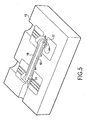
- the method therefore consists in ensuring the casting of a metal around the core 10 to completely envelop it in order to obtain a blank 18 as illustrated in FIG. Fig. 5 .
- the core 10 is completely wrapped except the exhaust ducts 11 when they are present.
- the method according to the invention aims to seal the blank 18 so that the core 10 is completely isolated vis-à-vis the external environment.
- the sealing of the blank 18 is ensured by sealing each gas evacuation duct 11 with a closure element 20 of all types ( Fig. 6 ) .
- This closure member 20 can be made in any suitable manner by a metal plug, resin, plastic or ceramic. In this way, the core 10 is not in contact with the air.
- the method consists in closing off each gas evacuation duct 11 with the aid of a stiffening element 20 filling the duct.
- this element 20 may be a rod or a metal shaft completely filling each gas discharge duct 11. This element makes it possible to stiffen and seal each gas evacuation duct 11.
- the method according to the invention is then to ensure the forging of the blank 18 to obtain the piece to the desired shape.
- This forging operation is performed either cold or hot.
- the blank 18 is preheated before being placed as illustrated in FIG. Fig. 7 , In a matrix 22 of a forging press.
- the blank 18 is thus positioned between the two dies of a forging press of all known types.
- the core 10 still present in the blank 18, makes it possible to ensure against-pressure avoiding a collapse of the part at the recess 7, during the striking operation.
- the core 10 thus ensures a level of compression adapted to obtain good mechanical strength characteristics. It should be noted that the presence of the metal pins 20 inside the core 10 also contributes to the strength of the core.
- the piece 1 is removed from the dies as illustrated in FIG. Fig. 8 . If the piece 1 has a burr 22 due to the forging operation, then this burr 22 is removed.
- the method according to the invention then consists in ensuring the breaking of the core 10 of the part 1 to obtain the hollow forging.
- This stripping operation may be performed by any appropriate means such as drilling, vibration and / or heat treatment to remove the entire core 10. For example, it may be envisaged to drill at the heads 3 in order to get bores 4 ( Fig. 9 ) and a heat treatment to remove the core located in the arm 2 to obtain the recess 7. After the total removal of the core 10, the hollow part 1 is obtained ( Fig. 1 ).
- the method according to the invention makes it possible to obtain a hollow forged part.
- the part 1 is a connecting rod. It is clear that the object of the invention can be implemented for different parts with various shapes with one or more opening recesses.
Landscapes
- Engineering & Computer Science (AREA)
- Mechanical Engineering (AREA)
- Forging (AREA)
- Molds, Cores, And Manufacturing Methods Thereof (AREA)
Claims (8)
- Verfahren zur Herstellung von hohlen Schmiedeteilen (1), dadurch gekennzeichnet, daß es die folgenden Schritte umfaßt:- Herstellen eines Kerns (10) aus Einwegmaterial, dessen Form der Innenform des zu erhaltenden Teils, bis auf die während des Schmiedens erfahrene Verformung, entspricht,- Positionieren des Kerns (10) in einer Gußform,- Formen eines Metalls um den Kern (10) herum, um den Kern - für den Erhalt eines Rohlings (18) - vollständig zu umhüllen,- Abdichten des Rohlings (18), so daß der Kern (10) vollständig gegenüber der Außenseite isoliert ist,- Schmieden des Rohlings (18), um das Teil mit der gewünschten Form zu erhalten, und- Entfernen des Kerns (10) aus dem Teil, um das hohle Schmiedeteil (1) zu erhalten.
- Verfahren nach Anspruch 1, dadurch gekennzeichnet, daß es darin besteht, den Kern (10) mit wenigstens einer Gasabzugsleitung (11) zu versehen.
- Verfahren nach Anspruch 2, dadurch gekennzeichnet, daß es darin besteht, das Positionieren des Kerns (10) in der Form mit Hilfe der Gasabzugsleitung (11) sicherzustellen.
- Verfahren nach Anspruch 2, dadurch gekennzeichnet, daß es darin besteht, die Dichtigkeit des Rohlings (18) dadurch sicherzustellen, daß jede Gasabzugsleitung (11) verschlossen wird.
- Verfahren nach Anspruch 4, dadurch gekennzeichnet, daß es darin besteht, jede Gasabzugsleitung (11) mit Hilfe eines die Leitung ausfüllenden Versteifungselements (20) zu verschließen.
- Verfahren nach einem der Ansprüche 2 bis 5, dadurch gekennzeichnet, daß es darin besteht, die Gasabzugsleitung (11) in dem Kern (10) an einer Stelle zu positionieren, die dazu bestimmt ist, eine Aufnahme (4) für das Teil zu bilden.
- Verfahren nach Anspruch 6, dadurch gekennzeichnet, daß es darin besteht, die Gasabzugsleitung (11) zu positionieren, damit sie sich auf beiden Seiten des Kerns derart vorspringend erstreckt, daß eine durchgehende Aufnahme (4) in dem Teil gebildet wird.
- Verfahren nach Anspruch 1, dadurch gekennzeichnet, daß es darin besteht, das Vorerhitzen des Rohlings (18) vor dessen Schmieden sicherzustellen.
Applications Claiming Priority (2)
| Application Number | Priority Date | Filing Date | Title |
|---|---|---|---|
| FR0757922A FR2921574B1 (fr) | 2007-09-28 | 2007-09-28 | Procede de fabrication de pieces forgees creuses et pieces ainsi obtenues |
| PCT/FR2008/051720 WO2009050382A2 (fr) | 2007-09-28 | 2008-09-26 | Procede de fabrication de pieces forgees creuses et pieces ainsi obtenues |
Publications (2)
| Publication Number | Publication Date |
|---|---|
| EP2197606A2 EP2197606A2 (de) | 2010-06-23 |
| EP2197606B1 true EP2197606B1 (de) | 2011-09-21 |
Family
ID=39321470
Family Applications (1)
| Application Number | Title | Priority Date | Filing Date |
|---|---|---|---|
| EP08840711A Ceased EP2197606B1 (de) | 2007-09-28 | 2008-09-26 | Verfahren zur herstellung hohler schmiedeteile |
Country Status (5)
| Country | Link |
|---|---|
| EP (1) | EP2197606B1 (de) |
| CN (1) | CN101808762B (de) |
| AT (1) | ATE525151T1 (de) |
| FR (1) | FR2921574B1 (de) |
| WO (1) | WO2009050382A2 (de) |
Families Citing this family (4)
| Publication number | Priority date | Publication date | Assignee | Title |
|---|---|---|---|---|
| FR2958193B1 (fr) | 2010-04-06 | 2012-06-29 | Saint Jean Ind | Procede de fabrication de pieces forgees en alliage leger incorporant des sections pleines ou tirees d'epaisseur |
| FR2969516B1 (fr) * | 2010-12-23 | 2013-08-16 | Saint Jean Ind | Procede de fabrication de noyau de sel par compaction isostatique uilisable en fonderie ou en fonderie-forgeage |
| CN106925720A (zh) * | 2017-04-17 | 2017-07-07 | 大连旅桑实业有限公司 | 一种用于铸造长手臂型铸件的砂型模具 |
| CN111842749A (zh) * | 2020-07-13 | 2020-10-30 | 中国船舶工业集团公司第七0八研究所 | 一种通用的船用钢结构的制作方法 |
Family Cites Families (8)
| Publication number | Priority date | Publication date | Assignee | Title |
|---|---|---|---|---|
| DE1938526A1 (de) * | 1969-07-29 | 1971-02-18 | Ideal Standard | Verfahren zur Herstellung von Kernen mit Entlueftungskanaelen |
| JPS5554259A (en) * | 1978-10-18 | 1980-04-21 | Hitachi Metals Ltd | Mold casting method |
| JPS56114554A (en) * | 1980-02-13 | 1981-09-09 | Hitachi Metals Ltd | Mold |
| JPS6076249A (ja) * | 1983-09-30 | 1985-04-30 | Toyota Motor Corp | 砂中子 |
| JPH05146841A (ja) * | 1991-11-27 | 1993-06-15 | Toyota Motor Corp | 鍛造方法 |
| JP3248676B2 (ja) * | 1996-12-27 | 2002-01-21 | 株式会社シマノ | 自転車用クランクとその製造方法 |
| JP3149374B2 (ja) * | 1996-12-27 | 2001-03-26 | 株式会社シマノ | 自転車用中空クランクとその製造方法 |
| CN1057716C (zh) * | 1997-02-18 | 2000-10-25 | 曾绍谦 | 能简易取出心轴的冷锻用模心装置及其使用方法 |
-
2007
- 2007-09-28 FR FR0757922A patent/FR2921574B1/fr not_active Expired - Fee Related
-
2008
- 2008-09-26 WO PCT/FR2008/051720 patent/WO2009050382A2/fr not_active Ceased
- 2008-09-26 AT AT08840711T patent/ATE525151T1/de not_active IP Right Cessation
- 2008-09-26 EP EP08840711A patent/EP2197606B1/de not_active Ceased
- 2008-09-26 CN CN200880107675.9A patent/CN101808762B/zh not_active Expired - Fee Related
Also Published As
| Publication number | Publication date |
|---|---|
| WO2009050382A2 (fr) | 2009-04-23 |
| FR2921574B1 (fr) | 2010-04-16 |
| ATE525151T1 (de) | 2011-10-15 |
| FR2921574A1 (fr) | 2009-04-03 |
| CN101808762A (zh) | 2010-08-18 |
| CN101808762B (zh) | 2013-02-20 |
| WO2009050382A3 (fr) | 2009-06-11 |
| EP2197606A2 (de) | 2010-06-23 |
Similar Documents
| Publication | Publication Date | Title |
|---|---|---|
| EP2585721B1 (de) | Verfahren zur fertigung des metallischen schutzschildes einer turbomaschinenschaufel | |
| CA2954024C (fr) | Procede de fabrication d'une aube bi-composant pour moteur a turbine a gaz et aube obtenue par un tel procede | |
| EP2555886B1 (de) | Verfahren zur herstellung von geschmiedeten werkstücken aus leichtmetalllegierung mit voll- und hohl-querschnitten | |
| CA2493445C (fr) | Piece mecanique, et procede de fabrication d'une telle piece mecanique | |
| FR2572394A1 (fr) | Procede de fabrication d'un anneau de turbine en ceramique integre a un support metallique annulaire | |
| FR3041889A1 (fr) | Procede de fabrication additive comprenant une etape de pressage isostatique a chaud | |
| EP2197606A2 (de) | Verfahren zur herstellung hohler schmiedeteile und auf diese weise gewonnene teile | |
| CA2921901C (fr) | Procede de conformage a haute temperature d'un renfort metallique d'aube | |
| FR3073760A1 (fr) | Élément à insérer et son procédé de fabrication | |
| CA2887335C (fr) | Procede de fabrication d'au moins une piece metallique de turbomachine | |
| FR2874339A1 (fr) | Procede de fabrication de pieces constitutives d'une aube creuse par forage sur presse | |
| EP1693127B1 (de) | Verfahren zum Kneten von Metallknüppeln und Anordnung eines Mantels und eines Deckels zur Durchführung des Verfahrens | |
| CH622857A5 (de) | ||
| EP0598664B1 (de) | Pleuelstange aus zwei Teilen, die aufeinander befestigt sind | |
| FR2828122A1 (fr) | Procede et appareil pour fabriquer un rotor de compresseur de suralimentation | |
| EP0586314B1 (de) | Verfahren zum Herstellen von Stücken aus Gusslegierungen mit verstärkten Teilen | |
| FR2474908A1 (fr) | Procede et dispositif d'extrusion en chambre fermee pour configurer une tige en metal en une piece en forme de tulipe | |
| EP1470889A1 (de) | Verfahren zur Herstellung eines Kolbens, Werkzeug zur Durchführung des Verfahrens und dadurch hergestellter Kolben | |
| FR2748677A1 (fr) | Procede de forgeage a froid pour fabriquer des moyeux d'embrayages de vehicules automobiles | |
| FR2888288A3 (fr) | Cloison de separation pour conduit d'admission de culasse realisee venue de matiere par moulage avec la culasse | |
| FR3036048A1 (fr) | Procede de fonderie avec moule permanent | |
| BE499042A (de) | ||
| FR2738508A1 (fr) | Procede de forgeage d'une bielle secable et bielle obtenue par ce procede | |
| FR3108539A1 (fr) | Procede de solidification dirigee pour alliages metalliques et modele en materiau eliminable pour le procede | |
| FR2965596A1 (fr) | Procede de fabrication de bielle par forgeage |
Legal Events
| Date | Code | Title | Description |
|---|---|---|---|
| PUAI | Public reference made under article 153(3) epc to a published international application that has entered the european phase |
Free format text: ORIGINAL CODE: 0009012 |
|
| 17P | Request for examination filed |
Effective date: 20100316 |
|
| AK | Designated contracting states |
Kind code of ref document: A2 Designated state(s): AT BE BG CH CY CZ DE DK EE ES FI FR GB GR HR HU IE IS IT LI LT LU LV MC MT NL NO PL PT RO SE SI SK TR |
|
| AX | Request for extension of the european patent |
Extension state: AL BA MK RS |
|
| 17Q | First examination report despatched |
Effective date: 20101102 |
|
| GRAP | Despatch of communication of intention to grant a patent |
Free format text: ORIGINAL CODE: EPIDOSNIGR1 |
|
| RTI1 | Title (correction) |
Free format text: METHOD FOR PRODUCING HOLLOW FORGED PARTS |
|
| DAX | Request for extension of the european patent (deleted) | ||
| GRAS | Grant fee paid |
Free format text: ORIGINAL CODE: EPIDOSNIGR3 |
|
| GRAA | (expected) grant |
Free format text: ORIGINAL CODE: 0009210 |
|
| AK | Designated contracting states |
Kind code of ref document: B1 Designated state(s): AT BE BG CH CY CZ DE DK EE ES FI FR GB GR HR HU IE IS IT LI LT LU LV MC MT NL NO PL PT RO SE SI SK TR |
|
| REG | Reference to a national code |
Ref country code: GB Ref legal event code: FG4D Free format text: NOT ENGLISH |
|
| REG | Reference to a national code |
Ref country code: CH Ref legal event code: EP |
|
| REG | Reference to a national code |
Ref country code: IE Ref legal event code: FG4D Free format text: LANGUAGE OF EP DOCUMENT: FRENCH |
|
| REG | Reference to a national code |
Ref country code: DE Ref legal event code: R096 Ref document number: 602008010049 Country of ref document: DE Effective date: 20111201 |
|
| REG | Reference to a national code |
Ref country code: NL Ref legal event code: VDEP Effective date: 20110921 |
|
| PG25 | Lapsed in a contracting state [announced via postgrant information from national office to epo] |
Ref country code: HR Free format text: LAPSE BECAUSE OF FAILURE TO SUBMIT A TRANSLATION OF THE DESCRIPTION OR TO PAY THE FEE WITHIN THE PRESCRIBED TIME-LIMIT Effective date: 20110921 Ref country code: SE Free format text: LAPSE BECAUSE OF FAILURE TO SUBMIT A TRANSLATION OF THE DESCRIPTION OR TO PAY THE FEE WITHIN THE PRESCRIBED TIME-LIMIT Effective date: 20110921 Ref country code: NO Free format text: LAPSE BECAUSE OF FAILURE TO SUBMIT A TRANSLATION OF THE DESCRIPTION OR TO PAY THE FEE WITHIN THE PRESCRIBED TIME-LIMIT Effective date: 20111221 Ref country code: LT Free format text: LAPSE BECAUSE OF FAILURE TO SUBMIT A TRANSLATION OF THE DESCRIPTION OR TO PAY THE FEE WITHIN THE PRESCRIBED TIME-LIMIT Effective date: 20110921 Ref country code: FI Free format text: LAPSE BECAUSE OF FAILURE TO SUBMIT A TRANSLATION OF THE DESCRIPTION OR TO PAY THE FEE WITHIN THE PRESCRIBED TIME-LIMIT Effective date: 20110921 |
|
| REG | Reference to a national code |
Ref country code: CH Ref legal event code: NV Representative=s name: BOVARD AG |
|
| LTIE | Lt: invalidation of european patent or patent extension |
Effective date: 20110921 |
|
| PG25 | Lapsed in a contracting state [announced via postgrant information from national office to epo] |
Ref country code: SI Free format text: LAPSE BECAUSE OF FAILURE TO SUBMIT A TRANSLATION OF THE DESCRIPTION OR TO PAY THE FEE WITHIN THE PRESCRIBED TIME-LIMIT Effective date: 20110921 Ref country code: LV Free format text: LAPSE BECAUSE OF FAILURE TO SUBMIT A TRANSLATION OF THE DESCRIPTION OR TO PAY THE FEE WITHIN THE PRESCRIBED TIME-LIMIT Effective date: 20110921 Ref country code: CY Free format text: LAPSE BECAUSE OF FAILURE TO SUBMIT A TRANSLATION OF THE DESCRIPTION OR TO PAY THE FEE WITHIN THE PRESCRIBED TIME-LIMIT Effective date: 20110921 Ref country code: GR Free format text: LAPSE BECAUSE OF FAILURE TO SUBMIT A TRANSLATION OF THE DESCRIPTION OR TO PAY THE FEE WITHIN THE PRESCRIBED TIME-LIMIT Effective date: 20111222 Ref country code: AT Free format text: LAPSE BECAUSE OF FAILURE TO SUBMIT A TRANSLATION OF THE DESCRIPTION OR TO PAY THE FEE WITHIN THE PRESCRIBED TIME-LIMIT Effective date: 20110921 |
|
| REG | Reference to a national code |
Ref country code: AT Ref legal event code: MK05 Ref document number: 525151 Country of ref document: AT Kind code of ref document: T Effective date: 20110921 |
|
| BERE | Be: lapsed |
Owner name: C2FT Effective date: 20110930 |
|
| REG | Reference to a national code |
Ref country code: IE Ref legal event code: FD4D |
|
| PG25 | Lapsed in a contracting state [announced via postgrant information from national office to epo] |
Ref country code: MC Free format text: LAPSE BECAUSE OF NON-PAYMENT OF DUE FEES Effective date: 20110930 Ref country code: SK Free format text: LAPSE BECAUSE OF FAILURE TO SUBMIT A TRANSLATION OF THE DESCRIPTION OR TO PAY THE FEE WITHIN THE PRESCRIBED TIME-LIMIT Effective date: 20110921 Ref country code: IE Free format text: LAPSE BECAUSE OF FAILURE TO SUBMIT A TRANSLATION OF THE DESCRIPTION OR TO PAY THE FEE WITHIN THE PRESCRIBED TIME-LIMIT Effective date: 20110921 Ref country code: CZ Free format text: LAPSE BECAUSE OF FAILURE TO SUBMIT A TRANSLATION OF THE DESCRIPTION OR TO PAY THE FEE WITHIN THE PRESCRIBED TIME-LIMIT Effective date: 20110921 Ref country code: IS Free format text: LAPSE BECAUSE OF FAILURE TO SUBMIT A TRANSLATION OF THE DESCRIPTION OR TO PAY THE FEE WITHIN THE PRESCRIBED TIME-LIMIT Effective date: 20120121 |
|
| PG25 | Lapsed in a contracting state [announced via postgrant information from national office to epo] |
Ref country code: EE Free format text: LAPSE BECAUSE OF FAILURE TO SUBMIT A TRANSLATION OF THE DESCRIPTION OR TO PAY THE FEE WITHIN THE PRESCRIBED TIME-LIMIT Effective date: 20110921 Ref country code: NL Free format text: LAPSE BECAUSE OF FAILURE TO SUBMIT A TRANSLATION OF THE DESCRIPTION OR TO PAY THE FEE WITHIN THE PRESCRIBED TIME-LIMIT Effective date: 20110921 Ref country code: PL Free format text: LAPSE BECAUSE OF FAILURE TO SUBMIT A TRANSLATION OF THE DESCRIPTION OR TO PAY THE FEE WITHIN THE PRESCRIBED TIME-LIMIT Effective date: 20110921 Ref country code: RO Free format text: LAPSE BECAUSE OF FAILURE TO SUBMIT A TRANSLATION OF THE DESCRIPTION OR TO PAY THE FEE WITHIN THE PRESCRIBED TIME-LIMIT Effective date: 20110921 Ref country code: PT Free format text: LAPSE BECAUSE OF FAILURE TO SUBMIT A TRANSLATION OF THE DESCRIPTION OR TO PAY THE FEE WITHIN THE PRESCRIBED TIME-LIMIT Effective date: 20120123 |
|
| PG25 | Lapsed in a contracting state [announced via postgrant information from national office to epo] |
Ref country code: BE Free format text: LAPSE BECAUSE OF NON-PAYMENT OF DUE FEES Effective date: 20110930 |
|
| PLBE | No opposition filed within time limit |
Free format text: ORIGINAL CODE: 0009261 |
|
| STAA | Information on the status of an ep patent application or granted ep patent |
Free format text: STATUS: NO OPPOSITION FILED WITHIN TIME LIMIT |
|
| PG25 | Lapsed in a contracting state [announced via postgrant information from national office to epo] |
Ref country code: DK Free format text: LAPSE BECAUSE OF FAILURE TO SUBMIT A TRANSLATION OF THE DESCRIPTION OR TO PAY THE FEE WITHIN THE PRESCRIBED TIME-LIMIT Effective date: 20110921 |
|
| 26N | No opposition filed |
Effective date: 20120622 |
|
| REG | Reference to a national code |
Ref country code: DE Ref legal event code: R097 Ref document number: 602008010049 Country of ref document: DE Effective date: 20120622 |
|
| PG25 | Lapsed in a contracting state [announced via postgrant information from national office to epo] |
Ref country code: MT Free format text: LAPSE BECAUSE OF FAILURE TO SUBMIT A TRANSLATION OF THE DESCRIPTION OR TO PAY THE FEE WITHIN THE PRESCRIBED TIME-LIMIT Effective date: 20110921 |
|
| PG25 | Lapsed in a contracting state [announced via postgrant information from national office to epo] |
Ref country code: ES Free format text: LAPSE BECAUSE OF FAILURE TO SUBMIT A TRANSLATION OF THE DESCRIPTION OR TO PAY THE FEE WITHIN THE PRESCRIBED TIME-LIMIT Effective date: 20120101 |
|
| PG25 | Lapsed in a contracting state [announced via postgrant information from national office to epo] |
Ref country code: LU Free format text: LAPSE BECAUSE OF NON-PAYMENT OF DUE FEES Effective date: 20110926 |
|
| PG25 | Lapsed in a contracting state [announced via postgrant information from national office to epo] |
Ref country code: BG Free format text: LAPSE BECAUSE OF FAILURE TO SUBMIT A TRANSLATION OF THE DESCRIPTION OR TO PAY THE FEE WITHIN THE PRESCRIBED TIME-LIMIT Effective date: 20111221 |
|
| PG25 | Lapsed in a contracting state [announced via postgrant information from national office to epo] |
Ref country code: TR Free format text: LAPSE BECAUSE OF FAILURE TO SUBMIT A TRANSLATION OF THE DESCRIPTION OR TO PAY THE FEE WITHIN THE PRESCRIBED TIME-LIMIT Effective date: 20110921 |
|
| PG25 | Lapsed in a contracting state [announced via postgrant information from national office to epo] |
Ref country code: HU Free format text: LAPSE BECAUSE OF FAILURE TO SUBMIT A TRANSLATION OF THE DESCRIPTION OR TO PAY THE FEE WITHIN THE PRESCRIBED TIME-LIMIT Effective date: 20110921 |
|
| REG | Reference to a national code |
Ref country code: FR Ref legal event code: PLFP Year of fee payment: 9 |
|
| REG | Reference to a national code |
Ref country code: FR Ref legal event code: PLFP Year of fee payment: 10 |
|
| REG | Reference to a national code |
Ref country code: FR Ref legal event code: PLFP Year of fee payment: 11 |
|
| PGFP | Annual fee paid to national office [announced via postgrant information from national office to epo] |
Ref country code: IT Payment date: 20210910 Year of fee payment: 14 Ref country code: CH Payment date: 20210920 Year of fee payment: 14 Ref country code: FR Payment date: 20210930 Year of fee payment: 14 |
|
| PGFP | Annual fee paid to national office [announced via postgrant information from national office to epo] |
Ref country code: GB Payment date: 20210928 Year of fee payment: 14 Ref country code: DE Payment date: 20210908 Year of fee payment: 14 |
|
| REG | Reference to a national code |
Ref country code: DE Ref legal event code: R082 Ref document number: 602008010049 Country of ref document: DE Representative=s name: CBDL PATENTANWAELTE GBR, DE |
|
| REG | Reference to a national code |
Ref country code: DE Ref legal event code: R119 Ref document number: 602008010049 Country of ref document: DE |
|
| REG | Reference to a national code |
Ref country code: CH Ref legal event code: PL |
|
| GBPC | Gb: european patent ceased through non-payment of renewal fee |
Effective date: 20220926 |
|
| PG25 | Lapsed in a contracting state [announced via postgrant information from national office to epo] |
Ref country code: LI Free format text: LAPSE BECAUSE OF NON-PAYMENT OF DUE FEES Effective date: 20220930 Ref country code: FR Free format text: LAPSE BECAUSE OF NON-PAYMENT OF DUE FEES Effective date: 20220930 Ref country code: DE Free format text: LAPSE BECAUSE OF NON-PAYMENT OF DUE FEES Effective date: 20230401 Ref country code: CH Free format text: LAPSE BECAUSE OF NON-PAYMENT OF DUE FEES Effective date: 20220930 |
|
| PG25 | Lapsed in a contracting state [announced via postgrant information from national office to epo] |
Ref country code: IT Free format text: LAPSE BECAUSE OF NON-PAYMENT OF DUE FEES Effective date: 20220926 Ref country code: GB Free format text: LAPSE BECAUSE OF NON-PAYMENT OF DUE FEES Effective date: 20220926 |