EP2197628B1 - Tete de doucissage pour machine de doucissage pour plaques de verre - Google Patents
Tete de doucissage pour machine de doucissage pour plaques de verre Download PDFInfo
- Publication number
- EP2197628B1 EP2197628B1 EP07827683.9A EP07827683A EP2197628B1 EP 2197628 B1 EP2197628 B1 EP 2197628B1 EP 07827683 A EP07827683 A EP 07827683A EP 2197628 B1 EP2197628 B1 EP 2197628B1
- Authority
- EP
- European Patent Office
- Prior art keywords
- grinding
- grinding wheel
- slabs
- spindle
- supported
- Prior art date
- Legal status (The legal status is an assumption and is not a legal conclusion. Google has not performed a legal analysis and makes no representation as to the accuracy of the status listed.)
- Active
Links
Images


Classifications
-
- B—PERFORMING OPERATIONS; TRANSPORTING
- B24—GRINDING; POLISHING
- B24B—MACHINES, DEVICES, OR PROCESSES FOR GRINDING OR POLISHING; DRESSING OR CONDITIONING OF ABRADING SURFACES; FEEDING OF GRINDING, POLISHING, OR LAPPING AGENTS
- B24B41/00—Component parts such as frames, beds, carriages, headstocks
- B24B41/04—Headstocks; Working-spindles; Features relating thereto
- B24B41/047—Grinding heads for working on plane surfaces
- B24B41/053—Grinding heads for working on plane surfaces for grinding or polishing glass
-
- B—PERFORMING OPERATIONS; TRANSPORTING
- B24—GRINDING; POLISHING
- B24B—MACHINES, DEVICES, OR PROCESSES FOR GRINDING OR POLISHING; DRESSING OR CONDITIONING OF ABRADING SURFACES; FEEDING OF GRINDING, POLISHING, OR LAPPING AGENTS
- B24B9/00—Machines or devices designed for grinding edges or bevels on work or for removing burrs; Accessories therefor
- B24B9/02—Machines or devices designed for grinding edges or bevels on work or for removing burrs; Accessories therefor characterised by a special design with respect to properties of materials specific to articles to be ground
- B24B9/06—Machines or devices designed for grinding edges or bevels on work or for removing burrs; Accessories therefor characterised by a special design with respect to properties of materials specific to articles to be ground of non-metallic inorganic material, e.g. stone, ceramics, porcelain
- B24B9/08—Machines or devices designed for grinding edges or bevels on work or for removing burrs; Accessories therefor characterised by a special design with respect to properties of materials specific to articles to be ground of non-metallic inorganic material, e.g. stone, ceramics, porcelain of glass
- B24B9/10—Machines or devices designed for grinding edges or bevels on work or for removing burrs; Accessories therefor characterised by a special design with respect to properties of materials specific to articles to be ground of non-metallic inorganic material, e.g. stone, ceramics, porcelain of glass of plate glass
- B24B9/102—Machines or devices designed for grinding edges or bevels on work or for removing burrs; Accessories therefor characterised by a special design with respect to properties of materials specific to articles to be ground of non-metallic inorganic material, e.g. stone, ceramics, porcelain of glass of plate glass for travelling sheets
Definitions
- the present invention refers to a grinding head for a rectilinear grinding machine.
- the grinding plants being used comprise a conveyor adapted to advance the glass slabs along an horizontal path through one or more working stations, each one of which houses a plurality of grinding wheels arranged in fixed positions along the path itself in order to grind two mutually opposite sides of the perimeter edge when advancing each slab.
- patent EP-A-1468784 (which forms the preamble of Claim 1), related to a grinding head 1 (see right side of Fig. 1 ) that allows accurately working each glass slab 2 in a working station where the slab 2 itself is kept in a univocal fixed reference position when working its related edge.
- a plurality of grinding heads 1 like the one disclosed in the above patent, are adapted to simultaneously work on all sides the glass slabs 2, through workings that are mutually different and are also operating at different speeds.
- the described grinding head 1 as shown in Fig.
- a grinding wheel 20 for the side grinding of the slab 2; a grinding wheel 22 for grinding the upper threads (or bevels) of the slab 2; a grinding wheel 24 for polishing the upper threads (or bevels) of the slab 2; a grinding wheel 26 for grinding the lower threads (or bevels) of the slab 2; a grinding wheel 28 for polishing the lower threads (or bevels) of the slab 2; and two grinding wheels 30, 32 for the side polishing of the slab 2. All grinding wheels 20 to 32 are supported and rotatingly driven by a respective spindle (not shown), and the grinding wheels 20 to 32 and their respective spindles are contained in and supported by a supporting structure 9.
- object of the present invention is solving the above prior art problems, by providing a grinding head equipped with an innovative grinding assembly, that allows on one hand to use grinding wheels with a very big diameter (on the order of 200 mm, but that can be adjusted and increased at will) and on the other hand to only minimally increase the width encumbrance of the head, exploiting the thickness, rather than the width, of the grinding wheel of which the inventive assembly is composed.
- the grinding wheel of the inventive assembly works tangentially on the glass edge, and has it rotation axis parallel to the edge to be ground, differently from all other currently known grinding wheels, whose rotation axis is perpendicular or slanted with respect to the glass edge.
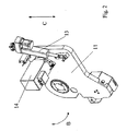
- the inventive assembly 3 is equipped with at least one diamond grinding wheel 5 that tangentially operates on the glass edge 2 and whose rotation axis A is parallel to the edge of the glass 2 to be ground.
- the assembly 3 allows saving a lot of space in its encumbrance, that is equal to the thickness of the grinding wheel 5, instead of its diameter, that can be thereby equal to 200 mm or more.
- the removal of the grinding wheel 5 is adjusted by moving the grinding wheel 5 itself along the glass 2 direction (as known), through any handling system, in an oscillating way (direction B in Fig. 2 ) or in parallel (direction C in Fig. 2 ) to the plane of the slab 2 to be worked.
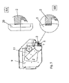
- Figures 2 and 3 show a preferred, but absolutely not limiting, embodiment of the handling system of the grinding wheel 5, that can be suitably adapted to the head 1 of Fig. 1 .
- Such system substantially comprises a cam-shaped supporting element 11 equipped with pushing means 13 (typically a ball re-circulation screw driven by a stepped motor or any other motor) adapted to push the supporting element 11 in operating directions B and C in Fig. 2 .
- the system comprises an actuating motor 14 shown in Fig. 3 , adapted to transmit the rotary motion to the grinding wheel 5 through a system with belt 16 and pulleys 18, 19.
- the particular arrangement of the above mentioned handling system allows housing the main bearings 40 of the grinding wheel 5 directly inside it (as can be seen in Fig. 3 ), greatly reducing the projection of the grinding wheel 5 with respect to a traditional grinding spindle.
- the grinding assembly 3 of the present invention can be used by moving the grinding wheel 5 along the direction of the edge of the slab 2 to be ground, or by keeping the grinding assembly fixed and moving the slab 2, for example along the direction designated with D in Fig. 1 .
- the grinding wheel 5 if suitably shaped at 45°, as can be seen in the drawings, also allows performing a bevel on the edge of the glass 2 (operation that is more and more required by the market due to accident-preventing issues). Traditionally, this operation was performed by an additional grinding wheel, that operated as follower and performed an irregular (rounded) and scarcely accurate bevel.
- FIG. 4 where, starting from the position designated with 1, the grinding wheel 7 is moved next to the angle to be worked with a movement along direction F. As can be seen in position 2, the grinding wheel 7 obtains a bevel with an operating advancement movement along direction E, while afterwards it is quickly moved away through a movement along direction G, until (position 3) the grinding wheel 5 is exactly in the correct position to engage the glass slab 2 by - advancing along direction F, performing the bevel cutting at the desired thickness, together with the usual grinding operation of the slab 2.
- the grinding wheel 5 of the invention performs, as can be better seen in Fig. 5 , a removal of material with a slight curve (Step SB in Fig. 5 ); such slight curve is afterwards easily removed by the traditional grinding wheel 20 for side grinding (Step SA in Fig. 5 ), thereby efficiently completing the grinding work of the slab 2 with a minimum global encumbrance.
- the grinding head 1 of the present invention allows providing a great capacity of removing material from a glass slab 2 of any size, with a really minimum additional encumbrance with respect to traditional heads.
- the thereby shown grinding head 1 allows performing, on a fixed glass slab 2, a plurality of grinding and polishing operations, by driving the grinding wheels and their related spindles at mutually different speeds and by placing the grinding wheels next to different parts of the slab 2 on which it is necessary to perform the relevant working.
Landscapes
- Engineering & Computer Science (AREA)
- Mechanical Engineering (AREA)
- Chemical & Material Sciences (AREA)
- Ceramic Engineering (AREA)
- Inorganic Chemistry (AREA)
- Grinding And Polishing Of Tertiary Curved Surfaces And Surfaces With Complex Shapes (AREA)
- Grinding Of Cylindrical And Plane Surfaces (AREA)
Claims (8)
- Tête de meulage (1) pour une machine de meulage de plaques en verre (2) comprenant :- une structure de support (9) ;- au moins une meule (20) pour le meulage latéral des plaques (2) qui est soutenue et commandée en rotation par une broche, où cette meule (20) et cette broche sont contenues dans la structure de support (9) et sont soutenues par celle-ci ;- au moins une meule (22) pour le meulage des filets supérieurs des plaques (2) qui est soutenue et commandée en rotation par une broche, où cette meule (22) et cette broche sont contenues dans la structure de support (9) et sont soutenues par celle-ci ;- au moins une meule (24) pour le polissage des filets supérieurs des plaques (2) qui est soutenue et commandée en rotation par une broche, où cette meule (24) et cette broche sont contenues dans la structure de support (9) et sont soutenues par celle-ci ;- au moins une meule (26) pour le meulage des filets inférieurs des plaques (2) qui est soutenue et commandée en rotation par une broche, où cette meule (26) et cette broche sont contenues dans la structure de support (9) et sont soutenues par celle-ci ;- au moins une meule (28) pour le polissage des filets inférieurs des plaques (2) qui est soutenue et commandée en rotation par une broche, où cette meule (28) et cette broche sont contenues dans la structure de support (9) et sont soutenues par celle-ci ;- au moins une meule (30, 32) pour le polissage latéral des plaques (2) qui est soutenue et commandée en rotation par une broche, où cette meule (30, 32) et cette broche sont contenues dans la structure de support (9) et sont soutenues par celle-ci ;- les susdites meules (20, 30, 32) pour le meulage et le polissage latéral tournent, de manière indépendante l'une de l'autre, autour d'un axe qui est perpendiculaire à une bordure des plaques (2) ; les susdites meules (22, 24, 26, 28) pour le meulage et le polissage des filets supérieur et inférieur des plaques (2) tournent, de manière indépendante l'une de l'autre, autour d'un axe qui est incliné par rapport à la bordure des plaques (2) ; les susdites meules (22, 24, 26, 28) pour le meulage/polissage latéral mais aussi pour meuler et polir les filets effectuent, durant le travail, un mouvement axial le long des plaques (2), les mouvements axiaux de ces meules (22, 24, 26, 28) peuvent être actionnés individuellement,qui est caractérisée par un groupe de meulage (3) comprenant :- au moins une première meule pour le meulage (5) qui travaille de manière tangentielle sur une bordure du verre (2) et dont l'axe de rotation A est parallèle à la bordure du verre (2) à meuler, alors qu'il est perpendiculaire à l'axe de rotation des meules (20, 30, 32) pour le meulage et le polissage latéral, et qu'il est incliné par rapport à l'axe de rotation des meules (22, 24, 26, 28) pour le meulage et le polissage des filets supérieur et inférieur des plaques (2) ; ainsi que- un système de mise en mouvement de la première meule pour le meulage (5) qui actionne cette dernière pour régler l'enlèvement du verre (2) de manière basculante ou parallèle par rapport au plan de la plaque en verre (2) à meuler.
- Tête de meulage (1) selon la revendication 1, où le groupe de meulage (3) est doté au moins d'une seconde meule de meulage (7) exécutant exclusivement une opération de meulage d'un angle du verre (2), et où la première meule (5) est en mesure de couper par la suite l'angle obtenu par la seconde meule (7) selon l'épaisseur voulue.
- Tête de meulage (1) selon la revendication 1, où le système de mise en mouvement comprend :- un élément de support à came (11) doté d'outils de poussée (13) servant à pousser l'élément de support (11) dans les directions opérationnelles ;- un moteur d'actionnement (14) qui transmet le mouvement rotatoire à la meule (5) à travers un système à courroie (16) et à poulies (18, 19) ;- ce système de mise en mouvement accueille, directement à l'intérieur, les paliers de vilebrequin (40) de la meule (5).
- Tête de meulage (1) selon la revendication 1, où le système de mise en mouvement est composé de guides de commande.
- Tête de meulage (1) selon la revendication 1, où le groupe de meulage (3) déplace la meule (5) en direction de la bordure de la plaque (2) à meuler et maintient fixe cette dernière (2).
- Tête de meulage (1) selon la revendication 1, où le groupe de meulage (3) maintient fixe le groupe de meulage (3) et déplace la plaque (2).
- Tête de meulage (1) selon la revendication 1, où la surface de travail de la meule (5) est profilée à 45° pour arrondir l'angle du verre (2).
- Tête de meulage (1) selon la revendication 1, où il y a deux meules (30, 32) pour le polissage latéral qui sont commandées en rotation par leur broche respective.
Applications Claiming Priority (1)
| Application Number | Priority Date | Filing Date | Title |
|---|---|---|---|
| PCT/IT2007/000631 WO2009034588A1 (fr) | 2007-09-13 | 2007-09-13 | Ensemble de doucissage pour plaques de verre et tête de doucissage pour machine de doucissage rectiligne équipée d'un tel ensemble |
Publications (2)
| Publication Number | Publication Date |
|---|---|
| EP2197628A1 EP2197628A1 (fr) | 2010-06-23 |
| EP2197628B1 true EP2197628B1 (fr) | 2014-11-26 |
Family
ID=38705142
Family Applications (1)
| Application Number | Title | Priority Date | Filing Date |
|---|---|---|---|
| EP07827683.9A Active EP2197628B1 (fr) | 2007-09-13 | 2007-09-13 | Tete de doucissage pour machine de doucissage pour plaques de verre |
Country Status (3)
| Country | Link |
|---|---|
| US (1) | US8317571B2 (fr) |
| EP (1) | EP2197628B1 (fr) |
| WO (1) | WO2009034588A1 (fr) |
Families Citing this family (4)
| Publication number | Priority date | Publication date | Assignee | Title |
|---|---|---|---|---|
| US10864656B2 (en) * | 2017-01-20 | 2020-12-15 | Cambria Company Llc | Slab cutting apparatus and method |
| EP3581331B1 (fr) * | 2018-06-13 | 2022-07-20 | W-M GLASS Sp. z o.o. | Ensemble de disques de meulage des bords de plaques de verre |
| CN114986317A (zh) * | 2022-06-30 | 2022-09-02 | 西安奕斯伟材料科技有限公司 | 半导体边缘研磨设备和半导体的边缘研磨方法 |
| CN118752337B (zh) * | 2024-09-05 | 2024-11-26 | 苏州隆登电子科技有限公司 | 用于笔记本外壳的侧壁打磨装置 |
Family Cites Families (7)
| Publication number | Priority date | Publication date | Assignee | Title |
|---|---|---|---|---|
| JPS5493288A (en) * | 1977-12-31 | 1979-07-24 | Bando Kiko Co | Glass chamfering machine |
| US4228617A (en) * | 1977-12-31 | 1980-10-21 | Bando Kiko Co., Ltd | Method for grinding glass plates and the like through numerical control and beveling machine therefor |
| US5816897A (en) * | 1996-09-16 | 1998-10-06 | Corning Incorporated | Method and apparatus for edge finishing glass |
| US6325704B1 (en) * | 1999-06-14 | 2001-12-04 | Corning Incorporated | Method for finishing edges of glass sheets |
| IT1315616B1 (it) * | 2000-03-15 | 2003-03-14 | Luigi Pedrini | Levigatrice per materiali lapidei, dotata di teste multiple allineatesu due travi oscillanti e parallele, nonche' con distanza regolabile. |
| ITTO20030297A1 (it) | 2003-04-16 | 2004-10-17 | Forvet Srl | Testa di molatura per una macchina di molatura di |
| ITTO20040134U1 (it) * | 2004-10-21 | 2005-01-21 | Biesse Spa | Dispositivo per l'esecuzione di smussi con angolazioni variabili sugli spigoli di lastre di vetro, marmo, materiali lapidei o ceramici in genere |
-
2007
- 2007-09-13 EP EP07827683.9A patent/EP2197628B1/fr active Active
- 2007-09-13 US US12/676,865 patent/US8317571B2/en active Active
- 2007-09-13 WO PCT/IT2007/000631 patent/WO2009034588A1/fr not_active Ceased
Also Published As
| Publication number | Publication date |
|---|---|
| US8317571B2 (en) | 2012-11-27 |
| EP2197628A1 (fr) | 2010-06-23 |
| WO2009034588A1 (fr) | 2009-03-19 |
| US20100304645A1 (en) | 2010-12-02 |
Similar Documents
| Publication | Publication Date | Title |
|---|---|---|
| EP3603913B1 (fr) | Tête de coupe et de chanfreinage, machine multi-axes comprenant une telle tête de coupe et de chanfreinage et méthode de coupe et de chamfreinage | |
| CA2966681C (fr) | Machine pour couper du materiau en pierre | |
| EP1468784B1 (fr) | Tête de meulage pour une machine à meuler les feuilles de verre et machine équipée d'une telle tête de meulage | |
| EP2197628B1 (fr) | Tete de doucissage pour machine de doucissage pour plaques de verre | |
| KR101206367B1 (ko) | 윈도우 글래스 연마장치 | |
| CN101326032B (zh) | 颈部磨削装置及在该颈部磨削装置中使用的磨削装置、以及颈部磨削方法 | |
| KR101904807B1 (ko) | 광학 유리를 위한 연마 기계 및 관련 연마 방법 | |
| CN206105577U (zh) | 双头磨床 | |
| CN210818403U (zh) | 门窗型材的定位推送切割磨边装置 | |
| KR20160035323A (ko) | 석재 쌍방향 가공 장치 | |
| JP5154880B2 (ja) | ドレス装置を備えた硬質脆性板の面取装置 | |
| KR101869688B1 (ko) | 하우징 내경 연마 장치 | |
| JP2822061B2 (ja) | 長尺刃物研削盤を用いた長尺刃物の刃先研削方法 | |
| US6450864B1 (en) | End mill grinder with two independently adjustable grinding wheels | |
| CN102950513B (zh) | 一种修磨机 | |
| KR20140062213A (ko) | 안경 렌즈 가공 장치 및 방법 | |
| KR200412773Y1 (ko) | 범용 공구 연삭기의 동시 3축 제어장치 | |
| TWM482471U (zh) | 主軸內孔線上研磨機 | |
| KR100742657B1 (ko) | 범용 공구 연삭기의 동시 3축 제어장치 | |
| KR100820186B1 (ko) | 연삭기용 탈착형 면취기 | |
| JP2003266304A (ja) | 基板の研削用マルチ砥石及びこれを用いた研削装置 | |
| EP3215329A1 (fr) | Machine pour couper du matériau en pierre | |
| KR200294688Y1 (ko) | 만능 연마기의 절삭공구 캐리어의 헤드 이송장치 | |
| JP5514642B2 (ja) | 砥石及びその砥粒への逃げ面成形方法 | |
| KR20050118559A (ko) | 컬러필터의 에지 가공장치 |
Legal Events
| Date | Code | Title | Description |
|---|---|---|---|
| PUAI | Public reference made under article 153(3) epc to a published international application that has entered the european phase |
Free format text: ORIGINAL CODE: 0009012 |
|
| 17P | Request for examination filed |
Effective date: 20100308 |
|
| AK | Designated contracting states |
Kind code of ref document: A1 Designated state(s): AT BE BG CH CY CZ DE DK EE ES FI FR GB GR HU IE IS IT LI LT LU LV MC MT NL PL PT RO SE SI SK TR |
|
| AX | Request for extension of the european patent |
Extension state: AL BA HR MK RS |
|
| DAX | Request for extension of the european patent (deleted) | ||
| 17Q | First examination report despatched |
Effective date: 20140702 |
|
| GRAP | Despatch of communication of intention to grant a patent |
Free format text: ORIGINAL CODE: EPIDOSNIGR1 |
|
| INTG | Intention to grant announced |
Effective date: 20140917 |
|
| RIN1 | Information on inventor provided before grant (corrected) |
Inventor name: GARIGLIO, DAVIDE |
|
| GRAS | Grant fee paid |
Free format text: ORIGINAL CODE: EPIDOSNIGR3 |
|
| GRAA | (expected) grant |
Free format text: ORIGINAL CODE: 0009210 |
|
| AK | Designated contracting states |
Kind code of ref document: B1 Designated state(s): AT BE BG CH CY CZ DE DK EE ES FI FR GB GR HU IE IS IT LI LT LU LV MC MT NL PL PT RO SE SI SK TR |
|
| REG | Reference to a national code |
Ref country code: GB Ref legal event code: FG4D |
|
| REG | Reference to a national code |
Ref country code: CH Ref legal event code: EP |
|
| REG | Reference to a national code |
Ref country code: AT Ref legal event code: REF Ref document number: 697898 Country of ref document: AT Kind code of ref document: T Effective date: 20141215 |
|
| REG | Reference to a national code |
Ref country code: IE Ref legal event code: FG4D |
|
| REG | Reference to a national code |
Ref country code: DE Ref legal event code: R096 Ref document number: 602007039463 Country of ref document: DE Effective date: 20150108 |
|
| REG | Reference to a national code |
Ref country code: CH Ref legal event code: NV Representative=s name: MICHELI AND CIE SA, CH |
|
| REG | Reference to a national code |
Ref country code: NL Ref legal event code: VDEP Effective date: 20141126 |
|
| REG | Reference to a national code |
Ref country code: LT Ref legal event code: MG4D |
|
| PG25 | Lapsed in a contracting state [announced via postgrant information from national office to epo] |
Ref country code: ES Free format text: LAPSE BECAUSE OF FAILURE TO SUBMIT A TRANSLATION OF THE DESCRIPTION OR TO PAY THE FEE WITHIN THE PRESCRIBED TIME-LIMIT Effective date: 20141126 Ref country code: IS Free format text: LAPSE BECAUSE OF FAILURE TO SUBMIT A TRANSLATION OF THE DESCRIPTION OR TO PAY THE FEE WITHIN THE PRESCRIBED TIME-LIMIT Effective date: 20150326 Ref country code: NL Free format text: LAPSE BECAUSE OF FAILURE TO SUBMIT A TRANSLATION OF THE DESCRIPTION OR TO PAY THE FEE WITHIN THE PRESCRIBED TIME-LIMIT Effective date: 20141126 Ref country code: PT Free format text: LAPSE BECAUSE OF FAILURE TO SUBMIT A TRANSLATION OF THE DESCRIPTION OR TO PAY THE FEE WITHIN THE PRESCRIBED TIME-LIMIT Effective date: 20150326 Ref country code: LT Free format text: LAPSE BECAUSE OF FAILURE TO SUBMIT A TRANSLATION OF THE DESCRIPTION OR TO PAY THE FEE WITHIN THE PRESCRIBED TIME-LIMIT Effective date: 20141126 |
|
| PG25 | Lapsed in a contracting state [announced via postgrant information from national office to epo] |
Ref country code: SE Free format text: LAPSE BECAUSE OF FAILURE TO SUBMIT A TRANSLATION OF THE DESCRIPTION OR TO PAY THE FEE WITHIN THE PRESCRIBED TIME-LIMIT Effective date: 20141126 Ref country code: CY Free format text: LAPSE BECAUSE OF FAILURE TO SUBMIT A TRANSLATION OF THE DESCRIPTION OR TO PAY THE FEE WITHIN THE PRESCRIBED TIME-LIMIT Effective date: 20141126 Ref country code: GR Free format text: LAPSE BECAUSE OF FAILURE TO SUBMIT A TRANSLATION OF THE DESCRIPTION OR TO PAY THE FEE WITHIN THE PRESCRIBED TIME-LIMIT Effective date: 20150227 Ref country code: LV Free format text: LAPSE BECAUSE OF FAILURE TO SUBMIT A TRANSLATION OF THE DESCRIPTION OR TO PAY THE FEE WITHIN THE PRESCRIBED TIME-LIMIT Effective date: 20141126 |
|
| PG25 | Lapsed in a contracting state [announced via postgrant information from national office to epo] |
Ref country code: SK Free format text: LAPSE BECAUSE OF FAILURE TO SUBMIT A TRANSLATION OF THE DESCRIPTION OR TO PAY THE FEE WITHIN THE PRESCRIBED TIME-LIMIT Effective date: 20141126 Ref country code: EE Free format text: LAPSE BECAUSE OF FAILURE TO SUBMIT A TRANSLATION OF THE DESCRIPTION OR TO PAY THE FEE WITHIN THE PRESCRIBED TIME-LIMIT Effective date: 20141126 Ref country code: RO Free format text: LAPSE BECAUSE OF FAILURE TO SUBMIT A TRANSLATION OF THE DESCRIPTION OR TO PAY THE FEE WITHIN THE PRESCRIBED TIME-LIMIT Effective date: 20141126 Ref country code: DK Free format text: LAPSE BECAUSE OF FAILURE TO SUBMIT A TRANSLATION OF THE DESCRIPTION OR TO PAY THE FEE WITHIN THE PRESCRIBED TIME-LIMIT Effective date: 20141126 Ref country code: CZ Free format text: LAPSE BECAUSE OF FAILURE TO SUBMIT A TRANSLATION OF THE DESCRIPTION OR TO PAY THE FEE WITHIN THE PRESCRIBED TIME-LIMIT Effective date: 20141126 |
|
| REG | Reference to a national code |
Ref country code: DE Ref legal event code: R097 Ref document number: 602007039463 Country of ref document: DE |
|
| PG25 | Lapsed in a contracting state [announced via postgrant information from national office to epo] |
Ref country code: PL Free format text: LAPSE BECAUSE OF FAILURE TO SUBMIT A TRANSLATION OF THE DESCRIPTION OR TO PAY THE FEE WITHIN THE PRESCRIBED TIME-LIMIT Effective date: 20141126 |
|
| PLBE | No opposition filed within time limit |
Free format text: ORIGINAL CODE: 0009261 |
|
| STAA | Information on the status of an ep patent application or granted ep patent |
Free format text: STATUS: NO OPPOSITION FILED WITHIN TIME LIMIT |
|
| 26N | No opposition filed |
Effective date: 20150827 |
|
| REG | Reference to a national code |
Ref country code: AT Ref legal event code: UEP Ref document number: 697898 Country of ref document: AT Kind code of ref document: T Effective date: 20141126 |
|
| PG25 | Lapsed in a contracting state [announced via postgrant information from national office to epo] |
Ref country code: SI Free format text: LAPSE BECAUSE OF FAILURE TO SUBMIT A TRANSLATION OF THE DESCRIPTION OR TO PAY THE FEE WITHIN THE PRESCRIBED TIME-LIMIT Effective date: 20141126 |
|
| PG25 | Lapsed in a contracting state [announced via postgrant information from national office to epo] |
Ref country code: MC Free format text: LAPSE BECAUSE OF FAILURE TO SUBMIT A TRANSLATION OF THE DESCRIPTION OR TO PAY THE FEE WITHIN THE PRESCRIBED TIME-LIMIT Effective date: 20141126 Ref country code: LU Free format text: LAPSE BECAUSE OF FAILURE TO SUBMIT A TRANSLATION OF THE DESCRIPTION OR TO PAY THE FEE WITHIN THE PRESCRIBED TIME-LIMIT Effective date: 20150913 |
|
| GBPC | Gb: european patent ceased through non-payment of renewal fee |
Effective date: 20150913 |
|
| REG | Reference to a national code |
Ref country code: DE Ref legal event code: R082 Ref document number: 602007039463 Country of ref document: DE Representative=s name: HERNANDEZ, YORCK, DIPL.-ING., DE |
|
| REG | Reference to a national code |
Ref country code: IE Ref legal event code: MM4A |
|
| REG | Reference to a national code |
Ref country code: FR Ref legal event code: ST Effective date: 20160531 |
|
| PG25 | Lapsed in a contracting state [announced via postgrant information from national office to epo] |
Ref country code: IE Free format text: LAPSE BECAUSE OF NON-PAYMENT OF DUE FEES Effective date: 20150913 Ref country code: GB Free format text: LAPSE BECAUSE OF NON-PAYMENT OF DUE FEES Effective date: 20150913 |
|
| PG25 | Lapsed in a contracting state [announced via postgrant information from national office to epo] |
Ref country code: FR Free format text: LAPSE BECAUSE OF NON-PAYMENT OF DUE FEES Effective date: 20150930 |
|
| REG | Reference to a national code |
Ref country code: DE Ref legal event code: R081 Ref document number: 602007039463 Country of ref document: DE Owner name: FORVET R&D S.R.L., IT Free format text: FORMER OWNER: FORVET S.R.L., VOLVERA, IT Ref country code: DE Ref legal event code: R082 Ref document number: 602007039463 Country of ref document: DE Representative=s name: HERNANDEZ, YORCK, DIPL.-ING., DE |
|
| REG | Reference to a national code |
Ref country code: CH Ref legal event code: NV Representative=s name: ISLER AND PEDRAZZINI AG, CH Ref country code: CH Ref legal event code: PFA Owner name: FORVET S.P.A., IT Free format text: FORMER OWNER: FORVET S.R.L., IT Ref country code: CH Ref legal event code: PUE Owner name: FORVET R&D S.R.L., IT Free format text: FORMER OWNER: FORVET S.P.A., IT |
|
| REG | Reference to a national code |
Ref country code: AT Ref legal event code: PC Ref document number: 697898 Country of ref document: AT Kind code of ref document: T Owner name: FORVET R&D S.R.L., IT Effective date: 20170124 |
|
| PG25 | Lapsed in a contracting state [announced via postgrant information from national office to epo] |
Ref country code: MT Free format text: LAPSE BECAUSE OF FAILURE TO SUBMIT A TRANSLATION OF THE DESCRIPTION OR TO PAY THE FEE WITHIN THE PRESCRIBED TIME-LIMIT Effective date: 20141126 |
|
| PG25 | Lapsed in a contracting state [announced via postgrant information from national office to epo] |
Ref country code: HU Free format text: LAPSE BECAUSE OF FAILURE TO SUBMIT A TRANSLATION OF THE DESCRIPTION OR TO PAY THE FEE WITHIN THE PRESCRIBED TIME-LIMIT; INVALID AB INITIO Effective date: 20070913 Ref country code: BG Free format text: LAPSE BECAUSE OF FAILURE TO SUBMIT A TRANSLATION OF THE DESCRIPTION OR TO PAY THE FEE WITHIN THE PRESCRIBED TIME-LIMIT Effective date: 20141126 |
|
| PG25 | Lapsed in a contracting state [announced via postgrant information from national office to epo] |
Ref country code: TR Free format text: LAPSE BECAUSE OF FAILURE TO SUBMIT A TRANSLATION OF THE DESCRIPTION OR TO PAY THE FEE WITHIN THE PRESCRIBED TIME-LIMIT Effective date: 20141126 |
|
| PG25 | Lapsed in a contracting state [announced via postgrant information from national office to epo] |
Ref country code: BE Free format text: LAPSE BECAUSE OF FAILURE TO SUBMIT A TRANSLATION OF THE DESCRIPTION OR TO PAY THE FEE WITHIN THE PRESCRIBED TIME-LIMIT Effective date: 20141126 |
|
| REG | Reference to a national code |
Ref country code: DE Ref legal event code: R081 Ref document number: 602007039463 Country of ref document: DE Owner name: FORVET S.P.A. COSTRUZIONE MACCHINE SPECIALI, IT Free format text: FORMER OWNER: FORVET R&D S.R.L., VOLVERA, IT Ref country code: DE Ref legal event code: R082 Ref document number: 602007039463 Country of ref document: DE Representative=s name: GULDE & PARTNER PATENT- UND RECHTSANWALTSKANZL, DE |
|
| REG | Reference to a national code |
Ref country code: AT Ref legal event code: PC Ref document number: 697898 Country of ref document: AT Kind code of ref document: T Owner name: FORVET S.P.A. COSTRUZIONE MACCHINE SPECIALI, IT Effective date: 20230414 |
|
| REG | Reference to a national code |
Ref country code: CH Ref legal event code: U11 Free format text: ST27 STATUS EVENT CODE: U-0-0-U10-U11 (AS PROVIDED BY THE NATIONAL OFFICE) Effective date: 20251001 |
|
| PGFP | Annual fee paid to national office [announced via postgrant information from national office to epo] |
Ref country code: FI Payment date: 20250925 Year of fee payment: 19 |
|
| PGFP | Annual fee paid to national office [announced via postgrant information from national office to epo] |
Ref country code: DE Payment date: 20250926 Year of fee payment: 19 |
|
| PGFP | Annual fee paid to national office [announced via postgrant information from national office to epo] |
Ref country code: IT Payment date: 20250908 Year of fee payment: 19 |
|
| PGFP | Annual fee paid to national office [announced via postgrant information from national office to epo] |
Ref country code: AT Payment date: 20250917 Year of fee payment: 19 |
|
| PGFP | Annual fee paid to national office [announced via postgrant information from national office to epo] |
Ref country code: CH Payment date: 20251001 Year of fee payment: 19 |