EP2197732B1 - Dispositif de réglage d'angle pour selle de bicyclette - Google Patents
Dispositif de réglage d'angle pour selle de bicyclette Download PDFInfo
- Publication number
- EP2197732B1 EP2197732B1 EP07851808A EP07851808A EP2197732B1 EP 2197732 B1 EP2197732 B1 EP 2197732B1 EP 07851808 A EP07851808 A EP 07851808A EP 07851808 A EP07851808 A EP 07851808A EP 2197732 B1 EP2197732 B1 EP 2197732B1
- Authority
- EP
- European Patent Office
- Prior art keywords
- saddle
- angle
- coupling
- coupled
- post
- Prior art date
- Legal status (The legal status is an assumption and is not a legal conclusion. Google has not performed a legal analysis and makes no representation as to the accuracy of the status listed.)
- Not-in-force
Links
Images


Classifications
-
- B—PERFORMING OPERATIONS; TRANSPORTING
- B62—LAND VEHICLES FOR TRAVELLING OTHERWISE THAN ON RAILS
- B62J—CYCLE SADDLES OR SEATS; AUXILIARY DEVICES OR ACCESSORIES SPECIALLY ADAPTED TO CYCLES AND NOT OTHERWISE PROVIDED FOR, e.g. ARTICLE CARRIERS OR CYCLE PROTECTORS
- B62J1/00—Saddles or other seats for cycles; Arrangement thereof; Component parts
- B62J1/08—Frames for saddles; Connections between saddle frames and seat pillars; Seat pillars
-
- B—PERFORMING OPERATIONS; TRANSPORTING
- B62—LAND VEHICLES FOR TRAVELLING OTHERWISE THAN ON RAILS
- B62J—CYCLE SADDLES OR SEATS; AUXILIARY DEVICES OR ACCESSORIES SPECIALLY ADAPTED TO CYCLES AND NOT OTHERWISE PROVIDED FOR, e.g. ARTICLE CARRIERS OR CYCLE PROTECTORS
- B62J1/00—Saddles or other seats for cycles; Arrangement thereof; Component parts
-
- B—PERFORMING OPERATIONS; TRANSPORTING
- B62—LAND VEHICLES FOR TRAVELLING OTHERWISE THAN ON RAILS
- B62J—CYCLE SADDLES OR SEATS; AUXILIARY DEVICES OR ACCESSORIES SPECIALLY ADAPTED TO CYCLES AND NOT OTHERWISE PROVIDED FOR, e.g. ARTICLE CARRIERS OR CYCLE PROTECTORS
- B62J1/00—Saddles or other seats for cycles; Arrangement thereof; Component parts
- B62J1/10—Internal adjustment of saddles
-
- B—PERFORMING OPERATIONS; TRANSPORTING
- B62—LAND VEHICLES FOR TRAVELLING OTHERWISE THAN ON RAILS
- B62K—CYCLES; CYCLE FRAMES; CYCLE STEERING DEVICES; RIDER-OPERATED TERMINAL CONTROLS SPECIALLY ADAPTED FOR CYCLES; CYCLE AXLE SUSPENSIONS; CYCLE SIDECARS, FORECARS, OR THE LIKE
- B62K19/00—Cycle frames
- B62K19/30—Frame parts shaped to receive other cycle parts or accessories
- B62K19/36—Frame parts shaped to receive other cycle parts or accessories for attaching saddle pillars, e.g. adjustable during ride
-
- Y—GENERAL TAGGING OF NEW TECHNOLOGICAL DEVELOPMENTS; GENERAL TAGGING OF CROSS-SECTIONAL TECHNOLOGIES SPANNING OVER SEVERAL SECTIONS OF THE IPC; TECHNICAL SUBJECTS COVERED BY FORMER USPC CROSS-REFERENCE ART COLLECTIONS [XRACs] AND DIGESTS
- Y10—TECHNICAL SUBJECTS COVERED BY FORMER USPC
- Y10T—TECHNICAL SUBJECTS COVERED BY FORMER US CLASSIFICATION
- Y10T403/00—Joints and connections
- Y10T403/32—Articulated members
- Y10T403/32254—Lockable at fixed position
- Y10T403/32262—At selected angle
Definitions
- the present invention relates, in general, to a device for adjusting the position of a bicycle saddle and, more particularly, to an angle adjusting device for a bicycle saddle, which is coupled to the upper portion of a structure for adjusting the height of the saddle so as to adjust the angle of the bicycle saddle as desired, thus allowing the angle of the saddle to be changed so that the saddle can be appropriately positioned relative to the pedals and handlebars, depending on the size of a user's body.
- bicycles are vehicles that are moved by pushing pedals with two feet.
- bicycles include vehicles having three or four wheels and vehicles moving in places other than the ground, for example, a water bicycle or an ice bicycle.
- Bicycles are widely used as representative transportation means using human power.
- bicycles have been used as sports equipment for the promotion of health, and in addition, have been widely applied as recreation means. Further, due to the environment-friendly characteristics of bicycles, the demand for bicycle has steadily increased.
- a conventional bicycle includes wheels, a frame, pedals, a chain, a saddle, handlebars, and other parts.
- the bicycle is provided with a height adjustment unit for adjusting the height of the saddle at the junction between the saddle and the frame.
- the height of the saddle can be adjusted to be appropriate for the height of the user so that his or her feet comfortably reach the pedals. As a result, the user can ride the bicycle stably.
- the height of the saddle may be adjusted in a vertical direction so that the interval between the user's feet and the pedals can be adjusted.
- the lengths of their upper bodies or arms may be different from each other.
- the length of one's legs is much greater than the average length, and the height of the saddle is adjusted according to the length of the legs, it will be difficult to grip the handlebars with the hands.
- the legs are short, the arms must be bent when gripping the handlebars. In these cases, it is inconvenient to ride the bicycle for a lengthy period of time.
- an object of the present invention is to provide an angle adjusting device for a bicycle saddle, in which a fan-shaped structure for adjusting the angle of the saddle is coupled to the upper portion of a structure for adjusting the height of the saddle, thus allowing the angle of the saddle to be changed so that the saddle can be positioned appropriately relative to the pedals and handlebars, depending on the length of a user's body or the place where the bicycle travels.
- the invention is set out in claim 1 and in independent claim 5.
- Advantageous embodiments of the invention are featured in the dependent claims 2 to 4 and 6 to 9.
- an angle adjusting device for a bicycle saddle is constructed so that a fan-shaped structure for adjusting the angle of the saddle is coupled to the upper portion of a structure for adjusting the height of the saddle, thus allowing the angle of the saddle to be adjusted as desired, therefore allowing even a user who has longer legs or arms than average people to comfortably ride a bicycle.
- an angle adjusting device adjusts the angle of a saddle to be appropriately adjusted when a user goes up and down a steep slope, thus allowing him or her to comfortably travel on the steep slope while sitting on the saddle.
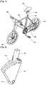
- FIG. 1 is a perspective view showing a bicycle having a saddle angle adjusting device, according to the first embodiment of the present invention
- FIG. 2 is a detailed perspective view showing the saddle angle adjusting device of FIG. 1 ;
- FIG. 3 is an exploded perspective view showing the saddle angle adjusting device of FIG. 1 ;
- FIG. 4 is a perspective view showing the state in which a coupling rod is moved from the position of FIG. 2 to change the angle of a saddle;
- FIG. 5 is a view showing the state in which a saddle coupling post is moved from the position of FIG. 2 , so that the angle of the saddle coupling post is changed;
- FIG. 6 is a side sectional view of FIG. 2 ;
- FIG. 7 is a rear view showing the saddle angle adjusting device of FIG. 1 ;
- FIG. 8 is a side sectional view of FIG. 4 ;
- FIG. 9 is a view showing the state in which the saddle of FIG. 1 is tilted backwards
- FIG. 10 is a view showing the state in which the saddle of FIG. 1 is tilted forwards
- FIG. 11 is a detailed perspective view showing an angle adjusting device for a bicycle saddle, according to the second embodiment of the present invention.
- FIG. 12 is a front sectional view showing the saddle angle adjusting device, according to the second embodiment of the present invention.
- FIG. 1 is a perspective view showing a bicycle having a saddle angle adjusting device, according to the first embodiment of the present invention.
- a saddle angle adjusting device 100 is installed between a saddle 700 and a height adjustment unit 800 of the bicycle, and functions to adjust the angle of the saddle 700 as desired.
- the bicycle includes wheels 200, pedals 300, a chain 400, a frame 500, handlebars 600, the saddle 700, and the height adjustment unit 800.
- the wheels 200 spin on the ground, thus moving the bicycle.
- the pedals 300 are pushed with a user's feet and thus rotated.
- the chain 400 transmits the rotation from the pedals 300 to the wheels 200.
- the pedals 300 and the chain 400 are mounted to the frame 500.
- the handlebars 600 are installed at the upper portion of the front of the frame 500, and are used for steering the bicycle.
- the saddle 700 is installed at the upper portion of the rear of the frame 500 to enable a user to sit thereon.
- the height adjustment unit 800 is provided between the frame 500 and the saddle 700, and functions to adjust the height of the saddle.
- the saddle angle adjusting device 100 includes a frame coupling block 110, a saddle coupling post 120, an angle adjusting unit 130, and an angle fixing unit 140.
- the frame coupling block 110 is coupled at the lower end thereof to the upper portion of the height adjustment unit 800.
- the saddle coupling post 120 is coupled to the upper end of the frame coupling block 110, and the angle fixing unit 140 is positioned outside the saddle coupling post 120 and is coupled to the upper end of the frame coupling block 110.
- the saddle coupling post 120 is coupled at the lower end thereof to the upper end of the frame coupling block 110, and is coupled at the upper end thereof to the saddle 700.
- a through hole is formed through the upper portion of the saddle coupling post 120, so that the angle adjusting unit 130 is coupled to the saddle coupling post 120 via the through hole.
- the saddle coupling post 120 may rotate forwards and backwards around the lower end thereof, which is coupled to the upper end of the frame coupling block 110.
- the angle adjusting unit 130 includes a coupling rod 131, one or more angle fixing rods 133, a link 135, an elastic member 137, and a stopper 139.
- the coupling rod 131 is inserted into the saddle coupling post 120.
- the angle fixing rods 133 are inserted into the angle fixing unit 140.
- the link 135 connects the coupling rod 131 to the angle fixing rods 133.
- the elastic member 137 is fitted over the coupling rod 131, so that the coupling rod 131 is in close contact with the saddle coupling post 120.
- the stopper 139 is mounted to one end of the coupling rod 131 in order to support the elastic member 137.
- the angle adjusting unit 130 is operated as follows.
- the coupling rod 131 inserted into the saddle coupling post 120 as shown in FIG. 2 , is pulled in the direction of the link 135, as shown in FIG. 4 , the angle fixing rods 133, which are connected to the link 135, are removed from the angle fixing unit 140.
- the saddle coupling post 120 may be moved forwards and backwards. In such a state, it is possible to adjust the angle of the saddle coupling post 120 as desired.
- the saddle coupling post 120 is set to a desired angle, and thereafter, force pulling the coupling rod 131 is eliminated, the coupling rod 131 is moved in the direction of the stopper 139 by the elastic force of the elastic member 137.
- the angle fixing rods 133 are inserted into the angle fixing unit 140, thus holding the saddle coupling post 120 at the adjusted angle.
- the coupling rod 131 is inserted into the through hole of the saddle coupling post 120.
- One end of the coupling rod 131 is coupled to the link 135, while the other end of the coupling rod 131 is coupled to the stopper 139.
- the elastic member 137 is positioned between the stopper 139 and the saddle coupling post 120 in such a way as to surround the coupling rod 131.
- Each angle fixing rod 133 is constructed so that one end of the angle fixing rod 133 is connected to the link 135, and the other end is inserted into the angle fixing unit 140. It is preferable that the angle fixing rod 133 comprise two angle fixing rods, as shown in FIG. 3 . However, the angle fixing rod 133 may be one, three or more in number.
- the link 135 may include a cross bar 135a, which connects the angle fixing rods 133 to each other, and a vertical bar 135b, which connects the cross bar 135a to the coupling rod 131.
- the link 135 may have a triangular configuration, which includes a cross bar for connecting the angle fixing rods 133 to each other, and diagonal bars for connecting the angle fixing rods 133 to the coupling rod 131. As long as the link 135 connects the coupling rod 131 to one end of each angle fixing rod 133, any shape of link is possible.
- the elastic member 137 is made of an elastic material, and comprises a spring, one end of which is in contact with the stopper 139, and the other end of which is in contact with the saddle coupling post 120.
- the spring surrounds the coupling rod 131.
- the stopper 139 is coupled to the end of the coupling rod 131, to which the link 135 is not coupled.
- the stopper 139 has a larger diameter than that of the elastic member 137, thus preventing the elastic member 137 from being removed from the coupling rod 131.
- the angle fixing unit 140 includes a pair of fan-shaped plates attached to the left and right sides of the frame coupling block 110, and a pair of rectangular plates respectively coupling front and rear edges of the fan-shaped plates to each other.
- One or more angle fixing holes 141 are formed along the arc of each fan-shaped plate, so that the angle fixing rods 133 can be inserted into the angle fixing holes 141.
- the angle fixing unit 140 is welded to the outer surface of the frame coupling block 110, thus preventing the angle fixing unit 140 from being moved forwards and backwards by the pressure of the saddle coupling post 120, to which the angle fixing unit 140 is coupled via the angle adjusting unit 130.
- the bicycle having the saddle angle adjusting device is operated as follows. That is, in the state in which the saddle coupling post 120 is rotated backwards, as shown in FIG. 9 , the angle adjusting unit 130 may be inserted into an associated angle fixing hole 141 in the angle fixing unit 140. By adjusting the angle of the saddle in this way, a rider can assume a natural posture even if his or her arms are long in proportion to the length of his or her legs, and even if he or she rides on a downhill road. Meanwhile, in the state in which the saddle coupling post 120 is rotated forwards, as shown in FIG. 10 , the angle adjusting unit 130 may be inserted into an associated angle fixing hole 141 in the angle fixing unit 140. By adjusting the angle of the saddle in this way, a rider can assume a natural posture even if his or her arms are short in proportion to the length of his or her legs, or even if he or she rides on an uphill road or runs at high speeds.
- FIG. 11 shows an angle adjusting device 100 for a bicycle saddle, according to the second embodiment of the present invention.
- the angle adjusting device 100 includes a frame coupling block 110, a saddle coupling post 120, an angle adjustment gear 160, a toothed angle fixing plate 150, and a gear holding screw 170.
- the angle adjustment gear 160 is a toothed wheel which has teeth of a predetermined size, and a hole the same size as the through hole of the saddle coupling post 120 is formed in the central portion of the toothed wheel.
- an angle adjustment knob 165 may protrude from the surface of the angle adjustment gear 160 that is opposite the surface of the angle adjustment gear 160 that is attached to the saddle coupling post 120.
- the angle adjustment knob 165 is used to rotate the angle adjustment gear 160.
- the toothed angle fixing plate 150 comprises a fan-shaped plate. Teeth are formed along the arc of the fan-shaped plate, and engage with the angle adjustment gear 160.
- the gear holding screw 170 passes through the hole which is formed in the central portion of the angle adjustment gear 160 and the through hole in the saddle coupling post 120, thus fastening the angle adjustment gear 160 to the saddle coupling post 120.
- the gear holding screw 170 is tightened, the angle adjustment gear 160 is in closer contact with the saddle coupling post 120, so that it is impossible to rotate the angle adjustment gear 160.
- the gear holding screw 170 is fastened to the saddle coupling post 120.
- the gear holding screw 170 may include a fastening bolt 176, a rotary nut 171, and wings 173.
- the fastening bolt 176 passes through the saddle coupling post 120, the angle adjustment gear 160, and the angle-adjusting knob 165.
- the rotary nut 171 is fitted onto the fastening bolt 176. As the rotary nut 171 rotates, the angle adjustment gear 160 and the angle-adjusting knob 165 come into close contact with the saddle coupling post 120.
- the wings 173 are used to rotate the rotary nut 171.
- the surface of the rotary nut 171 comes into close contact with the outer surface of the angle adjustment knob 165, so that the angle adjustment knob 165 is in close contact with the saddle coupling post 120. However, the upper and lower portions of the rotary nut 171 are not in contact with the angle adjustment knob 165. This construction prevents the angle adjustment knob 165 from rotating together with the rotary nut 171 when the rotary nut 171 rotates.
- the wings 173 are provided on the surface of the rotary nut 171, which is opposite the surface contacting the angle adjustment knob 165, and are formed to be long in a vertical or horizontal direction in order to easily transmit external rotating force to the rotary nut 171. As shown in FIG. 12 , the vertically or horizontally long portions are spaced apart from the rotary nut 171 by a predetermined interval, thus preventing the angle adjustment knob 165 from rotating together with the wings 173 when the wings 173 rotate. When the angle adjustment knob 165 is brought into close contact with the saddle coupling post 120 by the rotary nut 171, the long portions do not contact the knob 165.
- the saddle angle adjusting device 100 will be operated as follows. That is, when the gear holding screw 170 is loosened to make it possible to rotate the angle adjustment gear 160, the saddle coupling post 120 may move forwards and backwards. Thereby, it is possible to set the saddle coupling post 120 to a desired angle. When the gear holding screw 170 is tightened at the desired angle, the angle fixing gear 160 is held at that position. At this time, the teeth of the angle adjustment gear 160 engage with the teeth of the toothed angle fixing plate 150, thus holding the saddle coupling post 120 at the desired angle.
Landscapes
- Engineering & Computer Science (AREA)
- Mechanical Engineering (AREA)
- Steering Devices For Bicycles And Motorcycles (AREA)
- Automatic Cycles, And Cycles In General (AREA)
- Axle Suspensions And Sidecars For Cycles (AREA)
Claims (9)
- Dispositif de réglage d'angle de selle (100) pour une bicyclette comportant une unité de réglage de hauteur (800) entre un cadre (500) et une selle (700), le dispositif de réglage d'angle de selle (100) comprenant :un bloc d'accouplement de cadre (110) destiné à être accouplé par une extrémité inférieure de celui-ci à une partie supérieure de l'unité de réglage de hauteur (800) ; un tube d'accouplement de selle (120) accouplé à une extrémité inférieure de celui-ci à une extrémité supérieure du bloc d'accouplement de cadre (110) de telle manière que le tube d'accouplement de selle (120) tourne vers l'avant et vers l'arrière, et destiné à être accouplé à une extrémité supérieure du tube d'accouplement de selle à la selle (700), avec un trou traversant formé dans une partie supérieure du tube d'accouplement de selle (120) ; une unité de fixation d'angle (140) comprenant une paire de plaques en forme d'éventail attachées aux côtés gauche et droit du bloc d'accouplement de cadre, et une paire de plaques rectangulaires reliant respectivement les bords avant et arrière des plaques en forme d'évantail entre eux, avec une pluralité de trous (141) formés le long d'un arc de chacune des plaques en forme d'éventail ; et une unité de réglage d'angle (130) accouplée au tube d'accouplement de selle (120), une partie prédéterminée de l'unité de réglage d'angle (130) pouvant être détachée des trous (141) formés dans l'unité de fixation d'angle (140) pour commander la rotation du tube d'accouplement de selle (120) .
- Dispositif de réglage d'angle de selle selon la revendication 1, dans lequel l'unité de réglage d'angle (130) comprend : une tige d'accouplement (131) accouplée au tube d'accouplement de selle (120) ; une ou plusieurs tiges de fixation d'angle (133) insérée(s) dans l'unité de fixation d'angle (140) ; une liaison (135) pour connecter une extrémité de la tige d'accouplement (131) à une extrémité de chacune des tiges de fixation d'angle (133) de telle manière que la tige d'accouplement (131) est parallèle aux tiges de fixation d'angle (133) ; un élément élastique (137), qui est fait d'un matériau ayant une élasticité, et qui est monté sur la tige d'accouplement (131) ; et une butée (139) accouplée à une extrémité de la tige d'accouplement (131), qui n'est pas connectée à la liaison (135), et supportant l'élément élastique (137), dans lequel l'unité de réglage d'angle (130) est actionnée de telle manière que, quand la tige d'accouplement (131), accouplée au tube d'accouplement de selle (120), est déplacée dans une direction de la liaison (135) par une force extérieure de telle manière que les tiges de fixation d'angle (133) connectées à la liaison sont retirées de l'unité de fixation d'angle (130), le tube d'accouplement de selle (120) se déplace en avant et en arrière pour être réglé selon un angle souhaité, et, quand la force déplaçant la tige d'accouplement (131) est éliminée à un angle souhaité, la tige d'accouplement (131) est déplacée dans une direction de la butée (139) par la force élastique de l'élément élastique (137), et simultanément, les tiges de fixation d'angle (133) sont insérées dans l'unité de fixation d'angle (140), retenant ainsi le tube d'accouplement de selle (120) à l'angle souhaité.
- Dispositif de réglage d'angle de selle selon la revendication 2, dans lequel la tige d'accouplement (131) est insérée dans le trou traversant présent dans le tube d'accouplement de selle (120), une première extrémité de la tige d'accouplement étant accouplée à la liaison (135), et une deuxième extrémité de la tige d'accouplement étant accouplée à la butée (139), l'élément élastique (137) étant positionné entre la butée (139) et le tube d'accouplement de selle (120) de manière à entourer la tige d'accouplement (131).
- Dispositif de réglage d'angle de selle selon la revendication 2, dans lequel la liaison (135) comprend : une barre horizontale (135a) pour relier les tiges de fixation d'angle (133) entre elles ; et une barre verticale (135b) pour connecter la barre horizontale (135a) à la tige d'accouplement (131).
- Dispositif de réglage d'angle de selle (100) pour une bicyclette comportant une unité de réglage de hauteur (800) entre un cadre (500) et une selle (700), le dispositif de réglage d'angle de selle (100) comprenant :un bloc d'accouplement de cadre (110) destiné à être accouplé par une extrémité inférieure de celui-ci à une partie supérieure de l'unité de réglage de hauteur (800) ; un tube d'accouplement de selle (120) accouplé à une extrémité inférieure de celui-ci à une extrémité supérieure du bloc d'accouplement de cadre (110) de telle manière que le tube d'accouplement de selle (120) tourne vers l'avant et vers l'arrière, et destiné à être accouplé à une extrémité supérieure du tube d'accouplement de selle à la selle, avec un trou traversant formé dans une partie supérieure du tube d'accouplement de selle (120) ; une roue dentée de réglage d'angle (160) ayant une taille de dents prédéterminée, avec un trou formé dans une partie centrale de la roue dentée de réglage d'angle (160) et ayant la même taille que le trou traversant ; une plaque de fixation d'angle dentée (150) comprenant une plaque en forme d'éventail, avec une dent formée le long d'un arc de la plaque en forme d'éventail (150) destinée à se mettre en prise avec la roue dentée de réglage d'angle (160) ; et une vis de maintien de roue dentée (170) passant dans le trou formé dans la partie centrale de la roue dentée de réglage d'angle (160) et dans le trou traversant du tube d'accouplement de selle (120), et commandant la puissance d'accouplement entre la roue dentée de réglage d'angle (160) et le tube d'accouplement de selle (120), dans lequel la roue dentée de réglage d'angle (160) peut tourner et le tube d'accouplement de selle (120) peut être déplacé en avant et en arrière en desserrant la vis de maintien de roue dentée (170) pour réduire la puissance d'accouplement de celle-ci, de sorte qu'un angle du tube d'accouplement de selle (120) peut être réglé comme souhaité, et la dent de la roue dentée de réglage d'angle (160) se met en prise avec la dent de la plaque de fixation d'angle dentée (150) en serrant la vis de maintien de roue dentée (170) pour augmenter la puissance d'accouplement de celle-ci, de sorte que le tube d'accouplement de selle (120) est réglé sur un angle souhaité.
- Dispositif de réglage d'angle de selle selon la revendication 5, dans lequel un bouton de réglage d'angle (165) fait saillie depuis une surface de la roue dentée de réglage d'angle (160) qui est opposée à une surface de la roue dentée de réglage d'angle accouplée au tube d'accouplement de selle (120).
- Dispositif de réglage d'angle de selle selon la revendication 6, dans lequel la vis de maintien de roue dentée (170) comprend : un boulon de fixation (176) fixé au tube d'accouplement de selle (120), et passant à travers le tube d'accouplement de selle (120), la roue dentée de réglage d'angle (160) et le bouton de réglage d'angle (165) ; un écrou rotatif (171) monté sur le boulon de fixation (176) et tournant de telle manière que la roue dentée de réglage d'angle (160) et le bouton de réglage d'angle (165) viennent en contact étroit avec le tube d'accouplement de selle (120) ; et une oreille (173) pour faire tourner l'écrou rotatif (171).
- Dispositif de réglage d'angle de selle selon la revendication 7, dans lequel une surface de l'écrou rotatif (171) est en contact étroit avec une surface extérieure du bouton de réglage d'angle (165), mais les extrémités supérieure et inférieure de l'écrou rotatif (171) ne sont pas en contact avec le bouton de réglage d'angle (165).
- Dispositif de réglage d'angle de selle selon la revendication 7, dans lequel l'oreille (173) est accouplée à une surface de l'écrou rotatif (171), qui n'entre pas en contact avec le bouton de réglage d'angle (165), et qui est longue dans une direction verticale et dans une direction horizontale.
Applications Claiming Priority (2)
| Application Number | Priority Date | Filing Date | Title |
|---|---|---|---|
| KR1020070104122A KR100908670B1 (ko) | 2007-10-16 | 2007-10-16 | 자전거 안장 각도조절 장치 |
| PCT/KR2007/006896 WO2009051292A1 (fr) | 2007-10-16 | 2007-12-27 | Dispositif de réglage d'angle pour selle de bicyclette |
Publications (3)
| Publication Number | Publication Date |
|---|---|
| EP2197732A1 EP2197732A1 (fr) | 2010-06-23 |
| EP2197732A4 EP2197732A4 (fr) | 2011-04-06 |
| EP2197732B1 true EP2197732B1 (fr) | 2012-05-02 |
Family
ID=40567537
Family Applications (1)
| Application Number | Title | Priority Date | Filing Date |
|---|---|---|---|
| EP07851808A Not-in-force EP2197732B1 (fr) | 2007-10-16 | 2007-12-27 | Dispositif de réglage d'angle pour selle de bicyclette |
Country Status (8)
| Country | Link |
|---|---|
| US (2) | US8424963B2 (fr) |
| EP (1) | EP2197732B1 (fr) |
| JP (1) | JP5143907B2 (fr) |
| KR (1) | KR100908670B1 (fr) |
| CN (1) | CN101815644B (fr) |
| AT (1) | ATE555973T1 (fr) |
| ES (1) | ES2387445T3 (fr) |
| WO (1) | WO2009051292A1 (fr) |
Families Citing this family (34)
| Publication number | Priority date | Publication date | Assignee | Title |
|---|---|---|---|---|
| US20100038498A1 (en) * | 2008-08-18 | 2010-02-18 | Skedco, Inc. | Configurable anchor point and modular kit for an anchor point |
| US8104987B2 (en) * | 2009-06-25 | 2012-01-31 | Johnson Health Tech Co. Ltd. | Self-locating engagement pin locking and unlocking apparatus |
| US8485597B2 (en) * | 2010-02-16 | 2013-07-16 | Chun Choo Kim | Angle adjustment device for bicycle saddle |
| KR101157840B1 (ko) * | 2010-02-18 | 2012-06-22 | 박훈근 | 팔운동을 병행하는 헬스 자전거 |
| KR100981994B1 (ko) * | 2010-03-31 | 2010-09-13 | 이영자 | 자전거에 탑승한 상태에서 안장 유지 각도를 조정할 수 있는 자전거용 안장 |
| KR101027158B1 (ko) * | 2010-10-11 | 2011-04-05 | 이영자 | 자전거용 안장의 유지각도 조정장치 |
| US8668257B2 (en) * | 2011-06-24 | 2014-03-11 | Yao-Chuan Wu | Foldable bracket of a chair |
| ES2405940B1 (es) * | 2011-11-30 | 2014-09-02 | José Luis FERNANDEZ SANCHEZ | Dispositivo de posicionamiento del sillín de una bicicleta |
| KR101167029B1 (ko) * | 2012-03-27 | 2012-07-24 | 김춘추 | 이동식 안장을 구비하는 자전거 |
| TWM446744U (zh) * | 2012-08-09 | 2013-02-11 | Chiu-Hsiang Lo | 自行車之車架 |
| KR101364771B1 (ko) * | 2012-10-08 | 2014-02-27 | 주식회사 유진로봇 | 유아용 세발 자전거 |
| US20140292020A1 (en) * | 2013-04-02 | 2014-10-02 | Joseph Gallo | Retractable Canopy Apparatus For a Golf Cart |
| CN104210577A (zh) * | 2013-05-30 | 2014-12-17 | 上海黄燕模塑工程有限公司 | 车座单元及其自行车 |
| US9481420B2 (en) * | 2013-08-01 | 2016-11-01 | Specialized Bicycle Components, Inc. | Saddle adjustment system |
| US9839292B2 (en) * | 2014-04-08 | 2017-12-12 | John Hart Miller | Rotating and non-rotating reclining chairs w/tilting mechanisms |
| KR101483948B1 (ko) * | 2014-11-12 | 2015-01-20 | 이경현 | 고관절 일치형 가상축형 안장 |
| AU2015364633A1 (en) * | 2014-12-18 | 2017-08-10 | Specialized Bicycle Components, Inc. | Saddle adjustment system |
| US9616954B2 (en) | 2014-12-18 | 2017-04-11 | Specialized Bicycle Components, Inc. | Saddle adjustment system |
| CN104627274A (zh) * | 2015-01-23 | 2015-05-20 | 天津市禧畅自行车有限公司 | 新型自行车鞍座装置 |
| CN104709386A (zh) * | 2015-01-23 | 2015-06-17 | 天津都市玛自行车有限公司 | 一种新型自行车车座结构 |
| KR101635719B1 (ko) * | 2015-07-21 | 2016-07-01 | 황성만 | 자전거의 안장 경사각 조절장치 |
| KR101727395B1 (ko) * | 2015-08-31 | 2017-04-14 | 이동철 | 자전거용 안장구조체 |
| US10021979B2 (en) | 2016-02-22 | 2018-07-17 | John Hart Miller | Rotating and non-rotating reclining chairs with tilting mechanisms |
| KR101908847B1 (ko) * | 2017-03-24 | 2018-10-16 | 황성만 | 전동식 안장각도 조절장치 |
| CN107031759B (zh) * | 2017-06-01 | 2022-09-02 | 丁存保 | 电动自行车儿童前置可拆卸座椅 |
| US11510401B2 (en) * | 2017-12-09 | 2022-11-29 | Rod Dawg Holding LLC | Rod holding device and methods of use |
| US20190174734A1 (en) * | 2017-12-09 | 2019-06-13 | Rod Dawg Holdings Llc | Rod holding device and methods of use |
| CN110001828B (zh) * | 2019-04-29 | 2024-07-02 | 深圳市昌达顺科技有限公司 | 一种可调节车座及折叠车 |
| US20200344987A1 (en) * | 2019-05-03 | 2020-11-05 | Winthrop Tackle | Adjustable butt and reel seat for a fishing rod |
| CA3177721C (fr) | 2020-05-04 | 2024-11-05 | David Watson | Dispositif pour le reglage d'une position de siege d'un siege de bicyclette |
| CN111713187B (zh) * | 2020-06-12 | 2022-12-13 | 江苏大学 | 一种葡萄藤多刮板清土装置及安装该装置的工程机械 |
| JP6793276B1 (ja) * | 2020-06-29 | 2020-12-02 | 芳徳 川崎 | 自転車型ライン引き装置 |
| US12448072B2 (en) | 2020-12-22 | 2025-10-21 | Noel Dolotallas | Multi-position and orientation saddle attachment device |
| KR200498058Y1 (ko) * | 2021-10-18 | 2024-06-11 | 현민주 | 자전거 건강 안장 |
Family Cites Families (26)
| Publication number | Priority date | Publication date | Assignee | Title |
|---|---|---|---|---|
| US453237A (en) * | 1891-06-02 | Invalid-bed | ||
| AT296532B (de) * | 1970-10-30 | 1972-02-25 | Wiesner Hager Kg | Vorrichtung zur Neigungsverstellung der Rückenlehne von Sesseln, insbesondere von Bürosesseln |
| DE2747584A1 (de) * | 1977-10-24 | 1979-04-26 | Keiper Automobiltechnik Gmbh | Traegheitssperreinrichtung fuer kraftfahrzeugsitze |
| JPS604476A (ja) | 1983-06-22 | 1985-01-10 | 株式会社加島サドル製作所 | 角度調節型サドル |
| US4772069A (en) | 1987-12-24 | 1988-09-20 | Schwinn Bicycle Company | Longitudinally adjustable saddle mounting for cycle-type apparatus |
| CA2011328C (fr) * | 1990-03-02 | 1995-08-22 | Marc Bernier | Support incline vers le bas pour montage d'une antenne sur une tour metallique |
| US5163735A (en) * | 1991-07-15 | 1992-11-17 | Ford Motor Company | Reduced pre-lock travel seat back hinge inertia lock |
| US5244301A (en) | 1992-09-22 | 1993-09-14 | Kurke Martin I | Bicycle seat mount |
| US5265969A (en) * | 1992-12-16 | 1993-11-30 | Chuang Ching Pao | Angle-adjustable joint |
| US5364160A (en) * | 1993-02-26 | 1994-11-15 | Fritschen Thomas M | Open air duct bicycle saddle mount |
| US5988741A (en) | 1995-04-17 | 1999-11-23 | Voss; Darrell W. | Bicycle seat post flare post |
| US5779249A (en) * | 1996-09-03 | 1998-07-14 | Lin; Gin-Ding | Seat height adjusting means of a bicycle |
| US5727583A (en) * | 1997-03-19 | 1998-03-17 | Kennedy; Phillip Donald | Service umbrella |
| JPH11347171A (ja) * | 1998-06-04 | 1999-12-21 | Satoru Nakayama | ゴルフのスイング練習装置 |
| FR2790438A1 (fr) | 1999-03-05 | 2000-09-08 | Gilles Reguillon | Dispositif de reglage d'une selle de bicyclette |
| US6176459B1 (en) * | 1999-03-29 | 2001-01-23 | Attwood Corporation | Self-locking angularly-tilting seat support |
| US6533237B1 (en) * | 2000-02-08 | 2003-03-18 | Third Arm Solutions, Inc. | Apparatus and method for holding an elongated member |
| DE10126757C1 (de) | 2001-06-01 | 2002-12-12 | Franz Freund | Vorrichtung für ein Fahrrad zur individuellen Anpassung des Sitzwinkels und der Sattelneigungseinstellung an einen Nutzer bzw. einer Nutzerin und zur aktuellen Bedarfsanpassung innerhalb einer vorgegebenen Verstelldistanz |
| EP1535540A4 (fr) * | 2002-07-05 | 2006-06-07 | Ts Tech Co Ltd | Dispositif d'inclinaison de siege automobile |
| JP4283591B2 (ja) * | 2003-04-30 | 2009-06-24 | 株式会社マルイ | 自転車用サドルの取付構造 |
| TW581028U (en) | 2003-04-30 | 2004-03-21 | Selle Tech Ind Co Ltd | Bicycle seat capable of adjusting inclined angle |
| US6899389B2 (en) | 2003-09-03 | 2005-05-31 | Macneil Bikes, Inc. | Bicycle seat assembly |
| DE102005038565A1 (de) * | 2005-08-12 | 2007-02-15 | Udo Ochendalski | Vorrichtung zur Winkeleinstellung eines Neigungswinkels eines Sattels |
| KR20080045209A (ko) * | 2005-09-15 | 2008-05-22 | 인티어 오토모티브 시팅 시스템스 게엠베하 | 시트 쿠션 로커 기구를 갖는 시트 조립체 |
| CN2839075Y (zh) * | 2005-09-23 | 2006-11-22 | 张权伟 | 可调式旋转形自行车座架 |
| JP4084400B2 (ja) * | 2006-06-02 | 2008-04-30 | 有限会社藤原ホイル | 自転車のサドル昇降装置 |
-
2007
- 2007-10-16 KR KR1020070104122A patent/KR100908670B1/ko not_active Expired - Fee Related
- 2007-12-27 ES ES07851808T patent/ES2387445T3/es active Active
- 2007-12-27 EP EP07851808A patent/EP2197732B1/fr not_active Not-in-force
- 2007-12-27 WO PCT/KR2007/006896 patent/WO2009051292A1/fr not_active Ceased
- 2007-12-27 CN CN2007801006323A patent/CN101815644B/zh not_active Expired - Fee Related
- 2007-12-27 US US12/679,480 patent/US8424963B2/en not_active Expired - Fee Related
- 2007-12-27 AT AT07851808T patent/ATE555973T1/de active
- 2007-12-27 JP JP2010529838A patent/JP5143907B2/ja not_active Expired - Fee Related
-
2012
- 2012-04-03 US US13/438,272 patent/US9193406B2/en not_active Expired - Fee Related
Also Published As
| Publication number | Publication date |
|---|---|
| EP2197732A1 (fr) | 2010-06-23 |
| CN101815644A (zh) | 2010-08-25 |
| KR100908670B1 (ko) | 2009-07-21 |
| CN101815644B (zh) | 2012-11-21 |
| JP2011500420A (ja) | 2011-01-06 |
| JP5143907B2 (ja) | 2013-02-13 |
| WO2009051292A1 (fr) | 2009-04-23 |
| KR20090038688A (ko) | 2009-04-21 |
| US20130093223A1 (en) | 2013-04-18 |
| US9193406B2 (en) | 2015-11-24 |
| ES2387445T3 (es) | 2012-09-24 |
| US20100194156A1 (en) | 2010-08-05 |
| ATE555973T1 (de) | 2012-05-15 |
| US8424963B2 (en) | 2013-04-23 |
| EP2197732A4 (fr) | 2011-04-06 |
Similar Documents
| Publication | Publication Date | Title |
|---|---|---|
| EP2197732B1 (fr) | Dispositif de réglage d'angle pour selle de bicyclette | |
| US6648353B1 (en) | Upright step-cycle with elliptical motion pedalling | |
| AU2012200089B2 (en) | Infant scooter | |
| CN102292257B (zh) | 自行车车座角度调整装置 | |
| CN104520176B (zh) | 自行车 | |
| US7762569B2 (en) | Cycle having unique balancing capabilities | |
| US5791675A (en) | Bicycle training device | |
| CN103910010A (zh) | 可调整式自行车车架结构 | |
| US6247714B1 (en) | Recumbent cycle with improved suspension | |
| KR100967167B1 (ko) | 자전거 안장 각도조절 장치 | |
| US5297846A (en) | Pivoting bicycle seat assembly | |
| US20030168829A1 (en) | Bicycle safety training handle | |
| KR102174690B1 (ko) | 3개의 구동부를 구비하고 조향과 동시에 자연각에 의한 틸팅기능을 구사하는 역삼륜 자전거 | |
| KR101846446B1 (ko) | 좌식 및 입식 겸용 헬스용 자전거 | |
| US10112679B2 (en) | Bicycle with support device | |
| WO2016071526A1 (fr) | Bicyclette de loisir | |
| RU194429U1 (ru) | Трехколесный терапевтический электровелосипед для людей с ограниченными возможностями | |
| KR100483061B1 (ko) | 롤러보드 | |
| KR200183326Y1 (ko) | 경사가변식 등받이와 높이조절식 핸들을 장착한 자전거 | |
| RU194955U1 (ru) | Трехколесный терапевтический электробеговел для людей с ограниченными возможностями | |
| KR20200001273A (ko) | 자전거용 어깨 받침대 | |
| CN209776699U (zh) | 一种带有伸缩托架的自行车车把 | |
| KR200301206Y1 (ko) | 롤러보드 | |
| US8668260B2 (en) | Bicycle seat assembly | |
| US20180065697A1 (en) | Pedal driven standing stype bicycle |
Legal Events
| Date | Code | Title | Description |
|---|---|---|---|
| PUAI | Public reference made under article 153(3) epc to a published international application that has entered the european phase |
Free format text: ORIGINAL CODE: 0009012 |
|
| 17P | Request for examination filed |
Effective date: 20100305 |
|
| AK | Designated contracting states |
Kind code of ref document: A1 Designated state(s): AT BE BG CH CY CZ DE DK EE ES FI FR GB GR HU IE IS IT LI LT LU LV MC MT NL PL PT RO SE SI SK TR |
|
| AX | Request for extension of the european patent |
Extension state: AL BA HR MK RS |
|
| DAX | Request for extension of the european patent (deleted) | ||
| A4 | Supplementary search report drawn up and despatched |
Effective date: 20110303 |
|
| GRAP | Despatch of communication of intention to grant a patent |
Free format text: ORIGINAL CODE: EPIDOSNIGR1 |
|
| GRAS | Grant fee paid |
Free format text: ORIGINAL CODE: EPIDOSNIGR3 |
|
| GRAA | (expected) grant |
Free format text: ORIGINAL CODE: 0009210 |
|
| AK | Designated contracting states |
Kind code of ref document: B1 Designated state(s): AT BE BG CH CY CZ DE DK EE ES FI FR GB GR HU IE IS IT LI LT LU LV MC MT NL PL PT RO SE SI SK TR |
|
| REG | Reference to a national code |
Ref country code: GB Ref legal event code: FG4D |
|
| REG | Reference to a national code |
Ref country code: AT Ref legal event code: REF Ref document number: 555973 Country of ref document: AT Kind code of ref document: T Effective date: 20120515 Ref country code: CH Ref legal event code: EP |
|
| REG | Reference to a national code |
Ref country code: IE Ref legal event code: FG4D |
|
| REG | Reference to a national code |
Ref country code: DE Ref legal event code: R096 Ref document number: 602007022509 Country of ref document: DE Effective date: 20120705 |
|
| REG | Reference to a national code |
Ref country code: NL Ref legal event code: T3 |
|
| REG | Reference to a national code |
Ref country code: ES Ref legal event code: FG2A Ref document number: 2387445 Country of ref document: ES Kind code of ref document: T3 Effective date: 20120924 |
|
| REG | Reference to a national code |
Ref country code: LT Ref legal event code: MG4D Effective date: 20120502 |
|
| PG25 | Lapsed in a contracting state [announced via postgrant information from national office to epo] |
Ref country code: CY Free format text: LAPSE BECAUSE OF FAILURE TO SUBMIT A TRANSLATION OF THE DESCRIPTION OR TO PAY THE FEE WITHIN THE PRESCRIBED TIME-LIMIT Effective date: 20120502 Ref country code: FI Free format text: LAPSE BECAUSE OF FAILURE TO SUBMIT A TRANSLATION OF THE DESCRIPTION OR TO PAY THE FEE WITHIN THE PRESCRIBED TIME-LIMIT Effective date: 20120502 Ref country code: SE Free format text: LAPSE BECAUSE OF FAILURE TO SUBMIT A TRANSLATION OF THE DESCRIPTION OR TO PAY THE FEE WITHIN THE PRESCRIBED TIME-LIMIT Effective date: 20120502 Ref country code: LT Free format text: LAPSE BECAUSE OF FAILURE TO SUBMIT A TRANSLATION OF THE DESCRIPTION OR TO PAY THE FEE WITHIN THE PRESCRIBED TIME-LIMIT Effective date: 20120502 Ref country code: IS Free format text: LAPSE BECAUSE OF FAILURE TO SUBMIT A TRANSLATION OF THE DESCRIPTION OR TO PAY THE FEE WITHIN THE PRESCRIBED TIME-LIMIT Effective date: 20120902 Ref country code: PL Free format text: LAPSE BECAUSE OF FAILURE TO SUBMIT A TRANSLATION OF THE DESCRIPTION OR TO PAY THE FEE WITHIN THE PRESCRIBED TIME-LIMIT Effective date: 20120502 |
|
| REG | Reference to a national code |
Ref country code: AT Ref legal event code: MK05 Ref document number: 555973 Country of ref document: AT Kind code of ref document: T Effective date: 20120502 |
|
| PG25 | Lapsed in a contracting state [announced via postgrant information from national office to epo] |
Ref country code: PT Free format text: LAPSE BECAUSE OF FAILURE TO SUBMIT A TRANSLATION OF THE DESCRIPTION OR TO PAY THE FEE WITHIN THE PRESCRIBED TIME-LIMIT Effective date: 20120903 Ref country code: SI Free format text: LAPSE BECAUSE OF FAILURE TO SUBMIT A TRANSLATION OF THE DESCRIPTION OR TO PAY THE FEE WITHIN THE PRESCRIBED TIME-LIMIT Effective date: 20120502 Ref country code: LV Free format text: LAPSE BECAUSE OF FAILURE TO SUBMIT A TRANSLATION OF THE DESCRIPTION OR TO PAY THE FEE WITHIN THE PRESCRIBED TIME-LIMIT Effective date: 20120502 Ref country code: GR Free format text: LAPSE BECAUSE OF FAILURE TO SUBMIT A TRANSLATION OF THE DESCRIPTION OR TO PAY THE FEE WITHIN THE PRESCRIBED TIME-LIMIT Effective date: 20120803 |
|
| PG25 | Lapsed in a contracting state [announced via postgrant information from national office to epo] |
Ref country code: BE Free format text: LAPSE BECAUSE OF FAILURE TO SUBMIT A TRANSLATION OF THE DESCRIPTION OR TO PAY THE FEE WITHIN THE PRESCRIBED TIME-LIMIT Effective date: 20120502 |
|
| PG25 | Lapsed in a contracting state [announced via postgrant information from national office to epo] |
Ref country code: RO Free format text: LAPSE BECAUSE OF FAILURE TO SUBMIT A TRANSLATION OF THE DESCRIPTION OR TO PAY THE FEE WITHIN THE PRESCRIBED TIME-LIMIT Effective date: 20120502 Ref country code: DK Free format text: LAPSE BECAUSE OF FAILURE TO SUBMIT A TRANSLATION OF THE DESCRIPTION OR TO PAY THE FEE WITHIN THE PRESCRIBED TIME-LIMIT Effective date: 20120502 Ref country code: CZ Free format text: LAPSE BECAUSE OF FAILURE TO SUBMIT A TRANSLATION OF THE DESCRIPTION OR TO PAY THE FEE WITHIN THE PRESCRIBED TIME-LIMIT Effective date: 20120502 Ref country code: EE Free format text: LAPSE BECAUSE OF FAILURE TO SUBMIT A TRANSLATION OF THE DESCRIPTION OR TO PAY THE FEE WITHIN THE PRESCRIBED TIME-LIMIT Effective date: 20120502 Ref country code: AT Free format text: LAPSE BECAUSE OF FAILURE TO SUBMIT A TRANSLATION OF THE DESCRIPTION OR TO PAY THE FEE WITHIN THE PRESCRIBED TIME-LIMIT Effective date: 20120502 Ref country code: SK Free format text: LAPSE BECAUSE OF FAILURE TO SUBMIT A TRANSLATION OF THE DESCRIPTION OR TO PAY THE FEE WITHIN THE PRESCRIBED TIME-LIMIT Effective date: 20120502 |
|
| PGFP | Annual fee paid to national office [announced via postgrant information from national office to epo] |
Ref country code: IT Payment date: 20121214 Year of fee payment: 6 Ref country code: GB Payment date: 20121220 Year of fee payment: 6 Ref country code: ES Payment date: 20121120 Year of fee payment: 6 |
|
| PLBE | No opposition filed within time limit |
Free format text: ORIGINAL CODE: 0009261 |
|
| STAA | Information on the status of an ep patent application or granted ep patent |
Free format text: STATUS: NO OPPOSITION FILED WITHIN TIME LIMIT |
|
| 26N | No opposition filed |
Effective date: 20130205 |
|
| PGFP | Annual fee paid to national office [announced via postgrant information from national office to epo] |
Ref country code: DE Payment date: 20130228 Year of fee payment: 6 Ref country code: FR Payment date: 20130123 Year of fee payment: 6 |
|
| REG | Reference to a national code |
Ref country code: DE Ref legal event code: R097 Ref document number: 602007022509 Country of ref document: DE Effective date: 20130205 |
|
| PGFP | Annual fee paid to national office [announced via postgrant information from national office to epo] |
Ref country code: NL Payment date: 20121219 Year of fee payment: 6 |
|
| PG25 | Lapsed in a contracting state [announced via postgrant information from national office to epo] |
Ref country code: MC Free format text: LAPSE BECAUSE OF NON-PAYMENT OF DUE FEES Effective date: 20121231 Ref country code: BG Free format text: LAPSE BECAUSE OF FAILURE TO SUBMIT A TRANSLATION OF THE DESCRIPTION OR TO PAY THE FEE WITHIN THE PRESCRIBED TIME-LIMIT Effective date: 20120802 |
|
| REG | Reference to a national code |
Ref country code: CH Ref legal event code: PL |
|
| REG | Reference to a national code |
Ref country code: IE Ref legal event code: MM4A |
|
| PG25 | Lapsed in a contracting state [announced via postgrant information from national office to epo] |
Ref country code: LI Free format text: LAPSE BECAUSE OF NON-PAYMENT OF DUE FEES Effective date: 20121231 Ref country code: IE Free format text: LAPSE BECAUSE OF NON-PAYMENT OF DUE FEES Effective date: 20121227 Ref country code: CH Free format text: LAPSE BECAUSE OF NON-PAYMENT OF DUE FEES Effective date: 20121231 |
|
| PG25 | Lapsed in a contracting state [announced via postgrant information from national office to epo] |
Ref country code: MT Free format text: LAPSE BECAUSE OF FAILURE TO SUBMIT A TRANSLATION OF THE DESCRIPTION OR TO PAY THE FEE WITHIN THE PRESCRIBED TIME-LIMIT Effective date: 20120502 |
|
| PG25 | Lapsed in a contracting state [announced via postgrant information from national office to epo] |
Ref country code: TR Free format text: LAPSE BECAUSE OF FAILURE TO SUBMIT A TRANSLATION OF THE DESCRIPTION OR TO PAY THE FEE WITHIN THE PRESCRIBED TIME-LIMIT Effective date: 20120502 |
|
| PG25 | Lapsed in a contracting state [announced via postgrant information from national office to epo] |
Ref country code: LU Free format text: LAPSE BECAUSE OF NON-PAYMENT OF DUE FEES Effective date: 20121227 |
|
| REG | Reference to a national code |
Ref country code: DE Ref legal event code: R119 Ref document number: 602007022509 Country of ref document: DE |
|
| REG | Reference to a national code |
Ref country code: NL Ref legal event code: V1 Effective date: 20140701 |
|
| PG25 | Lapsed in a contracting state [announced via postgrant information from national office to epo] |
Ref country code: HU Free format text: LAPSE BECAUSE OF FAILURE TO SUBMIT A TRANSLATION OF THE DESCRIPTION OR TO PAY THE FEE WITHIN THE PRESCRIBED TIME-LIMIT Effective date: 20071227 |
|
| GBPC | Gb: european patent ceased through non-payment of renewal fee |
Effective date: 20131227 |
|
| REG | Reference to a national code |
Ref country code: FR Ref legal event code: ST Effective date: 20140829 |
|
| REG | Reference to a national code |
Ref country code: DE Ref legal event code: R119 Ref document number: 602007022509 Country of ref document: DE Effective date: 20140701 |
|
| PG25 | Lapsed in a contracting state [announced via postgrant information from national office to epo] |
Ref country code: NL Free format text: LAPSE BECAUSE OF NON-PAYMENT OF DUE FEES Effective date: 20140701 Ref country code: DE Free format text: LAPSE BECAUSE OF NON-PAYMENT OF DUE FEES Effective date: 20140701 |
|
| PG25 | Lapsed in a contracting state [announced via postgrant information from national office to epo] |
Ref country code: FR Free format text: LAPSE BECAUSE OF NON-PAYMENT OF DUE FEES Effective date: 20131231 Ref country code: GB Free format text: LAPSE BECAUSE OF NON-PAYMENT OF DUE FEES Effective date: 20131227 |
|
| REG | Reference to a national code |
Ref country code: ES Ref legal event code: FD2A Effective date: 20150708 |
|
| PG25 | Lapsed in a contracting state [announced via postgrant information from national office to epo] |
Ref country code: ES Free format text: LAPSE BECAUSE OF NON-PAYMENT OF DUE FEES Effective date: 20131228 |
|
| PG25 | Lapsed in a contracting state [announced via postgrant information from national office to epo] |
Ref country code: IT Free format text: LAPSE BECAUSE OF NON-PAYMENT OF DUE FEES Effective date: 20131231 |
|
| PG25 | Lapsed in a contracting state [announced via postgrant information from national office to epo] |
Ref country code: IT Free format text: LAPSE BECAUSE OF NON-PAYMENT OF DUE FEES Effective date: 20131227 |