EP2197734B1 - Bewegbarer ballast für ein segelboot und schiff - Google Patents
Bewegbarer ballast für ein segelboot und schiff Download PDFInfo
- Publication number
- EP2197734B1 EP2197734B1 EP07803086A EP07803086A EP2197734B1 EP 2197734 B1 EP2197734 B1 EP 2197734B1 EP 07803086 A EP07803086 A EP 07803086A EP 07803086 A EP07803086 A EP 07803086A EP 2197734 B1 EP2197734 B1 EP 2197734B1
- Authority
- EP
- European Patent Office
- Prior art keywords
- tunnel
- conduit
- ballast
- sailboat
- movable
- Prior art date
- Legal status (The legal status is an assumption and is not a legal conclusion. Google has not performed a legal analysis and makes no representation as to the accuracy of the status listed.)
- Active
Links
Images
Classifications
-
- B—PERFORMING OPERATIONS; TRANSPORTING
- B63—SHIPS OR OTHER WATERBORNE VESSELS; RELATED EQUIPMENT
- B63B—SHIPS OR OTHER WATERBORNE VESSELS; EQUIPMENT FOR SHIPPING
- B63B39/00—Equipment to decrease pitch, roll, or like unwanted vessel movements; Apparatus for indicating vessel attitude
- B63B39/02—Equipment to decrease pitch, roll, or like unwanted vessel movements; Apparatus for indicating vessel attitude to decrease vessel movements by displacement of masses
Definitions
- This invention relates to sailboats and partially to motorboats. More specifically, this invention describes equipment intended to improve the performance of a sailboat by increasing the stability, or "stiffness", - the ability of the sailboat to resist the heeling force of the sails.
- the stiffness as it will be called in the following, is afforded by the righting moment. Enhancing the stiffness brings significant extra power to the sails and, furthermore, increases the equilibrium and the safety of boats in general. Good stiffness enables a ship to have all sails set wind abeam, whilst maintaining the boat at angles of about a normal heeling (the first 30 degrees of heeling). The greater the stiffness (or righting ability) of the boat, the more powerful the sails can be and the faster the boat can be.
- Sailboats must have a system ensuring stability to counterbalance the sails' thrust.
- this problem is solved in various ways in sailboats: multihulls have several hulls, big centreboard boats have inside or outside ballasts, keelboats have an outside fixed ballast also called fin keel. Some race keelboats have one or two movable keels. In addition all these sailboats can have several inside ballast tanks.
- ballasted swinging keel brought a beginning of response to this problem, allowing to anticipate the heeling by pre inclining the keel which increases the stiffness. But the anti-leeway plane, once tilted, is transformed into a foil and develops a undesired lift effect.
- the double ballasted swinging keel system allows to partially solve this problem by presetting the incidence angles.
- the hinge axes are rotated slightly one towards the other in order to cancel out the lift effect.
- WO 91/19641 and FR 2818236 relate to systems which are based on movable ballasts inside a hull.
- FR 2818236 offer several disadvantages.
- the solution proposed in FR 2818236 can hardly be applied on a cruising sailboat because it occupies the complete space on the boat's centre and thus bans all crew movement in the hull.
- the weight is positioned high in the hull and this is detrimental to righting the boat, once capsised.
- the mast must swing athwart ship to actuate the ballast which weakens the whole system. Indirectly resulting therefrom, good watertightness is almost impossible, which is a big disadvantage. Tilting the mast and the sails intentionally to actuate the system is simply aberrant since it is deteriorating the above problem of the sails thrust force acting overboard which is generating the prejudicing loading vector on the fore part of the boat.
- WO 01/47769 A discloses a movable ballast system for a ship, in which ballast spheres inside a conduit are put into motion through smaller spheres. The smaller spheres are put into motion using mechanical or electrical means. The disclosure does not foresee means to avoid oxidation of the mechanical or electrical means.
- the tunnel or conduit may comprise sidewalls provided with a set of rails or tracks for the movable ballast.
- the movable ballast may be provided as a train set.
- the operation of the movable ballast in the tunnel or conduit may be manual.
- the operation of the movable ballast in the tunnel or conduit may be power-assisted.
- a mechanical force may be applied to the movable ballast.
- the hermetically sealed tunnel or conduit may comprise a neutral atmosphere, preferably nitrogen.
- the tunnel may be built like a cylinder and the ballast like a two-headed piston.
- the ballast may be actuated by pressurising a gas or a liquid on one of its faces and releasing the gas or the liquid on its other face.
- the piston has an articulated body allowing it to bend between its two ends.
- the position of the movable ballast in the tunnel or conduit system may be controlled by a computerized means equipped with I/O ports e.g. a PLC
- the computerized means may use one or move of the information of the heeling measure, the wind direction or the rudder position to monitor the position of the movable ballast.
- Embodiments of the present invention may allow to increase on request and quickly, the stiffness of sailboats. Moreover, the present invention may also allow to control the heeling in order to improve comfort.
- the stiffness and comfort of a sailboat may be improved considerably by means of a movable ballast moving in a tunnel or conduit built inside and close to the hull.
- a set of rails or tracks may be fitted around the tunnel sides, which allows the ballast to move accurately when the boat is sailing in a rough sea.
- the ballast may be made of a high-density material, such as lead. This allows the tunnel to be compact and it may be located under the floor and in principle may be hidden by the accommodations.
- the stiffness may be increased by moving the ballast windward to balance a part of the heel. If so designed, the trim angle may also be corrected on the same principle.
- the operation may be performed manually or automatically by computerized means like a PLC. In some configurations this system may be adapted to meet explosion-proof specifications.
- a movable ballast arrangement for a vessel is located in a tunnel or conduit provided inside and preferably close to the bottom hull of the vessel.
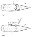
- the movable ballast 11a to 11e is located in a tunnel or a conduit 12.
- the tunnel or conduit 12 may advantageously be composed of straight and/or a curved sections.
- a preferred shape of the tunnel or conduit 12 is a horseshoe shape, with the tips preferably being turned backwards, as shown in Fig. 1 .
- the tunnel or conduit 12 may be built in endless loop form.
- the tunnel or conduit 12 is built inside and close to the hull 10 and thus is, in theory, under the floors and hidden by the accommodations.
- a set of rails or tracks may be fitted around the tunnel sides, enabling the ballast 11a to 11e to work reliably in all positions even in a harsh environment.
- a certain level of watertightness is required for the tunnel in order to prevent intrusion of and thus obstruction by any object.
- the ballast 11a to 11e may be actuated by a mechanical force by means of e.g. a cable, a toothed belt or a chain set.
- the cable, toothed belt or chain set may be endless.
- the ballast 11a to 11c may advantageously be operated manually, or via a mechanical appliance. Electric or hydraulic motors may be used to apply mechanical force on the ballast I 1a to I 1e. In an other configuration, one or various on-board electric motors may be used, at that time the ballast 11a to 11e operating like a ballast train set.
- a train set may comprise one ballast element or a plurality of ballast elements coupled together.
- the ballast system may be built in twin or even plural arrangement, i.e. two or more ballast train sets may be operated independently from one another in order to solve more complex balancing and/or trimming problems.
- the system may also comprise two or more tunnels or conduits. One or more of the tunnels may be built in endless loop form.
- the tunnel or conduit 12 can be foreseen as a pneumatic or hydraulic cylinder, and the ballast 11a to 11e provided like a two-headed piston.
- the ballast 11a to I le can be moved by a pressurized medium like a gas or a liquid acting on one of its faces and propel it to the desired position while releasing partially or totally the medium pressure on its other face. It is of advantage if the gaseous or liquid medium operates in a closed circuit.
- the pistons 11a to 11c of the ballast may preferably be articulated between their heads by one or several joints, with each section optionally having a set of seals.
- the system may be managed by a computerized means equipped with I/O ports.
- a fixed conventional inside ballast comprising about 65% of the total weight of on-board ballasts is completed by a movable ballast having the remaining weight balance.
- the movable ballast is arranged inside a tunnel or conduit having a horseshoe shape built flush on the hull, with the tips turned backwards as shown in Fig. 1 .
- a set of tracks is fitted to the tunnel sides, enabling the ballast to move in all positions in a harsh and rolling environment.
- the ballast weight elements are preferably made of lead and joined onto electrically driven bogies.
- the bogies are equipped with wheels on their faces.
- Each bogie is powered by a motor, which may advantageously be supplied by a set of three-phase current track.
- the necessary energy is preferably provided by a bank of batteries which supply the three-phase current track through an industrial frequency generator placed in a watertight housing.
- the tunnel is preferably under neutral atmosphere (nitrogen) in order to prevent a chemical oxidation of the mechanical and electrical components.
- Each motor is coupled to a mechanical worm gear whose high gear reduction prevents the reversibility of the movement by the movable ballast.
- Each reducer is geared by means of a pinion engaged on a toothed rack fixed lengthwise in the tunnel.
- An industrial Programmable Logic Controller (PLC) placed in a watertight housing may receive data from sensors to monitor the exact position of the movable ballast.
- E.g. infra-red communication system may inform the PLC about the state of the motors and the reducers.
- the PLC may permanently measure one or more of the heeling, the trimming angles, the wind direction and force, the rudder position, the speed of the boat. From these data the PLC determines the state of the sea, course and/or tack.
- the PLC may also monitor the state of each battery and start the generator unit when necessary.
- the autonomy time of such a system is significant, since the movable ballast does not move incessantly. Boat movements caused by the sea may be detected and filtered out by the program such that the ballast position is changed practically only when tacking. In harbour, or when sailing with the engine, or with the wind aft, the position of the ballast naturally is on the centre. As shown in Fig. 2 , when sailing from close hauled to broad reach tack, the ballast 11a to 11e will be moved to a position at the windward side at the exact position conditioned by the heeling and trimming levels. E.g. Fig. 2 shows the wind 21 on portside and the ballast 11a to 11e moved windward. The balancing of the sail's thrust and particularly the loading vector acting on the fore part of the boat is done simply by positioning the ballast more or less into the aft facing tips 22 of the horseshoe.
- a touch-screen communicating with the PLC may show the system state and may allow the skipper to modify some settings, if he wishes, as e.g. to reduce rolling of the boat.
- the movable ballast takes its calculated position to counterbalance the heeling.
- the movable ballast positioned 100% windward exerts its greatest force when the boat is in regular heeling angles, i.e. from 0° to about 30°. Beyond this position, the stiffness goes down to become almost nil when the boat is heeled over at 90°. When this point is reached, the righting moment is almost no longer affected by the position of the movable ballast.
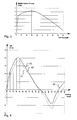
- Fig. 4 shows righting curves of an experimental round-bilge sailboat having a fin keel weighing 65% of the total weight of the solid on-board ballasts, completed by a movable ballast having the 35% remaining, ratio as defined in a preferred configuration for a 65' sailboat.
- the boat is equipped with an extra tank ballast system having a volumetric capacity of 300% of the volume of the full movable ballast tunnel, volume corresponding as made on race sailboats.
- Curve 41 shows the righting moment RM with the movable ballast inactive, i.e. positioned on the boat centre, or as if the boat was not equipped with it.
- Curve 42 shows the righting moment RM with the movable ballast active, the ballast beginning to move windward as early as 3° of heel, and moving on the other side once the boat is capsized over 90 degrees.
- Curve 43 shows the righting moment RM with the ballast tunnel inactive and the extra tank ballast system fully active, i.e. being refilled at 100% windward or yet 37% of its total volumetric capacity, the remaining percentage being positioned on the other side and aft.
- the movable ballast system is boosting up to 325% the original righting moment from as early 3° of heeling and boost yet up to 22% at 40° of heeling, i.e. it is changing radically the efficiency of the boat which gains the same proportion of sails power without having to overload, when the tank ballast system with race characteristics brought only 96% at 3° and 9% at 40°, having to load an extra mass.
Landscapes
- Chemical & Material Sciences (AREA)
- Engineering & Computer Science (AREA)
- Combustion & Propulsion (AREA)
- Mechanical Engineering (AREA)
- Ocean & Marine Engineering (AREA)
- Other Liquid Machine Or Engine Such As Wave Power Use (AREA)
Claims (10)
- Segelboot, das eine bewegliche Ballastanordnung aufweist, wobei die bewegliche Ballastanordnung (11) in einem Tunnel oder Kanal (12) angeordnet ist, der im Inneren und vorzugsweise nahe dem unteren Schiffskörper des Segelbootes vorhanden ist, und das außerdem Ballastgewichtselemente aufweist, die aus Blei bestehen, dadurch gekennzeichnet, dass der Tunnel oder Kanal (12) hermetisch abgedichtet ist, dadurch, dass der Tunnel oder Kanal (12) eine Hufeisenform aufweist, und dadurch, dass sich die Enden des Tunnels oder Kanals in Richtung des hinteren Abschnittes des Segelbootes erstrecken, und außerdem dadurch gekennzeichnet, dass die beweglichen Ballastgewichtselemente so ausgebildet sind, dass sie unabhängig voneinander verschoben werden können.
- Segelboot nach Anspruch 1, bei dem der hermetisch abgedichtete Tunnel oder Kanal (12) eine neutrale Atmosphäre enthält, vorzugsweise Stickstoff.
- Segelboot nach Anspruch 1, bei dem der Tunnel oder Kanal (12) im Schiffskörper gerade und/oder gebogene Segmente aufweist.
- Segelboot nach einem der vorhergehenden Ansprüche, bei dem der Tunnel oder Kanal (12) in der Form einer geschlossenen Schleife bereitgestellt wird.
- Segelboot nach einem der vorhergehenden Ansprüche, bei dem der Tunnel oder Kanal Seitenwände aufweist, die mit einem Satz von Schienen oder Laufbahnen für die beweglichen Ballastgewichtselemente versehen sind, und bei dem die beweglichen Ballastgewichtselemente als ein Gruppenverband bereitgestellt werden.
- Segelboot nach einem der vorhergehenden Ansprüche, bei dem die Betätigung der beweglichen Ballastgewichtselemente im Tunnel oder Kanal (12) manuell erfolgt.
- Segelboot nach einem der vorhergehenden Ansprüche, bei dem die Betätigung der beweglichen Ballastgewichtselemente im Tunnel oder Kanal (12) servounterstützt erfolgt.
- Segelboot nach einem der vorhergehenden Ansprüche, bei dem eine mechanische Kraft auf die beweglichen Ballastgewichtselemente angewandt wird.
- Segelboot nach einem der vorhergehenden Ansprüche, bei dem der Tunnel wie ein Zylinder und die Ballastgewichtselemente wie ein Kolben mit zwei Enden aufgebaut sind, und wobei der Ballast dadurch betätigt wird, dass ein Gas oder eine Flüssigkeit auf einer seiner Seiten unter Druck gesetzt wird und das Gas oder die Flüssigkeit auf seiner anderen Seite freigegeben wird.
- Segelboot nach Anspruch 9, bei dem der Kolben einen Gelenkkörper aufweist, der ihm gestattet, sich zwischen seinen zwei Enden zu biegen.
Priority Applications (1)
| Application Number | Priority Date | Filing Date | Title |
|---|---|---|---|
| PL07803086T PL2197734T3 (pl) | 2007-08-30 | 2007-08-30 | Przesuwny balast dla żaglówki i statku |
Applications Claiming Priority (1)
| Application Number | Priority Date | Filing Date | Title |
|---|---|---|---|
| PCT/EP2007/059078 WO2009026964A1 (en) | 2007-08-30 | 2007-08-30 | Movable ballast for sailboat and ship |
Publications (2)
| Publication Number | Publication Date |
|---|---|
| EP2197734A1 EP2197734A1 (de) | 2010-06-23 |
| EP2197734B1 true EP2197734B1 (de) | 2013-03-06 |
Family
ID=39370588
Family Applications (1)
| Application Number | Title | Priority Date | Filing Date |
|---|---|---|---|
| EP07803086A Active EP2197734B1 (de) | 2007-08-30 | 2007-08-30 | Bewegbarer ballast für ein segelboot und schiff |
Country Status (6)
| Country | Link |
|---|---|
| EP (1) | EP2197734B1 (de) |
| DK (1) | DK2197734T3 (de) |
| ES (1) | ES2413157T3 (de) |
| PL (1) | PL2197734T3 (de) |
| PT (1) | PT2197734E (de) |
| WO (1) | WO2009026964A1 (de) |
Families Citing this family (5)
| Publication number | Priority date | Publication date | Assignee | Title |
|---|---|---|---|---|
| CN102712350B (zh) * | 2009-09-04 | 2015-11-25 | 伊特雷科公司 | 海上风轮机安装 |
| LU91809B1 (en) | 2011-04-20 | 2012-10-22 | Vincent De Troz | Mobile ballast device |
| DE102016207419A1 (de) | 2016-04-29 | 2017-11-02 | Siemens Aktiengesellschaft | Wasserfahrzeug und Verfahren zum Betrieb eines Wasserfahrzeuges |
| WO2021202194A1 (en) * | 2020-03-28 | 2021-10-07 | Corcoran John F | Watercraft with battery ballast system |
| DE102022212600A1 (de) * | 2022-11-25 | 2024-04-11 | Zf Friedrichshafen Ag | Verfahren und System zum aktiven Stabilisieren eines Wasserfahrzeugs |
Family Cites Families (5)
| Publication number | Priority date | Publication date | Assignee | Title |
|---|---|---|---|---|
| US3698345A (en) * | 1970-12-28 | 1972-10-17 | Sperry Rand Corp | Active tank stabilizer for marine vessels |
| NO170400C (no) * | 1990-06-15 | 1992-10-14 | Sailmatic As | Avbalanseringssystem for seilbaat |
| FR2802504B1 (fr) * | 1999-12-20 | 2002-03-01 | Technicatome | Dispositif ameliore d'equilibrage d'un navire notamment en roulis |
| FR2802891B1 (fr) * | 1999-12-23 | 2002-05-03 | Bernard Canal | Dispositif destine a assurer une limitation de la gite des voiliers |
| AU2006201460B1 (en) * | 2006-04-07 | 2007-06-21 | Robert William Gale | Watercraft ballast |
-
2007
- 2007-08-30 EP EP07803086A patent/EP2197734B1/de active Active
- 2007-08-30 PL PL07803086T patent/PL2197734T3/pl unknown
- 2007-08-30 ES ES07803086T patent/ES2413157T3/es active Active
- 2007-08-30 DK DK07803086.3T patent/DK2197734T3/da active
- 2007-08-30 PT PT78030863T patent/PT2197734E/pt unknown
- 2007-08-30 WO PCT/EP2007/059078 patent/WO2009026964A1/en not_active Ceased
Also Published As
| Publication number | Publication date |
|---|---|
| PT2197734E (pt) | 2013-06-12 |
| DK2197734T3 (da) | 2013-05-27 |
| PL2197734T3 (pl) | 2013-09-30 |
| WO2009026964A1 (en) | 2009-03-05 |
| EP2197734A1 (de) | 2010-06-23 |
| ES2413157T3 (es) | 2013-07-15 |
Similar Documents
| Publication | Publication Date | Title |
|---|---|---|
| US9038554B2 (en) | Mobile ballast device | |
| US5163377A (en) | Sailing yacht | |
| CN100546870C (zh) | 不倾翻的船 | |
| US10913513B2 (en) | Catamaran type vessel | |
| KR101789009B1 (ko) | 선미에서 승ㆍ하강이 가능한 사이드 스러스터를 갖는 선박 | |
| EP2197734B1 (de) | Bewegbarer ballast für ein segelboot und schiff | |
| US3898946A (en) | Sea-going high-commercial-speed displacement vessel | |
| WO2015120862A1 (en) | A boat heel compensation method and system, and a boat with said system | |
| JPH09502680A (ja) | 潜水可能型ボート | |
| KR20010089684A (ko) | 반잠수가능한 중량 화물선 | |
| US4376416A (en) | Convertible sailboat/motorboat | |
| US10000258B2 (en) | Vessel with selectively deployable hull members | |
| JP2023526852A (ja) | 可変形状を備えた船体 | |
| KR102612234B1 (ko) | 공기윤활방식의 고속활주 선의 선형 | |
| US20160375971A1 (en) | Multihull Watercraft | |
| WO2011078737A2 (ru) | Способ перемещения судна в воде и судно для перемещения в воде по упомянутому способу перемещения | |
| KR102367115B1 (ko) | 대형 배수형 선체 선박 | |
| US11679841B2 (en) | Marine vessel with aft extension | |
| CN113998059A (zh) | 长江干线lng罐箱运输船 | |
| US6830003B2 (en) | Multihull boat | |
| WO1981000241A1 (fr) | Support propulsif de navigation semi-immerge | |
| ZA200808670B (en) | A submersible | |
| IT202300015687A1 (it) | Traghetto veloce con sostentamento ad aria ed idrodinamico | |
| AU781474B2 (en) | Wave avoidance yacht (way) | |
| RU2227104C2 (ru) | Способ маневрирования и способ торможения тримарана |
Legal Events
| Date | Code | Title | Description |
|---|---|---|---|
| PUAI | Public reference made under article 153(3) epc to a published international application that has entered the european phase |
Free format text: ORIGINAL CODE: 0009012 |
|
| 17P | Request for examination filed | ||
| AK | Designated contracting states | ||
| AX | Request for extension of the european patent | ||
| 17Q | First examination report despatched | ||
| DAX | Request for extension of the european patent (deleted) | ||
| GRAP | Despatch of communication of intention to grant a patent |
Free format text: ORIGINAL CODE: EPIDOSNIGR1 |
|
| GRAS | Grant fee paid |
Free format text: ORIGINAL CODE: EPIDOSNIGR3 |
|
| GRAA | (expected) grant |
Free format text: ORIGINAL CODE: 0009210 |
|
| AK | Designated contracting states | ||
| REG | Reference to a national code |
Ref country code: GB Ref legal event code: FG4D |
|
| REG | Reference to a national code |
Ref country code: AT Ref legal event code: REF Ref document number: 599439 Country of ref document: AT Kind code of ref document: T Effective date: 20130315 Ref country code: CH Ref legal event code: EP |
|
| REG | Reference to a national code |
Ref country code: IE Ref legal event code: FG4D |
|
| REG | Reference to a national code |
Ref country code: DE Ref legal event code: R096 Ref document number: 602007028915 Country of ref document: DE Effective date: 20130502 |
|
| REG | Reference to a national code |
Ref country code: DK Ref legal event code: T3 |
|
| REG | Reference to a national code |
Ref country code: PT Ref legal event code: SC4A Free format text: AVAILABILITY OF NATIONAL TRANSLATION Effective date: 20130604 |
|
| REG | Reference to a national code |
Ref country code: ES Ref legal event code: FG2A Ref document number: 2413157 Country of ref document: ES Kind code of ref document: T3 Effective date: 20130715 Ref country code: AT Ref legal event code: MK05 Ref document number: 599439 Country of ref document: AT Kind code of ref document: T Effective date: 20130306 |
|
| REG | Reference to a national code |
Ref country code: NL Ref legal event code: T3 |
|
| PG25 | Lapsed in a contracting state [announced via postgrant information from national office to epo] |
Ref country code: BG Free format text: LAPSE BECAUSE OF FAILURE TO SUBMIT A TRANSLATION OF THE DESCRIPTION OR TO PAY THE FEE WITHIN THE PRESCRIBED TIME-LIMIT Effective date: 20130606 Ref country code: LT Free format text: LAPSE BECAUSE OF FAILURE TO SUBMIT A TRANSLATION OF THE DESCRIPTION OR TO PAY THE FEE WITHIN THE PRESCRIBED TIME-LIMIT Effective date: 20130306 Ref country code: AT Free format text: LAPSE BECAUSE OF FAILURE TO SUBMIT A TRANSLATION OF THE DESCRIPTION OR TO PAY THE FEE WITHIN THE PRESCRIBED TIME-LIMIT Effective date: 20130306 Ref country code: SE Free format text: LAPSE BECAUSE OF FAILURE TO SUBMIT A TRANSLATION OF THE DESCRIPTION OR TO PAY THE FEE WITHIN THE PRESCRIBED TIME-LIMIT Effective date: 20130306 |
|
| REG | Reference to a national code |
Ref country code: LT Ref legal event code: MG4D |
|
| PG25 | Lapsed in a contracting state [announced via postgrant information from national office to epo] |
Ref country code: FI Free format text: LAPSE BECAUSE OF FAILURE TO SUBMIT A TRANSLATION OF THE DESCRIPTION OR TO PAY THE FEE WITHIN THE PRESCRIBED TIME-LIMIT Effective date: 20130306 Ref country code: GR Free format text: LAPSE BECAUSE OF FAILURE TO SUBMIT A TRANSLATION OF THE DESCRIPTION OR TO PAY THE FEE WITHIN THE PRESCRIBED TIME-LIMIT Effective date: 20130607 Ref country code: LV Free format text: LAPSE BECAUSE OF FAILURE TO SUBMIT A TRANSLATION OF THE DESCRIPTION OR TO PAY THE FEE WITHIN THE PRESCRIBED TIME-LIMIT Effective date: 20130306 Ref country code: SI Free format text: LAPSE BECAUSE OF FAILURE TO SUBMIT A TRANSLATION OF THE DESCRIPTION OR TO PAY THE FEE WITHIN THE PRESCRIBED TIME-LIMIT Effective date: 20130306 |
|
| PG25 | Lapsed in a contracting state [announced via postgrant information from national office to epo] |
Ref country code: BE Free format text: LAPSE BECAUSE OF FAILURE TO SUBMIT A TRANSLATION OF THE DESCRIPTION OR TO PAY THE FEE WITHIN THE PRESCRIBED TIME-LIMIT Effective date: 20130306 |
|
| REG | Reference to a national code |
Ref country code: PL Ref legal event code: T3 |
|
| PG25 | Lapsed in a contracting state [announced via postgrant information from national office to epo] |
Ref country code: IS Free format text: LAPSE BECAUSE OF FAILURE TO SUBMIT A TRANSLATION OF THE DESCRIPTION OR TO PAY THE FEE WITHIN THE PRESCRIBED TIME-LIMIT Effective date: 20130706 Ref country code: SK Free format text: LAPSE BECAUSE OF FAILURE TO SUBMIT A TRANSLATION OF THE DESCRIPTION OR TO PAY THE FEE WITHIN THE PRESCRIBED TIME-LIMIT Effective date: 20130306 Ref country code: CZ Free format text: LAPSE BECAUSE OF FAILURE TO SUBMIT A TRANSLATION OF THE DESCRIPTION OR TO PAY THE FEE WITHIN THE PRESCRIBED TIME-LIMIT Effective date: 20130306 Ref country code: RO Free format text: LAPSE BECAUSE OF FAILURE TO SUBMIT A TRANSLATION OF THE DESCRIPTION OR TO PAY THE FEE WITHIN THE PRESCRIBED TIME-LIMIT Effective date: 20130306 Ref country code: EE Free format text: LAPSE BECAUSE OF FAILURE TO SUBMIT A TRANSLATION OF THE DESCRIPTION OR TO PAY THE FEE WITHIN THE PRESCRIBED TIME-LIMIT Effective date: 20130306 |
|
| PGFP | Annual fee paid to national office [announced via postgrant information from national office to epo] |
Ref country code: FR Payment date: 20150630 Year of fee payment: 9 |
|
| PG25 | Lapsed in a contracting state [announced via postgrant information from national office to epo] |
Ref country code: CY Free format text: LAPSE BECAUSE OF FAILURE TO SUBMIT A TRANSLATION OF THE DESCRIPTION OR TO PAY THE FEE WITHIN THE PRESCRIBED TIME-LIMIT Effective date: 20130306 |
|
| PLBE | No opposition filed within time limit |
Free format text: ORIGINAL CODE: 0009261 |
|
| STAA | Information on the status of an ep patent application or granted ep patent |
Free format text: STATUS: NO OPPOSITION FILED WITHIN TIME LIMIT |
|
| 26N | No opposition filed | ||
| REG | Reference to a national code |
Ref country code: DE Ref legal event code: R097 Ref document number: 602007028915 Country of ref document: DE Effective date: 20131209 |
|
| REG | Reference to a national code |
Ref country code: CH Ref legal event code: PL |
|
| PG25 | Lapsed in a contracting state [announced via postgrant information from national office to epo] |
Ref country code: LI Free format text: LAPSE BECAUSE OF NON-PAYMENT OF DUE FEES Effective date: 20130831 Ref country code: CH Free format text: LAPSE BECAUSE OF NON-PAYMENT OF DUE FEES Effective date: 20130831 Ref country code: MC Free format text: LAPSE BECAUSE OF FAILURE TO SUBMIT A TRANSLATION OF THE DESCRIPTION OR TO PAY THE FEE WITHIN THE PRESCRIBED TIME-LIMIT Effective date: 20130306 |
|
| PG25 | Lapsed in a contracting state [announced via postgrant information from national office to epo] |
Ref country code: TR Free format text: LAPSE BECAUSE OF FAILURE TO SUBMIT A TRANSLATION OF THE DESCRIPTION OR TO PAY THE FEE WITHIN THE PRESCRIBED TIME-LIMIT Effective date: 20130306 Ref country code: MT Free format text: LAPSE BECAUSE OF FAILURE TO SUBMIT A TRANSLATION OF THE DESCRIPTION OR TO PAY THE FEE WITHIN THE PRESCRIBED TIME-LIMIT Effective date: 20130306 |
|
| PG25 | Lapsed in a contracting state [announced via postgrant information from national office to epo] |
Ref country code: HU Free format text: LAPSE BECAUSE OF FAILURE TO SUBMIT A TRANSLATION OF THE DESCRIPTION OR TO PAY THE FEE WITHIN THE PRESCRIBED TIME-LIMIT Effective date: 20070830 Ref country code: LU Free format text: LAPSE BECAUSE OF NON-PAYMENT OF DUE FEES Effective date: 20130830 |
|
| REG | Reference to a national code |
Ref country code: DE Ref legal event code: R119 Ref document number: 602007028915 Country of ref document: DE |
|
| REG | Reference to a national code |
Ref country code: PT Ref legal event code: MM4A Free format text: LAPSE DUE TO NON-PAYMENT OF FEES Effective date: 20160229 |
|
| REG | Reference to a national code |
Ref country code: DK Ref legal event code: EBP Effective date: 20150831 |
|
| GBPC | Gb: european patent ceased through non-payment of renewal fee | ||
| PG25 | Lapsed in a contracting state [announced via postgrant information from national office to epo] |
Ref country code: IT Free format text: LAPSE BECAUSE OF NON-PAYMENT OF DUE FEES Effective date: 20130830 |
|
| REG | Reference to a national code |
Ref country code: NL Ref legal event code: MM Effective date: 20150901 |
|
| PG25 | Lapsed in a contracting state [announced via postgrant information from national office to epo] |
Ref country code: PT Free format text: LAPSE BECAUSE OF NON-PAYMENT OF DUE FEES Effective date: 20160229 |
|
| REG | Reference to a national code |
Ref country code: IE Ref legal event code: MM4A |
|
| REG | Reference to a national code |
Ref country code: FR Ref legal event code: ST Effective date: 20160429 |
|
| PG25 | Lapsed in a contracting state [announced via postgrant information from national office to epo] |
Ref country code: NL Free format text: LAPSE BECAUSE OF NON-PAYMENT OF DUE FEES Effective date: 20150901 |
|
| PG25 | Lapsed in a contracting state [announced via postgrant information from national office to epo] |
Ref country code: GB Free format text: LAPSE BECAUSE OF NON-PAYMENT OF DUE FEES Effective date: 20150830 Ref country code: DE Free format text: LAPSE BECAUSE OF NON-PAYMENT OF DUE FEES Effective date: 20160301 Ref country code: IE Free format text: LAPSE BECAUSE OF NON-PAYMENT OF DUE FEES Effective date: 20150830 |
|
| PG25 | Lapsed in a contracting state [announced via postgrant information from national office to epo] |
Ref country code: DK Free format text: LAPSE BECAUSE OF NON-PAYMENT OF DUE FEES Effective date: 20150831 Ref country code: FR Free format text: LAPSE BECAUSE OF NON-PAYMENT OF DUE FEES Effective date: 20150831 |
|
| PG25 | Lapsed in a contracting state [announced via postgrant information from national office to epo] |
Ref country code: PL Free format text: LAPSE BECAUSE OF NON-PAYMENT OF DUE FEES Effective date: 20150830 |
|
| REG | Reference to a national code |
Ref country code: ES Ref legal event code: FG2A Effective date: 20161130 |
|
| PG25 | Lapsed in a contracting state [announced via postgrant information from national office to epo] |
Ref country code: ES Free format text: LAPSE BECAUSE OF NON-PAYMENT OF DUE FEES Effective date: 20150831 |