EP2197776B1 - Sicherheitschloss - Google Patents
Sicherheitschloss Download PDFInfo
- Publication number
- EP2197776B1 EP2197776B1 EP08840493.4A EP08840493A EP2197776B1 EP 2197776 B1 EP2197776 B1 EP 2197776B1 EP 08840493 A EP08840493 A EP 08840493A EP 2197776 B1 EP2197776 B1 EP 2197776B1
- Authority
- EP
- European Patent Office
- Prior art keywords
- safety
- lock
- fitted
- elevator
- switch
- Prior art date
- Legal status (The legal status is an assumption and is not a legal conclusion. Google has not performed a legal analysis and makes no representation as to the accuracy of the status listed.)
- Not-in-force
Links
- 210000003323 beak Anatomy 0.000 claims description 14
- 238000000034 method Methods 0.000 claims description 8
- 230000000694 effects Effects 0.000 claims description 5
- 230000001681 protective effect Effects 0.000 claims description 5
- 230000002940 repellent Effects 0.000 claims description 2
- 239000005871 repellent Substances 0.000 claims description 2
- 238000012544 monitoring process Methods 0.000 description 7
- 239000004020 conductor Substances 0.000 description 5
- 238000012512 characterization method Methods 0.000 description 3
- 238000005259 measurement Methods 0.000 description 2
- 229920003023 plastic Polymers 0.000 description 2
- 229910000831 Steel Inorganic materials 0.000 description 1
- 238000004519 manufacturing process Methods 0.000 description 1
- 239000000463 material Substances 0.000 description 1
- 239000010959 steel Substances 0.000 description 1
Images


Classifications
-
- B—PERFORMING OPERATIONS; TRANSPORTING
- B66—HOISTING; LIFTING; HAULING
- B66B—ELEVATORS; ESCALATORS OR MOVING WALKWAYS
- B66B13/00—Doors, gates, or other apparatus controlling access to, or exit from, cages or lift well landings
- B66B13/02—Door or gate operation
- B66B13/14—Control systems or devices
- B66B13/16—Door or gate locking devices controlled or primarily controlled by condition of cage, e.g. movement or position
- B66B13/165—Door or gate locking devices controlled or primarily controlled by condition of cage, e.g. movement or position electrical
-
- E—FIXED CONSTRUCTIONS
- E05—LOCKS; KEYS; WINDOW OR DOOR FITTINGS; SAFES
- E05B—LOCKS; ACCESSORIES THEREFOR; HANDCUFFS
- E05B65/00—Locks or fastenings for special use
Definitions
- the object of this invention is a safety lock as defined in the preamble of claim 1, a method for fitting the safety lock into the safety arrangement of an elevator as defined in the preamble of claim 12, and also an elevator as defined in the preamble of claim 15.
- Safety locks are used as a part of the safety arrangements of a building, e.g. in connection with the landing doors of an elevator.
- monitoring appliances with which the safety of the locking is verified, are needed in addition to the locking appliance in order to ensure safety.
- elevator regulators require that the locking system of the landing doors of an elevator must be monitored both by measuring the status of the locking and by measuring the position of the landing door to be locked.
- the position of the landing door is conventionally measured with a separate safety switch, which is fitted to open under forced control when the landing door opens.
- the aforementioned safety switch is installed separately to the landing door.
- Publication EP1441091 describes a safety lock, in which the operation of the manually-operated emergency release appliance is measured with a first safety switch and the locking is measured with a second safety switch.
- Publication EP1473511 describes a measuring arrangement implemented with Hall sensors e.g. for monitoring the position of a landing door.
- Publication EP1110900 describes a safety arrangement of the service spaces of an elevator shaft, wherein the safety device monitoring the position of the landing door is mechanically in connection with the door operator.
- document US1,896,541 relates to an electromechanical interlock for an elevator door having a bar which moves with the door upon a manually opening and closing thereof.
- an electromagnet which when energized moves a catch lock which in turn releases a detent. In case the detent is released, the bar then can be manually moved to open the door.
- the purpose of this invention is to disclose a new type of safety lock, in which both the monitoring of the locking and the measurement of the position of the landing door is done with a safety switch fitted inside the frame section of the safety lock.
- Another purpose of the invention is to present the fitting of a safety lock to the safety system of an elevator, more particularly in connection with the landing doors of the elevator.
- the safety lock according to the invention is characterized by what is disclosed in the characterization part of claim 1
- the method according to the invention for fitting the safety lock into the safety arrangement of an elevator is characterized by what is disclosed in the characterization part of claim 12
- the elevator according to the invention is characterized by what is disclosed in the characterization part of claim 15.
- Other embodiments of the invention are characterized by what is disclosed in the other claims. Some inventive embodiments are also discussed in the descriptive section of the present application.
- the safety lock comprises a frame section, and also a lock latch in connection with the frame section; additionally the safety lock comprises a catch lever guided via a guide interface, as well as a safety switch fitted inside the frame section.
- a beak part is made in connection with the guide groove of the lock latch, and the guide of the catch lever is fitted to move in the guide groove in relation to the lock latch in essentially the first position of the catch lever, and the guide of the catch lever is fitted to lock to the beak part in essentially the second position of the catch lever.
- a guide force by means of which the catch lever can be moved to a second position, can be exerted on the catch lever via the guide interface.
- the guide interface can comprise e.g.
- a safety switch in this context refers to a switch that opens under forced control, which can comprise one or more switch elements.
- the lock latch comprises a guide part, which guide part comprises a guide surface and also a guide groove.
- the safety switch comprises an operating lever of the safety switch, which operating lever of the safety switch is supported via a roller on the guide surface of the lock latch.
- the catch lever is fitted to turn around its hinge point and the catch lever comprises a guide, which is fitted into a guide groove.
- the catch lever comprises an arrester spring and also a closing magnet.
- the safety lock comprises a countermagnet of the closing magnet fitted into the door jamb, the polarity of which countermagnet is repellent to the closing magnet.
- the safety lock comprises a closing spring, which closing spring is fitted between the frame section and the lock latch.
- the safety lock comprises an operating lever of the lock latch, which operating lever is fitted to transmit a force effect exerted on itself to turn the lock latch in relation to the hinge point.
- the safety lock comprises a position switch (25), which is fitted to change its state on the basis of the position of the lock latch.
- the lock latch comprises a separate guide part, which guide part is fixed elsewhere on the lock latch.
- the safety lock comprises an electrical interface in the frame section.
- the safety switch comprises a protective casing, as well as a first and a second switch element fitted inside the protective casing.
- a frame section is fitted to the safety lock, and also a lock latch in connection with the frame section; a catch lever guided via the guide interface is fitted to the safety lock; and also a safety switch is fitted inside the frame section of the safety lock; a beak part is made in connection with the guide groove of the lock latch; the guide of the catch lever is fitted to move in the guide groove in relation to the lock latch in essentially the first position of the catch lever; and the guide of the catch lever is fitted to lock to the beak part in essentially the second position of the catch lever; the safety lock is fitted to the landing door of the elevator; and also a signal comprising the position data of the first switch element of the safety switch is taken to the safety circuit of the landing doors of the elevator via the electrical interface of the frame section.
- the aforementioned signal comprising the position data of the first switch element can be any prior-art signal whatsoever that indicates the position of the switch.
- the signal can be an analog signal or a digital signal, in parallel or serial form, and it can be transmitted with a signal conductor or e.g. wirelessly, in which case the electrical interface of the safety lock also comprises a transmitter.
- the aforementioned first switch element can also be fitted into the serial circuit together with the first switch elements of the safety switches of the other landing doors, in which case the aforementioned switch elements together comprise the safety circuit of the landing doors.
- the safety arrangement of the elevator is fitted to prevent, if necessary, movement of the elevator car by disconnecting the power supply to the elevator motor as well as by controlling the mechanical braking appliance of the elevator car on the basis of the position data of at least the first switch element of the safety switch; and the safety arrangement of the elevator is fitted to limit movement of the elevator car in the elevator shaft to outside the service spaces of the elevator shaft on the basis of the position data of at least the second switch element of the safety switch.
- the signal comprising the status data of the position switch of the lock is taken to the control of the door operator of the elevator car via the electrical interface of the frame section; and the door operator of the elevator car is fitted to be controlled on the basis of the signal comprising at least the aforementioned status data of the position switch of the lock.
- the elevator according to the invention comprises a safety lock fitted to a landing door of the elevator.
- the safety lock comprises: a frame section, and also a lock latch in connection with the frame section; a catch lever guided via a guide interface; and also a safety switch fitted inside the frame section.
- a beak part is made in connection with the guide groove of the lock latch, and the guide of the catch lever is fitted to move in the guide groove in relation to the lock latch in essentially the first position of the catch lever, and the guide of the catch lever is fitted to lock to the beak part in essentially the second position of the catch lever.
- the signal comprising the position data of the first switch element of the safety switch is taken to the safety circuit of the landing doors of the elevator via the electrical interface of the frame section of the safety switch.
- the aforementioned safety lock comprises two safety switches, of which the first safety switch comprises the aforementioned first switch element and the second safety switch comprises the aforementioned second switch element.
- both the first and the second switch element are fitted to change their switch status on the basis of the movement of the guide part of the lock latch.
- Fig. 1 presents a safety lock 1 according to the invention in the closed position.
- Fig. 2 presents a safety lock according to the invention in the open position.
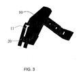
- Fig. 3 presents a guide part 9 of the lock latch according to the invention.
- the safety lock is here fitted to the landing door of the elevator.
- the safety lock 1 comprises a frame section 2 and also a lock latch 4 in connection with the frame section.
- the lock latch is fitted to turn around its hinge point 5.
- the lock latch comprises a stem part 6, a beak part 7 and also a separate guide part 9, which is fixed elsewhere on the lock latch.
- the guide part 9 is here a separate plastic part to the rest of the lock latch 4 to facilitate manufacture, but it can also be integrated into the rest of the lock latch.
- the guide part 9 comprises a guide surface 10 and also a guide groove 11.
- a beak part 20 is made in connection with the guide groove 11.
- the safety lock also comprises an operating lever 24, of the lock latch, which operating lever is fitted to transmit the force effect exerted on itself to turn the lock latch in relation to the hinge point 5.
- This force effect can, e.g. in an elevator system, be achieved with the door motor of the elevator, in which case the operating lever 24 of the lock latch is in connection elsewhere to the door operator of the elevator.
- the force effect can also be achieved e.g. manually with the emergency release appliance of the door.
- the safety lock also comprises a catch lever 3, by means of which the lock latch 4 can be latched into the open position when the door is open.
- the safety lock comprises a guide interface in which is a closing magnet 17 fixed to the catch lever. When the door is closed the pushing force from the counter magnet 19, which is fitted into the door jamb 18 at the position of the closing magnet, is exerted on the closing magnet 17.
- An arrester spring is fitted around the hinge point of the catch lever, which arrester spring in turn exerts a latching force on the catch lever 3 that opposes the pushing force of the closing magnet.
- the catch lever When the pushing force of the closing magnet starts to be exerted on the catch lever 3, the catch lever turns to essentially its first position 21, in which case the guide 15 of the catch lever is able to move in relation to the lock latch 4 in the guide groove 11. In the case the lock latch can turn freely and the lock can be opened and closed.
- the safety switch 8 comprises a first and a second switch element, that open under forced control, and in connection with these an operating lever 12 of the safety switch, which operating lever is supported via a roller 13 on the guide surface 10 of the lock latch.
- the operating lever 12 moves as the roller 13 moves along the guide surface when the lock latch is turned.
- the lock latch 4 is in the closed position the lock beak 7 is out, locking the door.
- the first and the second switch element of the safety switch 8 are closed.
- the operating lever 12 of the safety switch moves according to the movement of the guide surface 10, and the change in position of the operating lever forces the switch elements of the safety switch open. In this case the opened switch elements inform that the lock latch is in the open position.
- This information is transmitted to the safety arrangement of the elevator, in which the information is compared to at least the control command of the car door of the elevator, and if the information does not match, the safety arrangement deduces that the landing door has opened to the elevator shaft. In this case movement of the elevator car in the elevator shaft is limited.
- One of the two switch elements of the safety switch 8 is also in the safety circuit of the landing doors, so that opening of the switch element disconnects the safety circuit of the landing doors. In this case driving with the elevator is prevented by disconnecting the power supply to both the brake control circuit 29, 31 of the mechanical brake and to the elevator motor 27.
- the open switch elements of the safety switch 8 indicate the position of the landing door.
- the switch elements of the safety switch can change their state only after the landing door has closed, in which case locking of the lock latch is cancelled and the lock latch can be moved to the closed position.
- the safety lock 1 also comprises a closing spring 23, which is fitted between the frame section 2 and the lock latch 4.
- the closing spring exerts a force on the lock latch 4, which force endeavors to keep the lock latch in the closed position.
- the position switch 25 presented in Fig. 1 is disposed in the safety lock such that when the lock latch 4 moves to the open position, the guide part 9 presses against the position switch, in which case the position switch 25 changes its state on the basis of the position of the lock latch 4.
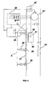
- Fig. 4 presents a safety arrangement of an elevator according to the invention.
- the elevator car 30 is moved in the elevator shaft 33 with an elevator motor 27 via elevator ropes.
- the power supply of the motor 27' is controlled with a frequency converter 28.
- safety locks according to the invention are fitted to the landing doors 26.
- the safety locks comprise safety switches 8 according to the invention, and the signal comprising the position data of the first switch element of each safety switch 8 is taken to the safety circuit 27 of the landing doors of the elevator via the electrical interface of the frame section 2.
- the safety circuit 27 in this embodiment of the invention comprises a safety circuit of first switch elements connected in series, and the first switch elements are connected to the safety circuit with conductors led through the electrical interface of the frame section of the safety lock.
- the signal comprising the position data of the second switch element of each safety switch 8 is taken by a conductor to the measuring circuit of the landing doors of the elevator via the electrical interface of the frame section 2 of the safety lock 1.
- the measuring circuit comprises a resistor 29 connected in parallel with each second switch element.
- the parallel connections of the resistors and the second switch elements are connected in series and connected to each other with conductors, and the position of the landing doors is determined by measuring the impedance of the serial circuit.
- the signal comprising the status data of the position switch element 25 of each safety lock 1 is taken, via the electrical interface of the frame section 2 of the lock, by a signal conductor to the control 32 of the door operator of the elevator car, and the control of the door operator receives information about the position of the landing door from the status data of the position switch 25.
- the safety arrangement of the elevator is fitted to prevent, if necessary, movement of the elevator car 30 by disconnecting the power supply to the elevator motor 27' as well as by controlling the mechanical braking appliance of the elevator car, such as a machinery brake 29' or a wedge brake 31 of the elevator car, on the basis of the position data of at least the first switch element of the safety switch 8.
- the safety arrangement of the elevator is also fitted to limit movement of the elevator car in the elevator shaft 33 to outside the service spaces of the elevator shaft on the basis of the position data of at least the second switch element of the safety switch 8.
- the safety lock according to the invention can be used generally for locking the doors in any building whatsoever, especially in situations in which the safety regulations require locking and monitoring of the position of the door to be locked.
Landscapes
- Engineering & Computer Science (AREA)
- Automation & Control Theory (AREA)
- Elevator Door Apparatuses (AREA)
Claims (15)
- Sicherheitsschloss (1), aufweisend:- eine Rahmensektion (2) und in Verbindung mit der Rahmensektion:- eine Schloss-Falle (4),- einen Fanghebel (3), der über eine Führungsverbindung gesteuert wird, und- einen Sicherheitsschalter (8), der innerhalb der Rahmensektion (2) eingepasst ist,wobei eine Nase (20) in Verbindung mit einer Führungsnut (11) der Schlossfalle (4) gefertigt ist und eine Führung (15) des Fanghebels eingepasst ist, um in der Führungsnut (11) in Relation zu der Schloss-Falle in im Wesentlichen eine erste Position des Fanghebels bewegbar zu sein, die eine Schließposition des Fanghebels (3) bedeutet, in der ein Schließen der Schloss-Falle (4) aufgehoben ist, dadurch gekennzeichnet, dass die Führung (15) des Fanghebels eingepasst ist, um die Nase (20) in im Wesentlichen einer zweiten Position (22) zu sperren, in der der Fanghebel (3) die Schloss-Falle (4) in einer Offen-Position sperrt.
- Sicherheitsschloss nach Anspruch 1, dadurch gekennzeichnet, dass die Schloss-Falle (4) ein Führungsteil (9) aufweist, welches Führungsteil eine Führungsfläche (10) wie auch eine Führungsnut (11) aufweist.
- Sicherheitsschloss nach Anspruch 1 oder 2, dadurch gekennzeichnet, dass der Sicherheitsschalter (8) einen Betätigungshebel (12) des Sicherheitsschalters aufweist, welcher Betätigungshebel des Sicherheitsschalters über eine Rolle (13) auf der Führungsfläche (10) der Schloss-Falle unterstützt ist.
- Sicherheitsschloss nach einem der vorangehenden Ansprüche, dadurch gekennzeichnet, dass der zuvor erwähnte Fanghebel (3) eingepasst ist, um um dessen Aufhängungspunkt zu drehen, und dass der Fanghebel eine Führung (15) aufweist, die in die Führungsnut (11) eingepasst ist.
- Sicherheitsschloss nach Anspruch 4, dadurch gekennzeichnet, dass der Fanghebel eine Haltefeder wie auch ein Schließmagnet (17) aufweist.
- Sicherheitsschloss nach einem der vorangehenden Ansprüche, dadurch gekennzeichnet, dass das Sicherheitsschloss ein Gegenmagnet (19) zum Schließmagnet aufweist, das innerhalb der Türlaibung (18) eingepasst ist, wobei die Polarität des Gegenmagnetes abstoßend auf das Schließmagnet (17) gewählt ist.
- Sicherheitsschloss nach einem der vorangehenden Ansprüche, dadurch gekennzeichnet, dass das Sicherheitsschloss einen Betätigungshebel (24) der Schlossfalle aufweist, der eingepasst ist, um die Kraftwirkung zu übertragen, die auf ihn selbst ausgeübt wird, um die Schloss-Falle (4) in Relation auf einen Aufhängungspunkt (5) zu drehen.
- Sicherheitsschloss nach einem der vorangehenden Ansprüche, dadurch gekennzeichnet, dass das Sicherheitsschloss einen Positionsschalter (25) aufweist, der eingepasst ist, um seinen Zustand auf der Grundlage der Position der Schloss-Falle (4) zu ändern.
- Sicherheitsschloss nach einem der vorangehenden Ansprüche, dadurch gekennzeichnet, dass die Schloss-Falle (4) ein separates Führungsteil (9) aufweist, welches Führungsteil irgendwo an der Schloss-Falle festgelegt ist.
- Sicherheitsschloss nach einem der vorangehenden Ansprüche, dadurch gekennzeichnet, dass das Sicherheitsschloss eine elektrische Schnittstelle innerhalb der Rahmensektion (2) aufweist.
- Sicherheitsschloss nach einem der vorangehenden Ansprüche, dadurch gekennzeichnet, dass der zuvor erwähnte Sicherheitsschalter (8) ein Schutzgehäuse aufweist, wie auch ein erstes und ein zweites Schaltelement, die innerhalb des Schutzgehäuses eingepasst sind.
- Verfahren zum Einpassen eines Sicherheitsschlosses (1) in die Sicherheitsanlage eines Aufzuges, wobei:- eine Rahmensektion (2) für das Sicherheitsschloss (1) vorgesehen wird, und ebenso eine Schloss-Falle (4) in Verbindung mit der Rahmensektion,- ein über eine Führungs-Verbindung (17, 19) geführter Fanghebel (3) in dem Sicherheitsschloss (1) eingepasst wird, und- ein Sicherheitsschalter (8) innerhalb der Rahmensektion (2) des Sicherheitsschlosses eingepasst wird,- eine Nase (20) in Verbindung mit einer Führungsnut (11) der Schloss-Falle (4) gefertigt wird,- eine Führung (15) des Fanghebels (3) eingepasst wird, um in der Führungsnut (11) in Relation zu der Schloss-Falle (4) in im Wesentlichen einer ersten Position (21) des Fanghebels bewegbar zu sein, was einer Schließposition des Fanghebels (3) entspricht, in der ein Schließen der Schloss-Falle (4) aufgehoben ist, und- die Führung (15) des Fanghebels eingepasst ist, um die Nase (20) in im Wesentlichen einer zweiten Position (22) des Fanghebels zu schließen, gleichbedeutend damit, dass der Fanghebel (3) die Schloss-Falle (4) in einer Offen-Position sperrt,- das Sicherheitsschloss für eine Geschosstür (26) des Aufzuges eingepasst wird,- ein Signal entnommen wird, dass die Positions-Daten eines ersten Schaltelements des Sicherheitsschalters (8) aufweist, um dieses einem Sicherheitskreis (27) für Geschosstüren des Aufzuges über die elektrische Schnittstelle der Rahmensektion zuzuführen.
- Verfahren nach Anspruch 12, dadurch gekennzeichnet, dass:- das die Positionsdaten eines zweiten Schaltelements des Sicherheitsschalters (8) aufweisende Signal wird dem Messkreis der Geschosstüren des Aufzuges über die elektrische Schnittstelle der Rahmensektion zugeführt.
- Verfahren nach Anspruch 12 oder 13, dadurch gekennzeichnet, dass:- die Sicherheitsanlage des Aufzuges dazu eingepasst ist, um bei Bedarf eine Bewegung der Aufzugskabine (30) zu verhindern, indem eine Stromzufuhr an einen Aufzugsmotor (27) unterbrochen wird, wie auch durch Steuern einer mechanischen Bremsvorrichtung (29, 31) einer Aufzugskabine auf der Grundlage der Positionsdaten von zumindest dem ersten Schaltelement des Sicherheitsschalters (8),- die Sicherheitsanlage eines Aufzuges eingepasst ist, um die Bewegung der Aufzugskabine in einem Aufzugsschacht (33) nach außerhalb der Serviceräume des Aufzugsschachtes zu begrenzen, und zwar auf der Grundlage der Positionsdaten von zumindest dem zweiten Schaltelement des Sicherheitsschalters (8).
- Aufzug, der ein Sicherheitsschloss (1) nach Anspruch 1 aufweist, eingepasst für eine Geschosstür (26) des Aufzuges, dadurch gekennzeichnet, dass ein die Positionsdaten eines ersten Schaltelementes eines Sicherheitsschalters (8) aufweisende Signal an einen Sicherheitskreis (27) von Geschosstüren des Aufzuges über eine elektrische Schnittstelle der Rahmensektion des Sicherheitsschalters geführt wird.
Applications Claiming Priority (2)
| Application Number | Priority Date | Filing Date | Title |
|---|---|---|---|
| FI20070787A FI121668B (fi) | 2007-10-19 | 2007-10-19 | Turvalukko sekä menetelmä turvalukon sovittamiseksi hissin turvajärjestelyyn |
| PCT/FI2008/000112 WO2009050328A1 (en) | 2007-10-19 | 2008-10-15 | Safety lock |
Publications (3)
| Publication Number | Publication Date |
|---|---|
| EP2197776A1 EP2197776A1 (de) | 2010-06-23 |
| EP2197776A4 EP2197776A4 (de) | 2013-10-09 |
| EP2197776B1 true EP2197776B1 (de) | 2015-12-23 |
Family
ID=38656799
Family Applications (1)
| Application Number | Title | Priority Date | Filing Date |
|---|---|---|---|
| EP08840493.4A Not-in-force EP2197776B1 (de) | 2007-10-19 | 2008-10-15 | Sicherheitschloss |
Country Status (4)
| Country | Link |
|---|---|
| EP (1) | EP2197776B1 (de) |
| DK (1) | DK2197776T3 (de) |
| FI (1) | FI121668B (de) |
| WO (1) | WO2009050328A1 (de) |
Families Citing this family (5)
| Publication number | Priority date | Publication date | Assignee | Title |
|---|---|---|---|---|
| DE102010010007B4 (de) | 2010-03-02 | 2018-05-03 | Janzhoff Aufzüge GmbH | Sicherungseinrichtung für Aufzüge |
| EP3292063B1 (de) | 2015-05-07 | 2021-07-14 | Otis Elevator Company | Schachtzugangssteuerung für aufzugssystem |
| US11479989B2 (en) | 2017-06-01 | 2022-10-25 | Interlock Usa, Inc. | Lever action automatic shootbolt operator with magnetically-triggered locking mechanism |
| AU2018278345B2 (en) | 2017-06-01 | 2023-05-25 | Assa Abloy Fenestration Llc | Magnetically-triggered lock mechanism |
| US12163356B2 (en) | 2017-06-01 | 2024-12-10 | Interlock Usa, Inc. | Lever action automatic shootbolt operator with magnetically-triggered lock mechanism |
Family Cites Families (4)
| Publication number | Priority date | Publication date | Assignee | Title |
|---|---|---|---|---|
| US1896541A (en) * | 1929-04-29 | 1933-02-07 | Otis Elevator Co | Electromechanical interlock |
| US2307542A (en) * | 1942-03-18 | 1943-01-05 | Otis Elevator Co | Interlock for elevator doors |
| NL6514354A (de) * | 1965-02-26 | 1966-08-29 | ||
| DE10301325B4 (de) * | 2003-01-15 | 2012-04-12 | Hans & Jos. Kronenberg Gmbh | Türverschluss mit Notentriegelung |
-
2007
- 2007-10-19 FI FI20070787A patent/FI121668B/fi not_active IP Right Cessation
-
2008
- 2008-10-15 DK DK08840493.4T patent/DK2197776T3/en active
- 2008-10-15 EP EP08840493.4A patent/EP2197776B1/de not_active Not-in-force
- 2008-10-15 WO PCT/FI2008/000112 patent/WO2009050328A1/en not_active Ceased
Also Published As
| Publication number | Publication date |
|---|---|
| EP2197776A4 (de) | 2013-10-09 |
| EP2197776A1 (de) | 2010-06-23 |
| FI20070787A0 (fi) | 2007-10-19 |
| DK2197776T3 (en) | 2016-01-11 |
| FI20070787L (fi) | 2009-04-20 |
| FI121668B (fi) | 2011-02-28 |
| WO2009050328A1 (en) | 2009-04-23 |
Similar Documents
| Publication | Publication Date | Title |
|---|---|---|
| EP2121500B1 (de) | Regler für unerwünschte bewegungen | |
| FI103498B (fi) | Järjestely hissikoneiston jarrun avaamiseen | |
| EP2197776B1 (de) | Sicherheitschloss | |
| CN104144868B (zh) | 用于电梯箱的位置采集的装置和用于运行电梯设备的方法 | |
| EP2421784B1 (de) | Sicherheitsanordnung für einen aufzug | |
| CA2829142C (en) | Electric door operator | |
| US10882720B2 (en) | Elevator car door interlock | |
| MXPA04009366A (es) | Sistema de vigilancia de cubo para elevador. | |
| SG178533A1 (en) | Method and arrangement for preventing the drifting of an elevator car | |
| EP2763925B1 (de) | Aufzugbremssteuerung | |
| US7228804B2 (en) | Door system for transit vehicle utilizing compression lock arrangement | |
| AU765681B2 (en) | Device for operating elevators in a special mode | |
| US20200032548A1 (en) | Door switch arrangement for a lavatory door device of an aircraft | |
| US20240034593A1 (en) | Elevator, method for controlling an elevator | |
| CN117836232A (zh) | 监控电梯门操作 | |
| EP0557861A2 (de) | Fernüberwachungseinrichtung für Sicherheitstüre und dergleichen | |
| CN110217674B (zh) | 电梯的电梯进入系统 | |
| EP3336039A1 (de) | Zugangsverhinderungssysteme für schlösser von aufzugsanlagen | |
| KR102148113B1 (ko) | 다중 모터 호환 기능 및 다중 프로토콜 지원 기능을 구비한 승강장안전문의 개별제어반 | |
| CN105197701B (zh) | 用于电梯的控制面板 | |
| EP4062020B1 (de) | Eckklammer | |
| CN116194399B (zh) | 用于控制电梯设备中的影响安全的ucm和udm功能的安全装置 | |
| WO2007020326A1 (en) | Elevator system | |
| CN121219221A (zh) | 操作电梯门 | |
| CN117585551A (zh) | 电梯坑维护系统 |
Legal Events
| Date | Code | Title | Description |
|---|---|---|---|
| PUAI | Public reference made under article 153(3) epc to a published international application that has entered the european phase |
Free format text: ORIGINAL CODE: 0009012 |
|
| 17P | Request for examination filed |
Effective date: 20100330 |
|
| AK | Designated contracting states |
Kind code of ref document: A1 Designated state(s): AT BE BG CH CY CZ DE DK EE ES FI FR GB GR HR HU IE IS IT LI LT LU LV MC MT NL NO PL PT RO SE SI SK TR |
|
| AX | Request for extension of the european patent |
Extension state: AL BA MK RS |
|
| DAX | Request for extension of the european patent (deleted) | ||
| A4 | Supplementary search report drawn up and despatched |
Effective date: 20130905 |
|
| RIC1 | Information provided on ipc code assigned before grant |
Ipc: B66B 13/16 20060101AFI20130830BHEP Ipc: E05B 65/00 20060101ALI20130830BHEP |
|
| 17Q | First examination report despatched |
Effective date: 20140205 |
|
| GRAP | Despatch of communication of intention to grant a patent |
Free format text: ORIGINAL CODE: EPIDOSNIGR1 |
|
| INTG | Intention to grant announced |
Effective date: 20150626 |
|
| GRAR | Information related to intention to grant a patent recorded |
Free format text: ORIGINAL CODE: EPIDOSNIGR71 |
|
| GRAS | Grant fee paid |
Free format text: ORIGINAL CODE: EPIDOSNIGR3 |
|
| INTG | Intention to grant announced |
Effective date: 20150917 |
|
| GRAA | (expected) grant |
Free format text: ORIGINAL CODE: 0009210 |
|
| AK | Designated contracting states |
Kind code of ref document: B1 Designated state(s): AT BE BG CH CY CZ DE DK EE ES FI FR GB GR HR HU IE IS IT LI LT LU LV MC MT NL NO PL PT RO SE SI SK TR |
|
| REG | Reference to a national code |
Ref country code: GB Ref legal event code: FG4D |
|
| REG | Reference to a national code |
Ref country code: CH Ref legal event code: EP |
|
| REG | Reference to a national code |
Ref country code: DK Ref legal event code: T3 Effective date: 20160110 |
|
| REG | Reference to a national code |
Ref country code: IE Ref legal event code: FG4D |
|
| REG | Reference to a national code |
Ref country code: AT Ref legal event code: REF Ref document number: 766464 Country of ref document: AT Kind code of ref document: T Effective date: 20160115 |
|
| REG | Reference to a national code |
Ref country code: DE Ref legal event code: R096 Ref document number: 602008041702 Country of ref document: DE |
|
| REG | Reference to a national code |
Ref country code: SE Ref legal event code: TRGR |
|
| REG | Reference to a national code |
Ref country code: LT Ref legal event code: MG4D |
|
| REG | Reference to a national code |
Ref country code: NL Ref legal event code: MP Effective date: 20151223 |
|
| PG25 | Lapsed in a contracting state [announced via postgrant information from national office to epo] |
Ref country code: HR Free format text: LAPSE BECAUSE OF FAILURE TO SUBMIT A TRANSLATION OF THE DESCRIPTION OR TO PAY THE FEE WITHIN THE PRESCRIBED TIME-LIMIT Effective date: 20151223 Ref country code: NO Free format text: LAPSE BECAUSE OF FAILURE TO SUBMIT A TRANSLATION OF THE DESCRIPTION OR TO PAY THE FEE WITHIN THE PRESCRIBED TIME-LIMIT Effective date: 20160323 Ref country code: LT Free format text: LAPSE BECAUSE OF FAILURE TO SUBMIT A TRANSLATION OF THE DESCRIPTION OR TO PAY THE FEE WITHIN THE PRESCRIBED TIME-LIMIT Effective date: 20151223 |
|
| REG | Reference to a national code |
Ref country code: AT Ref legal event code: MK05 Ref document number: 766464 Country of ref document: AT Kind code of ref document: T Effective date: 20151223 |
|
| PG25 | Lapsed in a contracting state [announced via postgrant information from national office to epo] |
Ref country code: LV Free format text: LAPSE BECAUSE OF FAILURE TO SUBMIT A TRANSLATION OF THE DESCRIPTION OR TO PAY THE FEE WITHIN THE PRESCRIBED TIME-LIMIT Effective date: 20151223 Ref country code: GR Free format text: LAPSE BECAUSE OF FAILURE TO SUBMIT A TRANSLATION OF THE DESCRIPTION OR TO PAY THE FEE WITHIN THE PRESCRIBED TIME-LIMIT Effective date: 20160324 Ref country code: FI Free format text: LAPSE BECAUSE OF FAILURE TO SUBMIT A TRANSLATION OF THE DESCRIPTION OR TO PAY THE FEE WITHIN THE PRESCRIBED TIME-LIMIT Effective date: 20151223 Ref country code: NL Free format text: LAPSE BECAUSE OF FAILURE TO SUBMIT A TRANSLATION OF THE DESCRIPTION OR TO PAY THE FEE WITHIN THE PRESCRIBED TIME-LIMIT Effective date: 20151223 |
|
| PG25 | Lapsed in a contracting state [announced via postgrant information from national office to epo] |
Ref country code: ES Free format text: LAPSE BECAUSE OF FAILURE TO SUBMIT A TRANSLATION OF THE DESCRIPTION OR TO PAY THE FEE WITHIN THE PRESCRIBED TIME-LIMIT Effective date: 20151223 Ref country code: IT Free format text: LAPSE BECAUSE OF FAILURE TO SUBMIT A TRANSLATION OF THE DESCRIPTION OR TO PAY THE FEE WITHIN THE PRESCRIBED TIME-LIMIT Effective date: 20151223 Ref country code: CZ Free format text: LAPSE BECAUSE OF FAILURE TO SUBMIT A TRANSLATION OF THE DESCRIPTION OR TO PAY THE FEE WITHIN THE PRESCRIBED TIME-LIMIT Effective date: 20151223 |
|
| PG25 | Lapsed in a contracting state [announced via postgrant information from national office to epo] |
Ref country code: SK Free format text: LAPSE BECAUSE OF FAILURE TO SUBMIT A TRANSLATION OF THE DESCRIPTION OR TO PAY THE FEE WITHIN THE PRESCRIBED TIME-LIMIT Effective date: 20151223 Ref country code: AT Free format text: LAPSE BECAUSE OF FAILURE TO SUBMIT A TRANSLATION OF THE DESCRIPTION OR TO PAY THE FEE WITHIN THE PRESCRIBED TIME-LIMIT Effective date: 20151223 Ref country code: RO Free format text: LAPSE BECAUSE OF FAILURE TO SUBMIT A TRANSLATION OF THE DESCRIPTION OR TO PAY THE FEE WITHIN THE PRESCRIBED TIME-LIMIT Effective date: 20151223 Ref country code: PL Free format text: LAPSE BECAUSE OF FAILURE TO SUBMIT A TRANSLATION OF THE DESCRIPTION OR TO PAY THE FEE WITHIN THE PRESCRIBED TIME-LIMIT Effective date: 20151223 Ref country code: EE Free format text: LAPSE BECAUSE OF FAILURE TO SUBMIT A TRANSLATION OF THE DESCRIPTION OR TO PAY THE FEE WITHIN THE PRESCRIBED TIME-LIMIT Effective date: 20151223 Ref country code: PT Free format text: LAPSE BECAUSE OF FAILURE TO SUBMIT A TRANSLATION OF THE DESCRIPTION OR TO PAY THE FEE WITHIN THE PRESCRIBED TIME-LIMIT Effective date: 20160426 Ref country code: IS Free format text: LAPSE BECAUSE OF FAILURE TO SUBMIT A TRANSLATION OF THE DESCRIPTION OR TO PAY THE FEE WITHIN THE PRESCRIBED TIME-LIMIT Effective date: 20160423 |
|
| REG | Reference to a national code |
Ref country code: DE Ref legal event code: R097 Ref document number: 602008041702 Country of ref document: DE |
|
| PLBE | No opposition filed within time limit |
Free format text: ORIGINAL CODE: 0009261 |
|
| STAA | Information on the status of an ep patent application or granted ep patent |
Free format text: STATUS: NO OPPOSITION FILED WITHIN TIME LIMIT |
|
| 26N | No opposition filed |
Effective date: 20160926 |
|
| PG25 | Lapsed in a contracting state [announced via postgrant information from national office to epo] |
Ref country code: BE Free format text: LAPSE BECAUSE OF FAILURE TO SUBMIT A TRANSLATION OF THE DESCRIPTION OR TO PAY THE FEE WITHIN THE PRESCRIBED TIME-LIMIT Effective date: 20151223 |
|
| PG25 | Lapsed in a contracting state [announced via postgrant information from national office to epo] |
Ref country code: SI Free format text: LAPSE BECAUSE OF FAILURE TO SUBMIT A TRANSLATION OF THE DESCRIPTION OR TO PAY THE FEE WITHIN THE PRESCRIBED TIME-LIMIT Effective date: 20151223 |
|
| REG | Reference to a national code |
Ref country code: CH Ref legal event code: PL |
|
| GBPC | Gb: european patent ceased through non-payment of renewal fee |
Effective date: 20161015 |
|
| REG | Reference to a national code |
Ref country code: IE Ref legal event code: MM4A |
|
| REG | Reference to a national code |
Ref country code: FR Ref legal event code: ST Effective date: 20170630 |
|
| PG25 | Lapsed in a contracting state [announced via postgrant information from national office to epo] |
Ref country code: CH Free format text: LAPSE BECAUSE OF NON-PAYMENT OF DUE FEES Effective date: 20161031 Ref country code: FR Free format text: LAPSE BECAUSE OF NON-PAYMENT OF DUE FEES Effective date: 20161102 Ref country code: LI Free format text: LAPSE BECAUSE OF NON-PAYMENT OF DUE FEES Effective date: 20161031 Ref country code: GB Free format text: LAPSE BECAUSE OF NON-PAYMENT OF DUE FEES Effective date: 20161015 |
|
| PG25 | Lapsed in a contracting state [announced via postgrant information from national office to epo] |
Ref country code: LU Free format text: LAPSE BECAUSE OF NON-PAYMENT OF DUE FEES Effective date: 20161015 |
|
| PG25 | Lapsed in a contracting state [announced via postgrant information from national office to epo] |
Ref country code: IE Free format text: LAPSE BECAUSE OF NON-PAYMENT OF DUE FEES Effective date: 20161015 |
|
| PG25 | Lapsed in a contracting state [announced via postgrant information from national office to epo] |
Ref country code: CY Free format text: LAPSE BECAUSE OF FAILURE TO SUBMIT A TRANSLATION OF THE DESCRIPTION OR TO PAY THE FEE WITHIN THE PRESCRIBED TIME-LIMIT Effective date: 20151223 Ref country code: HU Free format text: LAPSE BECAUSE OF FAILURE TO SUBMIT A TRANSLATION OF THE DESCRIPTION OR TO PAY THE FEE WITHIN THE PRESCRIBED TIME-LIMIT; INVALID AB INITIO Effective date: 20081015 |
|
| PG25 | Lapsed in a contracting state [announced via postgrant information from national office to epo] |
Ref country code: MC Free format text: LAPSE BECAUSE OF FAILURE TO SUBMIT A TRANSLATION OF THE DESCRIPTION OR TO PAY THE FEE WITHIN THE PRESCRIBED TIME-LIMIT Effective date: 20151223 Ref country code: MT Free format text: LAPSE BECAUSE OF NON-PAYMENT OF DUE FEES Effective date: 20161031 |
|
| PG25 | Lapsed in a contracting state [announced via postgrant information from national office to epo] |
Ref country code: BG Free format text: LAPSE BECAUSE OF FAILURE TO SUBMIT A TRANSLATION OF THE DESCRIPTION OR TO PAY THE FEE WITHIN THE PRESCRIBED TIME-LIMIT Effective date: 20151223 |
|
| PGFP | Annual fee paid to national office [announced via postgrant information from national office to epo] |
Ref country code: TR Payment date: 20180925 Year of fee payment: 11 |
|
| PGFP | Annual fee paid to national office [announced via postgrant information from national office to epo] |
Ref country code: SE Payment date: 20181019 Year of fee payment: 11 Ref country code: DE Payment date: 20181019 Year of fee payment: 11 Ref country code: DK Payment date: 20181023 Year of fee payment: 11 |
|
| REG | Reference to a national code |
Ref country code: DE Ref legal event code: R119 Ref document number: 602008041702 Country of ref document: DE |
|
| REG | Reference to a national code |
Ref country code: DK Ref legal event code: EBP Effective date: 20191031 |
|
| PG25 | Lapsed in a contracting state [announced via postgrant information from national office to epo] |
Ref country code: DE Free format text: LAPSE BECAUSE OF NON-PAYMENT OF DUE FEES Effective date: 20200501 |
|
| PG25 | Lapsed in a contracting state [announced via postgrant information from national office to epo] |
Ref country code: SE Free format text: LAPSE BECAUSE OF NON-PAYMENT OF DUE FEES Effective date: 20191016 |
|
| PG25 | Lapsed in a contracting state [announced via postgrant information from national office to epo] |
Ref country code: DK Free format text: LAPSE BECAUSE OF NON-PAYMENT OF DUE FEES Effective date: 20191031 |
|
| PG25 | Lapsed in a contracting state [announced via postgrant information from national office to epo] |
Ref country code: TR Free format text: LAPSE BECAUSE OF NON-PAYMENT OF DUE FEES Effective date: 20191015 |