EP2198103B1 - Charniere pour une boite porte-bagages ou analogue - Google Patents
Charniere pour une boite porte-bagages ou analogue Download PDFInfo
- Publication number
- EP2198103B1 EP2198103B1 EP08804903.6A EP08804903A EP2198103B1 EP 2198103 B1 EP2198103 B1 EP 2198103B1 EP 08804903 A EP08804903 A EP 08804903A EP 2198103 B1 EP2198103 B1 EP 2198103B1
- Authority
- EP
- European Patent Office
- Prior art keywords
- hinge
- bearing bush
- hinge leaf
- damper
- leaf
- Prior art date
- Legal status (The legal status is an assumption and is not a legal conclusion. Google has not performed a legal analysis and makes no representation as to the accuracy of the status listed.)
- Active
Links
Images

Classifications
-
- E—FIXED CONSTRUCTIONS
- E05—LOCKS; KEYS; WINDOW OR DOOR FITTINGS; SAFES
- E05F—DEVICES FOR MOVING WINGS INTO OPEN OR CLOSED POSITION; CHECKS FOR WINGS; WING FITTINGS NOT OTHERWISE PROVIDED FOR, CONCERNED WITH THE FUNCTIONING OF THE WING
- E05F1/00—Closers or openers for wings, not otherwise provided for in this subclass
- E05F1/08—Closers or openers for wings, not otherwise provided for in this subclass spring-actuated, e.g. for horizontally sliding wings
- E05F1/10—Closers or openers for wings, not otherwise provided for in this subclass spring-actuated, e.g. for horizontally sliding wings for swinging wings, e.g. counterbalance
- E05F1/12—Mechanisms in the shape of hinges or pivots, operated by springs
- E05F1/1207—Mechanisms in the shape of hinges or pivots, operated by springs with a coil spring parallel with the pivot axis
-
- E—FIXED CONSTRUCTIONS
- E05—LOCKS; KEYS; WINDOW OR DOOR FITTINGS; SAFES
- E05F—DEVICES FOR MOVING WINGS INTO OPEN OR CLOSED POSITION; CHECKS FOR WINGS; WING FITTINGS NOT OTHERWISE PROVIDED FOR, CONCERNED WITH THE FUNCTIONING OF THE WING
- E05F3/00—Closers or openers with braking devices, e.g. checks; Construction of pneumatic or liquid braking devices
- E05F3/14—Closers or openers with braking devices, e.g. checks; Construction of pneumatic or liquid braking devices with fluid brakes of the rotary type
-
- E—FIXED CONSTRUCTIONS
- E05—LOCKS; KEYS; WINDOW OR DOOR FITTINGS; SAFES
- E05Y—INDEXING SCHEME ASSOCIATED WITH SUBCLASSES E05D AND E05F, RELATING TO CONSTRUCTION ELEMENTS, ELECTRIC CONTROL, POWER SUPPLY, POWER SIGNAL OR TRANSMISSION, USER INTERFACES, MOUNTING OR COUPLING, DETAILS, ACCESSORIES, AUXILIARY OPERATIONS NOT OTHERWISE PROVIDED FOR, APPLICATION THEREOF
- E05Y2201/00—Constructional elements; Accessories therefor
- E05Y2201/20—Brakes; Disengaging means; Holders; Stops; Valves; Accessories therefor
- E05Y2201/21—Brakes
-
- E—FIXED CONSTRUCTIONS
- E05—LOCKS; KEYS; WINDOW OR DOOR FITTINGS; SAFES
- E05Y—INDEXING SCHEME ASSOCIATED WITH SUBCLASSES E05D AND E05F, RELATING TO CONSTRUCTION ELEMENTS, ELECTRIC CONTROL, POWER SUPPLY, POWER SIGNAL OR TRANSMISSION, USER INTERFACES, MOUNTING OR COUPLING, DETAILS, ACCESSORIES, AUXILIARY OPERATIONS NOT OTHERWISE PROVIDED FOR, APPLICATION THEREOF
- E05Y2201/00—Constructional elements; Accessories therefor
- E05Y2201/20—Brakes; Disengaging means; Holders; Stops; Valves; Accessories therefor
- E05Y2201/252—Type of friction
- E05Y2201/254—Fluid or viscous friction
- E05Y2201/256—Fluid or viscous friction with pistons or vanes
-
- E—FIXED CONSTRUCTIONS
- E05—LOCKS; KEYS; WINDOW OR DOOR FITTINGS; SAFES
- E05Y—INDEXING SCHEME ASSOCIATED WITH SUBCLASSES E05D AND E05F, RELATING TO CONSTRUCTION ELEMENTS, ELECTRIC CONTROL, POWER SUPPLY, POWER SIGNAL OR TRANSMISSION, USER INTERFACES, MOUNTING OR COUPLING, DETAILS, ACCESSORIES, AUXILIARY OPERATIONS NOT OTHERWISE PROVIDED FOR, APPLICATION THEREOF
- E05Y2201/00—Constructional elements; Accessories therefor
- E05Y2201/20—Brakes; Disengaging means; Holders; Stops; Valves; Accessories therefor
- E05Y2201/262—Type of motion, e.g. braking
- E05Y2201/266—Type of motion, e.g. braking rotary
Definitions
- the invention relates to a hinge for a luggage box od.
- Art. The preamble of independent claim 1 is based on the prior art according to the document US 2002/078529 A1 , which will be discussed in more detail below.
- Such a hinge has a first hinge leaf 11 and a smaller second hinge leaf 12.
- the latter is insertable into a holder 20.
- the holder 20 is not of interest here. He is in detail in the above-mentioned document DE 203 08 234 U1 shown and described.
- the second hinge leaf 12 has a first bearing bush 15a and a second bearing bush 15b, between which a bearing bush 15c of the first hinge leaf 11 is rotatable about a common hinge axis 22.
- An axle tube 13 is rotatably connected to the bearing bush 15c of the first hinge leaf 11, in the case shown by an outer toothing, not shown, on the circumference of the axle tube 13, which engages positively in an internal toothing of the bearing bush 15c.
- the axle tube 13 is rotatably storable.
- the axle tube 13 is rotatably connected to the first bearing bush 15a of the second hinge leaf 12 by a disc-shaped torque arm 14a and a cylindrical pin 14b.
- a torsion spring 18 is disposed in the axle tube 13 and fixed at one end to the axle tube. As shown in Fig. 7 the axle tube 13 is closed at its upper end and the bent end of the torsion spring 18 arranged therein is connected to the axle tube 13 by a cylindrical pin 14c.
- the torque arm 14 a and the cylinder pin 14 b connect the other end of the torsion spring 18 rotationally fixed to the second hinge leaf 12, as also shown in FIG Fig. 7 is shown.
- a generally designated 16 damper for the hinge movement which in principle from the above document DE 298 08 910 U1 has known structure is connected to the second hinge leaf 12 and the axle tube 13.
- the damper 16 has a damping wing rotatable in a chamber of a damper housing 16a filled with viscous damping material, which has two driving pins 16b at its axially outer end, which engage in corresponding recesses in the adjacent end of the axle tube 13.
- a sleeve 17 for receiving the damper 16 by means of epoxy adhesive resin 19 is attached.
- the sleeve 17 is polygonal on the inside in cross-section to record the outside also polygonal damper housing 16a rotatably.
- the damper 16 When the damper 16 is inserted into the sleeve 17, the sleeve 17 is closed at the end with a cover 24. The cover 24 is also fastened to the sleeve 17 with the aid of the epoxy adhesive resin 19.
- the damper housing 16a is fixed in the sleeve 17 by means of the epoxy adhesive resin 19.
- the muffling wing, the moving part of the muffler 16, rotates with the axle tube 13 when the two hinge blades 11, 12 are moved relative to each other.
- the torsion spring 18 Before the cylinder pin 14b is inserted, the torsion spring 18 is biased by rotating the torque arm 14a. The desired bias state is then fixed by inserting the cylindrical pin 14b.
- the setting and fixing of the bias state is not easy because the positions of the torque arm 14a, in which the cylinder pin 14 can be inserted into the corresponding through hole in the torque arm 14a, are each at least 180 ° apart. Since the spring constants of the springs used as torsion spring 18 can have relatively large tolerances, it is often a tedious process until the correct bias state is set, after only turning steps of one-half turn each are available.
- the hinge leaf 11 When closing the lid (not shown) of a luggage box, which is fixed to the first hinge leaf 11, the hinge leaf 11 by moving the lid of the in Fig. 8 dot-dashed position in the in Fig. 8 brought with solid lines shown position.
- the prestressed torsion spring 18 is thereby further biased so that its torsional force acts in the opening direction of the hinge 10, ie in the direction of the in Fig. 8 dot-dashed position shown. This facilitates the opening of the lid of a luggage box.
- the lid in the in Fig. 8 shown dash-dotted line position the torsion spring 18 is increasingly relaxed.
- the hinge weight is a very important criterion. A not less important criterion in this and every other application but also the installation costs of such a hinge.
- the weight of the hinge is directly related to the number of its parts. The installation costs are also based on the number of items to be assembled and also on whether the assembly is simple or cumbersome.
- the known hinge described above is in need of improvement.
- the known hinge must be freely accessible for mounting in the hinge axis 22 from two sides. This not only limits the installation options of the hinge 10, but also makes the assembly cumbersome and also increases the number of parts absolutely necessary.
- the production of adhesive joints requires at least one additional operation.
- the assembly can be further complicated by the fact that the holes in the bushings 15a and 15b are not round.
- the hinge 10 is usually made of fiberglass-containing plastic and is produced by injection molding. Plastic injection-molded parts, however, tend to shrink on one side, which is expressed by the fact that the bores of the bearing bushes 15a and 15b are not round but oval. If this is determined during assembly, the bearing bores of the bearing bushes 15a and 15b are expediently reworked.
- the object of the invention is to provide a hinge that provides easy adjustability of the spring preload and protection of the damper without additional sleeves or the like. allows.
- a torque arm rotatably connects the other end of the torsion spring with the second hinge leaf and in a cylindrical cavity formed jointly by the three bushings from an outer opening of the second bearing bush of the second hinge leaf of the damper, the torsion spring containing axle tube and the torque arm are introduced and the torque arm in the second bushing is prevented by a fuse to rotate and an axial displacement, the assembly is already easier because all the above items in the above order from one and the same side of the hinge in the bushings are inserted and the protection against rotation and axial displacement takes place on the same side. This has the further advantage that on the other side of the hinge outside no damper to be attached needs.
- the hinge according to the invention also requires fewer items, because the torque arm is mounted on the insertion side of the axle tube on the hinge and thus also offer further opportunities for simplifying the rotation. Further, the hinge according to the invention requires no adhered to the second bearing bush of the second hinge leaf sleeve for receiving the damper, because this is received by the first bearing bush. This eliminates not only the lid, which is required in the known hinge for closing the sleeve, including the corresponding Epoxyklebstoffarztagen, but it also eliminates the tedious setting of the damper, since this is introduced first and then the other elements to the position of the damper to adjust. The setting of the required spring preload takes place only at the end of the assembly process, wherein the position of the damper in the first bearing bush of the second hinge leaf is automatically taken into account.
- the fuse comprises a securing element which engages over at least one opening in the second bearing bush in a circumferential groove of a retaining ring which is rotatably connected to the torque arm, can be with a single fuse element, the entirety of the in the secure hinge elements received by the three bearing bushes together formed cylindrical cavity against axial displacement.
- the securing element is a spring clip which surrounds two openings in the second bearing bush in the circumferential groove of the retaining ring, the fuse can be easier than with a cylindrical pin by hand, because the spring clip in each rotational position of the retaining ring is inserted into the circumferential groove.
- the torque arm has an externally toothed cylindrical pin which engages in an internally toothed opening of the retaining ring
- the retaining ring has an externally toothed outer circumference, which in an internal toothing in the engages second bearing bush of the second hinge leaf, can be adjusted in a simpler manner to the assembly formed from the axle tube and the torsion spring, the required bias and then lock the assembly against rotation.
- the adjustment of the required bias voltage can be particularly simple and in particular very precise, because the retaining ring in each rotational position of the cylinder pin 54 d can be pushed onto this. Namely, the mutual misalignment therebetween may be at most one tooth width, whereas the corresponding step in the known hinge is at least half a turn or 180 °.
- first and the second bearing bush project axially approximately equidistant over the second hinge leaf, a symmetrical structure of the hinge results, without additionally having to adhere a sleeve to one of the bearing bushes.
- the second hinge leaf can be completely manufactured in an injection molding, without subsequently an additional cover are glued to one of the bearing bushes got to.
- Fig. 5-8 shown known hinge has already been explained above. The following description is therefore limited to that in the Fig. 1-4 illustrated embodiment of a hinge according to the invention.
- the same or similar parts of the hinge according to the invention are provided with respect to the reference numbers of the corresponding parts of the known hinge by 40 or 50 increased reference numerals.
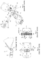
- Fig. 1 shows an embodiment of a total of 50 designated hinge in exploded perspective view.
- the hinge 50 has a first hinge leaf 51 and a second hinge leaf 52.
- the second hinge leaf 52 has a first bearing bush 65a and a spaced second bearing bush 65b.
- a bearing bush 65c of the first hinge leaf 51 is rotatable about a common hinge axis 62.
- An axle tube 53 is rotatably connected to the bearing bush 65c of the first hinge sheet 51 and rotatably supported in the bearing bushes 65a and 65b of the second hinge sheet 52.
- the rotationally fixed connection results from the engagement of an external toothing of the axle tube 53 in an internal toothing of the bearing bush 65c.
- the axle tube 53 is mounted in the bearing bushes 65a, 65b in bearing bushes 66a and 66b.
- the bearing bushes 66a, 66b are easily replaceable.
- the bearing bushes 66a, 66b are made of POM, a plastic with good storage properties. It ensures smooth running and noise minimization. In addition, it compensates for the usual one-sided shrinkage in injection molded parts.
- the bearing bushes 66a, 66b ensure that the bearing bores of the bearing bushes 15a, 15b, which receive the axle tube 13 rotatably, are lined completely round.
- a torsion spring 58 is disposed in the axle tube 53 and provided with a (the in Fig. 1 not visible) end fixed in the axle tube.
- the axle tube 53 has a closed end with a central recess into which the bent end of the torsion spring 58 extends and through which a cylindrical pin 54 c is guided, as in Fig. 1 in an exterior view and in Fig. 3 in a sectional view along the line III-III in Fig. 2 is shown.
- the other end of the torsion spring 58 is rotatably connected to the second hinge leaf 52 by a torque arm 54a.
- a damper housing 56a On an axially opposite side of the axle tube 53 is connected via carrier 56b with the movable part of a damper 56 for the hinge movement.
- the fixed part of the damper 56, a damper housing 56a, is polygonal in cross-section and is in the cross-section corresponding polygonal bore introduced the first bearing bush 65a and rotatably locked therein, without the need for an adhesive bond would be required.
- the torque arm 54a is associated with a retaining ring 68.
- an externally toothed cylindrical pin 54 d is formed on the torque arm, which engages in an internally toothed opening 68 a of the retaining ring 68, and the retaining ring 68 has an externally toothed outer periphery 68 b, which in an internal toothing 69 in the second bearing bush 65 b of the second hinge sheet 52 engages.
- the first and the second bushing 65a, 65b are about the same extent axially over the second hinge leaf 52 as in FIG Fig. 1 to recognize, and are dimensioned so that they in Fig. 1 to the left of the second bushing 65b shown elements of the hinge 50 completely between and in itself, as shown in Fig. 3 in section along the line III-III in Fig. 2 is shown.
- the assembly process of the hinge will be described in more detail below.
- the first bearing bush 65a of the second hinge leaf 52 is closed on its side remote from the second bearing bush 65b, as shown in FIG Fig. 1 can be seen. This is achieved simply by forming the first bushing 65a as a pot-shaped structure on the second hinge sheet 52, whereas the second bushing 65b of the second hinge sheet 52 is integrally molded on the second hinge sheet 52 as a bushing open at both ends in alignment with the first bearing bush 65a.
- the hinge leaves 51, 52 are made in the illustrated embodiment of the hinge 50 according to the invention as injection molded plastic parts.
- the damper 56 has the same structure as the known damper 16 and accordingly has a radial damper vanes rotatable via the cam pins 56b, which is rotatable in a chamber of the viscous damping material filled damper housing 56a, the damper housing being connected to the first bearing bush 65a of the second hinge leaf 52 is positively connected, as already explained above.
- the aforesaid fuse which prevents rotation and axial displacement of the axle tube 53 inserted into the cylindrical cavity co-formed by the three bushings 65a-65c, comprises as a securing element a spring clip 72 passing through two openings 70 in the second bearing bush 65b in a circumferential groove 68b of the retaining ring 68 engages.
- the two bearing sleeves 66a, 66b are inserted into the first and second bearing bushes 65a, 65b, respectively, so that they fit the in Fig. 3 take position shown.
- the first hinge sheet 51 is inserted with its bearing bush 65c between the bearing sleeves 66a, 66b so that it is concentric with the hinge axis 62.
- the damper 56 is inserted into the first bearing bush 65a until it abuts against its inner end, as shown in FIG Fig. 3 is shown.
- the assembly consisting of the axle tube 53 and the torsion spring 58 mounted therein is inserted until two at the end the axle tube existing openings 74 have received the driving pins 56b of the damper 56 in it.
- the torque arm 54 is inserted into the second bearing bush 65b and thereby pushed onto the end of the torsion spring 58 protruding from the axle tube 53.
- a recess is accommodated, which receives the bent end of the torsion spring 58, as shown in FIG Fig. 3 can be seen.
- the cylinder pin 54d has in his outer driving surface two driver openings 74.
- two corresponding driver pins of a rotary tool (not shown) are introduced. With the rotary tool, the torsion spring 58 is twisted so until a desired preload is established.
- a stop buffer 76 ( Fig. 1 ) is pressed against the head of a threaded pin 78 on the first hinge leaf 51, which is fastened with a helicoil 80 in a bore 82 in the second hinge leaf 52.
- the first hinge leaf 51 then occupies a spring-biased position relative to the second hinge leaf 52, which in FIG Fig. 4 shown with dash-dotted lines.
- the first hinge leaf 51 in Fig. 4 at an angle of 75 ° in a position shown in solid lines deflected, in which the lid, not shown, a luggage box, with which the hinge 50 is equipped, in a closed position.
- the further increased by closing the lid torsional force of the torsion spring 58 of the hinge 50 thus acts in the opening direction of the lid.
- the angle of 75 ° is greater than a corresponding angle ⁇ in the known hinge 10 (FIG. Fig. 8 ).
- the assembly of the hinge 50 described above is very simple because it is only necessary in the Fig. 1 to introduce elements shown to the left of the second hinge sheet 52 in the manner described above in the cylindrical cavity of the hinge formed by the bushings 65a-65c, bias the torsion spring 58 as explained and then insert the externally toothed retaining ring 68 in the internally toothed second bearing bush 65b and through the spring clip 72 to secure.
- the hinge 50 has a simpler structure than the hinge 10, since the sleeve 17 and the lid 24 of the known hinge are not needed and thus also eliminates the operations that are required for making connections with epoxy adhesive resin in the known hinge.
Landscapes
- Closing And Opening Devices For Wings, And Checks For Wings (AREA)
- Vehicle Body Suspensions (AREA)
- Pivots And Pivotal Connections (AREA)
Claims (7)
- Charnière pour un compartiment à bagages ou similaire comprenant :une première et une seconde lame de charnière (51, 52), la seconde lame de charnière (52) comprenant un premier coussinet de palier et un second coussinet de palier (65a, 65b) entre lesquels un coussinet de palier (65c) de la première lame de charnière (51) est mobile en rotation autour d'un axe de charnière (62) commun,un tube d'axe (53) qui est relié solidairement en rotation avec le coussinet de palier (65c) de la première lame de charnière (51) et qui est monté mobile en rotation dans les coussinets de palier (65a, 65b) de la seconde lame de charnière (52),un ressort de torsion (58) monté dans le tube d'axe (53) est fixé à ce tube d'axe (53) à l'une de ses extrémités, etun amortisseur (56) du déplacement de la charnière qui est reliée à la seconde lame de charnière (52) et au tube d'axe (53),caractérisée en ce qu'
un support de couple de rotation (54a) relie solidairement en rotation l'autre extrémité du ressort de torsion (58) avec la seconde lame de charnière (52), dans une cavité cylindrique formée en commun au travers des trois coussinets de palier (65a, 65b, 65c) sont introduits successivement, à partir d'une ouverture externe du second coussinet de palier (65b) de la seconde lame de charnière (52), l'amortisseur (56), le tube d'axe (53) renfermant le ressort de torsion (58) et le support de couple de rotation (54a), et, le support de couple de rotation (54a) est bloqué en rotation et en coulissement axial dans le second coussinet de palier (65b) par un dispositif d'arrêt (54d, 68a, 70, 72). - Charnière conforme à la revendication 1,
caractérisée en ce que
le dispositif d'arrêt comporte un élément d'arrêt qui vient en prise par l'intermédiaire d'au moins une ouverture (70) réalisée dans le second coussinet de palier (65b) dans une rainure périphérique (68b) d'une bague de retenue (68) qui est reliée solidairement en rotation avec le support de couple de rotation (54a). - Charnière conforme à la revendication 2,
caractérisée en ce que
l'élément d'arrêt comprend une agrafe élastique (72) qui vient en prise par deux ouvertures (70) réalisées dans le second coussinet de palier (65b) dans la rainure périphérique (68b) de la bague de retenue (68). - Charnière conforme à la revendication 2 ou 3,
caractérisée en ce que
pour permettre la liaison solidaire en rotation du support de couple de rotation (54a) et de la bague de retenue (68) le support de couple de rotation (54a) comprend un goujon cylindrique (54d) muni d'une denture externe qui vient en prise dans une ouverture comportant une denture interne (68a) de la bague de retenue (68), et, la bague de retenue (68) a une périphérie externe équipée d'une denture externe qui vient en prise dans une denture interne (69) du second coussinet de palier (65b) de la seconde lame de palier (52). - Charnière conforme à l'une des revendications 1 à 4,
caractérisée en ce que
le premier coussinet de palier et le second coussinet de palier (65a, 65b) dépassent axialement essentiellement sur la même longueur de la seconde lame de charnière (52). - Charnière conforme à l'une des revendications 1 à 5,
caractérisée en ce que
le premier coussinet de palier (65a) de la seconde lame de charnière (52) est fermé sur sa face située à l'opposé du second coussinet de palier (65b). - Charnière conforme à l'une des revendications 1 à 6,
caractérisée en ce que
l'amortisseur (56) comporte une ailette d'amortissement radial qui est mobile en rotation dans une chambre d'un boîtier d'amortissement (56a) rempli d'un matériau d'amortissement visqueux, le boîtier d'amortissement (56a) étant relié par une liaison par la forme avec le premier coussinet de palier (65a) de la seconde lame de charnière (52).
Applications Claiming Priority (2)
| Application Number | Priority Date | Filing Date | Title |
|---|---|---|---|
| DE202007014471U DE202007014471U1 (de) | 2007-10-16 | 2007-10-16 | Scharnier für eine Gepäckbox o.dgl. |
| PCT/EP2008/063059 WO2009050032A1 (fr) | 2007-10-16 | 2008-09-30 | Charnière pour une boîte porte-bagages ou analogue |
Publications (2)
| Publication Number | Publication Date |
|---|---|
| EP2198103A1 EP2198103A1 (fr) | 2010-06-23 |
| EP2198103B1 true EP2198103B1 (fr) | 2016-05-04 |
Family
ID=40043094
Family Applications (1)
| Application Number | Title | Priority Date | Filing Date |
|---|---|---|---|
| EP08804903.6A Active EP2198103B1 (fr) | 2007-10-16 | 2008-09-30 | Charniere pour une boite porte-bagages ou analogue |
Country Status (6)
| Country | Link |
|---|---|
| US (1) | US8266764B2 (fr) |
| EP (1) | EP2198103B1 (fr) |
| CN (1) | CN101688415B (fr) |
| CA (1) | CA2692700C (fr) |
| DE (1) | DE202007014471U1 (fr) |
| WO (1) | WO2009050032A1 (fr) |
Cited By (1)
| Publication number | Priority date | Publication date | Assignee | Title |
|---|---|---|---|---|
| EP4420980A1 (fr) | 2023-02-23 | 2024-08-28 | Airbus Operations GmbH | Ensemble charnière, ainsi que compartiment de stockage ou monument pour installation dans une cabine d'aéronef ou d'engin spatial |
Families Citing this family (12)
| Publication number | Priority date | Publication date | Assignee | Title |
|---|---|---|---|---|
| DE202010009919U1 (de) * | 2010-07-06 | 2010-09-30 | S-Fasteners Gmbh | Scharnier mit Torsions-Spiral-Feder, deren Spannung einstellbar ist |
| CN203022493U (zh) * | 2011-01-14 | 2013-06-26 | 漳州威迪亚卫浴有限公司 | 一种改良的阻尼结构 |
| EP2670935A4 (fr) * | 2011-02-04 | 2016-11-02 | D&D Group Pty Ltd | Charnière |
| US8745820B2 (en) * | 2011-09-30 | 2014-06-10 | Itt Manufacturing Enterprises Llc | Rotary hinge with adjustable damping assembly |
| CN103967367B (zh) * | 2013-01-24 | 2016-08-17 | 陈政 | 一种缓冲门折页 |
| US9348372B2 (en) * | 2014-06-13 | 2016-05-24 | Apple Inc. | Friction hinge with embedded counterbalance |
| CN105033424A (zh) * | 2015-06-01 | 2015-11-11 | 孟书芳 | 一种二氧化碳气保焊机焊箱盖闭组件 |
| US10047557B2 (en) * | 2017-01-18 | 2018-08-14 | Macauto Industrial Co., Ltd. | Side plate pressing device for a vehicle curtain |
| CN107514199B (zh) * | 2017-09-12 | 2024-11-22 | 浙江木子机电有限公司 | 一种多功能复合型凸轮结构自动闭门合页 |
| CN107386847B (zh) * | 2017-09-15 | 2023-07-07 | 深圳市百代亚星科技有限公司 | 自复位式合金卡扣 |
| DE202017106060U1 (de) * | 2017-10-06 | 2017-12-01 | S-Fasteners Gmbh | Scharnier mit spannbarem Federelement |
| EP4656828A1 (fr) | 2024-05-27 | 2025-12-03 | SFS Group International AG | Charnière pour compartiment à bagages |
Family Cites Families (16)
| Publication number | Priority date | Publication date | Assignee | Title |
|---|---|---|---|---|
| US3903567A (en) * | 1974-09-24 | 1975-09-09 | Stanley Works | Two knuckle hinges |
| JPS5725969Y2 (fr) * | 1977-10-08 | 1982-06-05 | ||
| US4485522A (en) * | 1982-08-31 | 1984-12-04 | Chen Youn Long | Door-closing hinge having a spring and pin mechanism |
| ES295448Y (es) * | 1986-06-25 | 1987-09-01 | Zeljko Bebek Vuksic | Bisagra de resorte con amortiguador, perfeccionada |
| US5222260A (en) * | 1991-07-01 | 1993-06-29 | Piper Dean E | Toilet cover closure device |
| US5572768A (en) | 1994-04-13 | 1996-11-12 | Enidine Incorporated | Door closer |
| US5715574A (en) * | 1996-03-18 | 1998-02-10 | Delair Group Llc | Adjustable self-closing hinge assembly |
| DE29808910U1 (de) | 1998-05-16 | 1998-08-06 | Schwarz Verbindungs-Systeme GmbH, 75382 Althengstett | Scharnier mit Bewegungsdämpfung |
| WO2000061903A1 (fr) * | 1999-03-19 | 2000-10-19 | Doorsoft Co.,Ltd. | Dispositif vertical de fermeture de porte |
| US6182301B1 (en) * | 1999-08-16 | 2001-02-06 | Creative Innovation, Inc. | Apparatus and method for automatically pivoting a first member relative to a second member |
| GB2355044B (en) * | 1999-10-08 | 2003-07-02 | Nokia Mobile Phones Ltd | Hinge |
| DE20021956U1 (de) | 2000-12-23 | 2001-03-15 | Schwarz Verbindungs-Systeme GmbH, 75382 Althengstett | Federkraftbeaufschlagtes Scharnier und Dämpfungsanordnung, insbesondere für ein federkraftbeaufschlagtes Scharnier |
| JP4014814B2 (ja) | 2001-03-30 | 2007-11-28 | スガツネ工業株式会社 | ヒンジ装置 |
| US6922869B2 (en) * | 2002-01-25 | 2005-08-02 | Illinois Tool Works Inc. | Damper apparatus |
| JP4180892B2 (ja) * | 2002-11-25 | 2008-11-12 | スガツネ工業株式会社 | キャッチ機能付きヒンジ |
| DE20308234U1 (de) | 2003-05-27 | 2003-08-21 | Schwarz Verbindungssysteme GmbH, 75382 Althengstett | Anordnung zur Aufnahme eines lösbar verriegelbaren Einschub-Elementes |
-
2007
- 2007-10-16 DE DE202007014471U patent/DE202007014471U1/de not_active Expired - Lifetime
-
2008
- 2008-09-30 CN CN200880022810XA patent/CN101688415B/zh not_active Expired - Fee Related
- 2008-09-30 CA CA2692700A patent/CA2692700C/fr not_active Expired - Fee Related
- 2008-09-30 EP EP08804903.6A patent/EP2198103B1/fr active Active
- 2008-09-30 WO PCT/EP2008/063059 patent/WO2009050032A1/fr not_active Ceased
- 2008-09-30 US US12/674,046 patent/US8266764B2/en active Active
Cited By (2)
| Publication number | Priority date | Publication date | Assignee | Title |
|---|---|---|---|---|
| EP4420980A1 (fr) | 2023-02-23 | 2024-08-28 | Airbus Operations GmbH | Ensemble charnière, ainsi que compartiment de stockage ou monument pour installation dans une cabine d'aéronef ou d'engin spatial |
| WO2024175784A1 (fr) | 2023-02-23 | 2024-08-29 | Airbus Operations Gmbh | Ensemble charnière pour installation dans une cabine d'aéronef ou d'engin spatial |
Also Published As
| Publication number | Publication date |
|---|---|
| EP2198103A1 (fr) | 2010-06-23 |
| US8266764B2 (en) | 2012-09-18 |
| US20110185536A1 (en) | 2011-08-04 |
| CN101688415B (zh) | 2013-03-27 |
| CA2692700C (fr) | 2014-12-16 |
| WO2009050032A1 (fr) | 2009-04-23 |
| DE202007014471U1 (de) | 2009-03-12 |
| CN101688415A (zh) | 2010-03-31 |
| CA2692700A1 (fr) | 2009-04-23 |
Similar Documents
| Publication | Publication Date | Title |
|---|---|---|
| EP2198103B1 (fr) | Charniere pour une boite porte-bagages ou analogue | |
| DE112006003781B4 (de) | Einbaubereites Gedämpftes Scharniermodul | |
| DE69015425T2 (de) | Dämpfer mit viskoser Flüssigkeit für Klapptüre. | |
| DE3610284C2 (fr) | ||
| DE602005001818T2 (de) | Kupplungsmechanismus für Schlösser | |
| EP1217158A2 (fr) | Charnière sollicitée par un ressort et un dispositif amortisseur, en particulier pour une charnière sollicitée par un ressort | |
| EP2231974A1 (fr) | Paumelle, en particulier pour des portes battantes en verre | |
| DE10013726A1 (de) | Klappenscharnier | |
| EP1068419B1 (fr) | Element d'arret de portiere integre a une charniere de portiere | |
| DE2933555C2 (de) | Türscharnier mit Schließeinrichtung | |
| DE19823188C2 (de) | Kraftfahrzeugtürverschluß | |
| DE2435833A1 (de) | Espagnolette-schloss | |
| DE102020126201B3 (de) | Friktionsscharnier | |
| DE102008049740B4 (de) | Höhenverstellbares Band | |
| EP0748908B1 (fr) | Cylindre de serrure | |
| DE29808910U1 (de) | Scharnier mit Bewegungsdämpfung | |
| EP0713947B1 (fr) | Dispositif pour la manoeuvre de rotation sur la commande de mise en action d'une fenêtre, d'une porte ou similaire | |
| EP1173649A1 (fr) | Paumelle pour portes, fenetres et analogues | |
| EP0713946A2 (fr) | Serrure de meuble ou fermeture | |
| WO2004085780A1 (fr) | Penture, notamment pour portes de douche et/ou portes en verre | |
| DE102004041723B3 (de) | Scharnierschalter | |
| EP0760890B1 (fr) | Charniere en plusieurs parties | |
| DE2160519A1 (de) | Einstellbare zapfenbandanordnung | |
| WO1995034764A1 (fr) | Dispositif d'accouplement | |
| DE2923834C2 (fr) |
Legal Events
| Date | Code | Title | Description |
|---|---|---|---|
| PUAI | Public reference made under article 153(3) epc to a published international application that has entered the european phase |
Free format text: ORIGINAL CODE: 0009012 |
|
| 17P | Request for examination filed |
Effective date: 20100112 |
|
| AK | Designated contracting states |
Kind code of ref document: A1 Designated state(s): AT BE BG CH CY CZ DE DK EE ES FI FR GB GR HR HU IE IS IT LI LT LU LV MC MT NL NO PL PT RO SE SI SK TR |
|
| AX | Request for extension of the european patent |
Extension state: AL BA MK RS |
|
| DAX | Request for extension of the european patent (deleted) | ||
| GRAP | Despatch of communication of intention to grant a patent |
Free format text: ORIGINAL CODE: EPIDOSNIGR1 |
|
| INTG | Intention to grant announced |
Effective date: 20160108 |
|
| GRAS | Grant fee paid |
Free format text: ORIGINAL CODE: EPIDOSNIGR3 |
|
| GRAA | (expected) grant |
Free format text: ORIGINAL CODE: 0009210 |
|
| AK | Designated contracting states |
Kind code of ref document: B1 Designated state(s): AT BE BG CH CY CZ DE DK EE ES FI FR GB GR HR HU IE IS IT LI LT LU LV MC MT NL NO PL PT RO SE SI SK TR |
|
| REG | Reference to a national code |
Ref country code: GB Ref legal event code: FG4D Free format text: NOT ENGLISH |
|
| REG | Reference to a national code |
Ref country code: CH Ref legal event code: EP |
|
| REG | Reference to a national code |
Ref country code: AT Ref legal event code: REF Ref document number: 797069 Country of ref document: AT Kind code of ref document: T Effective date: 20160515 |
|
| REG | Reference to a national code |
Ref country code: IE Ref legal event code: FG4D Free format text: LANGUAGE OF EP DOCUMENT: GERMAN |
|
| REG | Reference to a national code |
Ref country code: DE Ref legal event code: R096 Ref document number: 502008014172 Country of ref document: DE |
|
| REG | Reference to a national code |
Ref country code: NL Ref legal event code: MP Effective date: 20160504 |
|
| REG | Reference to a national code |
Ref country code: LT Ref legal event code: MG4D |
|
| PG25 | Lapsed in a contracting state [announced via postgrant information from national office to epo] |
Ref country code: NL Free format text: LAPSE BECAUSE OF FAILURE TO SUBMIT A TRANSLATION OF THE DESCRIPTION OR TO PAY THE FEE WITHIN THE PRESCRIBED TIME-LIMIT Effective date: 20160504 Ref country code: FI Free format text: LAPSE BECAUSE OF FAILURE TO SUBMIT A TRANSLATION OF THE DESCRIPTION OR TO PAY THE FEE WITHIN THE PRESCRIBED TIME-LIMIT Effective date: 20160504 Ref country code: NO Free format text: LAPSE BECAUSE OF FAILURE TO SUBMIT A TRANSLATION OF THE DESCRIPTION OR TO PAY THE FEE WITHIN THE PRESCRIBED TIME-LIMIT Effective date: 20160804 Ref country code: LT Free format text: LAPSE BECAUSE OF FAILURE TO SUBMIT A TRANSLATION OF THE DESCRIPTION OR TO PAY THE FEE WITHIN THE PRESCRIBED TIME-LIMIT Effective date: 20160504 |
|
| PG25 | Lapsed in a contracting state [announced via postgrant information from national office to epo] |
Ref country code: PT Free format text: LAPSE BECAUSE OF FAILURE TO SUBMIT A TRANSLATION OF THE DESCRIPTION OR TO PAY THE FEE WITHIN THE PRESCRIBED TIME-LIMIT Effective date: 20160905 Ref country code: HR Free format text: LAPSE BECAUSE OF FAILURE TO SUBMIT A TRANSLATION OF THE DESCRIPTION OR TO PAY THE FEE WITHIN THE PRESCRIBED TIME-LIMIT Effective date: 20160504 Ref country code: GR Free format text: LAPSE BECAUSE OF FAILURE TO SUBMIT A TRANSLATION OF THE DESCRIPTION OR TO PAY THE FEE WITHIN THE PRESCRIBED TIME-LIMIT Effective date: 20160805 Ref country code: LV Free format text: LAPSE BECAUSE OF FAILURE TO SUBMIT A TRANSLATION OF THE DESCRIPTION OR TO PAY THE FEE WITHIN THE PRESCRIBED TIME-LIMIT Effective date: 20160504 Ref country code: SE Free format text: LAPSE BECAUSE OF FAILURE TO SUBMIT A TRANSLATION OF THE DESCRIPTION OR TO PAY THE FEE WITHIN THE PRESCRIBED TIME-LIMIT Effective date: 20160504 Ref country code: ES Free format text: LAPSE BECAUSE OF FAILURE TO SUBMIT A TRANSLATION OF THE DESCRIPTION OR TO PAY THE FEE WITHIN THE PRESCRIBED TIME-LIMIT Effective date: 20160504 |
|
| PG25 | Lapsed in a contracting state [announced via postgrant information from national office to epo] |
Ref country code: IT Free format text: LAPSE BECAUSE OF FAILURE TO SUBMIT A TRANSLATION OF THE DESCRIPTION OR TO PAY THE FEE WITHIN THE PRESCRIBED TIME-LIMIT Effective date: 20160504 |
|
| PG25 | Lapsed in a contracting state [announced via postgrant information from national office to epo] |
Ref country code: EE Free format text: LAPSE BECAUSE OF FAILURE TO SUBMIT A TRANSLATION OF THE DESCRIPTION OR TO PAY THE FEE WITHIN THE PRESCRIBED TIME-LIMIT Effective date: 20160504 Ref country code: SK Free format text: LAPSE BECAUSE OF FAILURE TO SUBMIT A TRANSLATION OF THE DESCRIPTION OR TO PAY THE FEE WITHIN THE PRESCRIBED TIME-LIMIT Effective date: 20160504 Ref country code: DK Free format text: LAPSE BECAUSE OF FAILURE TO SUBMIT A TRANSLATION OF THE DESCRIPTION OR TO PAY THE FEE WITHIN THE PRESCRIBED TIME-LIMIT Effective date: 20160504 Ref country code: RO Free format text: LAPSE BECAUSE OF FAILURE TO SUBMIT A TRANSLATION OF THE DESCRIPTION OR TO PAY THE FEE WITHIN THE PRESCRIBED TIME-LIMIT Effective date: 20160504 Ref country code: CZ Free format text: LAPSE BECAUSE OF FAILURE TO SUBMIT A TRANSLATION OF THE DESCRIPTION OR TO PAY THE FEE WITHIN THE PRESCRIBED TIME-LIMIT Effective date: 20160504 |
|
| REG | Reference to a national code |
Ref country code: DE Ref legal event code: R097 Ref document number: 502008014172 Country of ref document: DE |
|
| PG25 | Lapsed in a contracting state [announced via postgrant information from national office to epo] |
Ref country code: PL Free format text: LAPSE BECAUSE OF FAILURE TO SUBMIT A TRANSLATION OF THE DESCRIPTION OR TO PAY THE FEE WITHIN THE PRESCRIBED TIME-LIMIT Effective date: 20160504 Ref country code: BE Free format text: LAPSE BECAUSE OF NON-PAYMENT OF DUE FEES Effective date: 20160930 |
|
| PLBE | No opposition filed within time limit |
Free format text: ORIGINAL CODE: 0009261 |
|
| STAA | Information on the status of an ep patent application or granted ep patent |
Free format text: STATUS: NO OPPOSITION FILED WITHIN TIME LIMIT |
|
| 26N | No opposition filed |
Effective date: 20170207 |
|
| PG25 | Lapsed in a contracting state [announced via postgrant information from national office to epo] |
Ref country code: MC Free format text: LAPSE BECAUSE OF FAILURE TO SUBMIT A TRANSLATION OF THE DESCRIPTION OR TO PAY THE FEE WITHIN THE PRESCRIBED TIME-LIMIT Effective date: 20160504 |
|
| REG | Reference to a national code |
Ref country code: CH Ref legal event code: PL |
|
| GBPC | Gb: european patent ceased through non-payment of renewal fee |
Effective date: 20160930 |
|
| PG25 | Lapsed in a contracting state [announced via postgrant information from national office to epo] |
Ref country code: SI Free format text: LAPSE BECAUSE OF FAILURE TO SUBMIT A TRANSLATION OF THE DESCRIPTION OR TO PAY THE FEE WITHIN THE PRESCRIBED TIME-LIMIT Effective date: 20160504 |
|
| REG | Reference to a national code |
Ref country code: IE Ref legal event code: MM4A |
|
| REG | Reference to a national code |
Ref country code: FR Ref legal event code: ST Effective date: 20170531 |
|
| PG25 | Lapsed in a contracting state [announced via postgrant information from national office to epo] |
Ref country code: LI Free format text: LAPSE BECAUSE OF NON-PAYMENT OF DUE FEES Effective date: 20160930 Ref country code: CH Free format text: LAPSE BECAUSE OF NON-PAYMENT OF DUE FEES Effective date: 20160930 Ref country code: IE Free format text: LAPSE BECAUSE OF NON-PAYMENT OF DUE FEES Effective date: 20160930 Ref country code: FR Free format text: LAPSE BECAUSE OF NON-PAYMENT OF DUE FEES Effective date: 20160930 Ref country code: GB Free format text: LAPSE BECAUSE OF NON-PAYMENT OF DUE FEES Effective date: 20160930 |
|
| PG25 | Lapsed in a contracting state [announced via postgrant information from national office to epo] |
Ref country code: LU Free format text: LAPSE BECAUSE OF NON-PAYMENT OF DUE FEES Effective date: 20160930 |
|
| REG | Reference to a national code |
Ref country code: AT Ref legal event code: MM01 Ref document number: 797069 Country of ref document: AT Kind code of ref document: T Effective date: 20160930 |
|
| REG | Reference to a national code |
Ref country code: BE Ref legal event code: MM Effective date: 20160930 |
|
| PG25 | Lapsed in a contracting state [announced via postgrant information from national office to epo] |
Ref country code: AT Free format text: LAPSE BECAUSE OF NON-PAYMENT OF DUE FEES Effective date: 20160930 |
|
| PG25 | Lapsed in a contracting state [announced via postgrant information from national office to epo] |
Ref country code: CY Free format text: LAPSE BECAUSE OF FAILURE TO SUBMIT A TRANSLATION OF THE DESCRIPTION OR TO PAY THE FEE WITHIN THE PRESCRIBED TIME-LIMIT Effective date: 20160504 Ref country code: HU Free format text: LAPSE BECAUSE OF FAILURE TO SUBMIT A TRANSLATION OF THE DESCRIPTION OR TO PAY THE FEE WITHIN THE PRESCRIBED TIME-LIMIT; INVALID AB INITIO Effective date: 20080930 |
|
| PG25 | Lapsed in a contracting state [announced via postgrant information from national office to epo] |
Ref country code: IS Free format text: LAPSE BECAUSE OF FAILURE TO SUBMIT A TRANSLATION OF THE DESCRIPTION OR TO PAY THE FEE WITHIN THE PRESCRIBED TIME-LIMIT Effective date: 20160504 Ref country code: MT Free format text: LAPSE BECAUSE OF FAILURE TO SUBMIT A TRANSLATION OF THE DESCRIPTION OR TO PAY THE FEE WITHIN THE PRESCRIBED TIME-LIMIT Effective date: 20160504 Ref country code: TR Free format text: LAPSE BECAUSE OF FAILURE TO SUBMIT A TRANSLATION OF THE DESCRIPTION OR TO PAY THE FEE WITHIN THE PRESCRIBED TIME-LIMIT Effective date: 20160504 |
|
| PG25 | Lapsed in a contracting state [announced via postgrant information from national office to epo] |
Ref country code: BG Free format text: LAPSE BECAUSE OF FAILURE TO SUBMIT A TRANSLATION OF THE DESCRIPTION OR TO PAY THE FEE WITHIN THE PRESCRIBED TIME-LIMIT Effective date: 20160504 |
|
| P01 | Opt-out of the competence of the unified patent court (upc) registered |
Effective date: 20230622 |
|
| PGFP | Annual fee paid to national office [announced via postgrant information from national office to epo] |
Ref country code: DE Payment date: 20250919 Year of fee payment: 18 |
|
| REG | Reference to a national code |
Ref country code: DE Ref legal event code: R082 Ref document number: 502008014172 Country of ref document: DE |