EP2198136B1 - Verfahren zur diagnostizierung des status eines katalytischen umrichters des abgassystems eines kraftfahrzeugmotors - Google Patents
Verfahren zur diagnostizierung des status eines katalytischen umrichters des abgassystems eines kraftfahrzeugmotors Download PDFInfo
- Publication number
- EP2198136B1 EP2198136B1 EP08841862A EP08841862A EP2198136B1 EP 2198136 B1 EP2198136 B1 EP 2198136B1 EP 08841862 A EP08841862 A EP 08841862A EP 08841862 A EP08841862 A EP 08841862A EP 2198136 B1 EP2198136 B1 EP 2198136B1
- Authority
- EP
- European Patent Office
- Prior art keywords
- converter
- catalytic converter
- temperature
- concentration
- condition
- Prior art date
- Legal status (The legal status is an assumption and is not a legal conclusion. Google has not performed a legal analysis and makes no representation as to the accuracy of the status listed.)
- Not-in-force
Links
Images
Classifications
-
- F—MECHANICAL ENGINEERING; LIGHTING; HEATING; WEAPONS; BLASTING
- F01—MACHINES OR ENGINES IN GENERAL; ENGINE PLANTS IN GENERAL; STEAM ENGINES
- F01N—GAS-FLOW SILENCERS OR EXHAUST APPARATUS FOR MACHINES OR ENGINES IN GENERAL; GAS-FLOW SILENCERS OR EXHAUST APPARATUS FOR INTERNAL-COMBUSTION ENGINES
- F01N11/00—Monitoring or diagnostic devices for exhaust-gas treatment apparatus
-
- F—MECHANICAL ENGINEERING; LIGHTING; HEATING; WEAPONS; BLASTING
- F01—MACHINES OR ENGINES IN GENERAL; ENGINE PLANTS IN GENERAL; STEAM ENGINES
- F01N—GAS-FLOW SILENCERS OR EXHAUST APPARATUS FOR MACHINES OR ENGINES IN GENERAL; GAS-FLOW SILENCERS OR EXHAUST APPARATUS FOR INTERNAL-COMBUSTION ENGINES
- F01N11/00—Monitoring or diagnostic devices for exhaust-gas treatment apparatus
- F01N11/002—Monitoring or diagnostic devices for exhaust-gas treatment apparatus the diagnostic devices measuring or estimating temperature or pressure in, or downstream of the exhaust apparatus
-
- F—MECHANICAL ENGINEERING; LIGHTING; HEATING; WEAPONS; BLASTING
- F01—MACHINES OR ENGINES IN GENERAL; ENGINE PLANTS IN GENERAL; STEAM ENGINES
- F01N—GAS-FLOW SILENCERS OR EXHAUST APPARATUS FOR MACHINES OR ENGINES IN GENERAL; GAS-FLOW SILENCERS OR EXHAUST APPARATUS FOR INTERNAL-COMBUSTION ENGINES
- F01N2550/00—Monitoring or diagnosing the deterioration of exhaust systems
- F01N2550/02—Catalytic activity of catalytic converters
-
- Y—GENERAL TAGGING OF NEW TECHNOLOGICAL DEVELOPMENTS; GENERAL TAGGING OF CROSS-SECTIONAL TECHNOLOGIES SPANNING OVER SEVERAL SECTIONS OF THE IPC; TECHNICAL SUBJECTS COVERED BY FORMER USPC CROSS-REFERENCE ART COLLECTIONS [XRACs] AND DIGESTS
- Y02—TECHNOLOGIES OR APPLICATIONS FOR MITIGATION OR ADAPTATION AGAINST CLIMATE CHANGE
- Y02T—CLIMATE CHANGE MITIGATION TECHNOLOGIES RELATED TO TRANSPORTATION
- Y02T10/00—Road transport of goods or passengers
- Y02T10/10—Internal combustion engine [ICE] based vehicles
- Y02T10/40—Engine management systems
Definitions
- the present invention relates to a method for diagnosing the state of a catalytic converter of an exhaust system of an engine of a motor vehicle. It also relates to a diagnostic device for implementing such a diagnostic method.
- Emission thresholds are set by regulations.
- an OBD regulation for On-Board Diagnostics
- the regulations impose, by the definition of emission thresholds of pollutants, functional diagnoses of major components of the pollution control system and in particular the oxidation catalyst.
- the objective is therefore to be able to more finely diagnose a failure of a catalytic converter in terms of loss of conversion efficiency.
- Patent is known US5,182,907 a method for diagnosing a failure of a three-way catalyst in which an upstream sensor is used to determine the hydrocarbon concentration upstream of the catalyst, a downstream sensor for determining the hydrocarbon concentration downstream of the catalyst and a temperature probe for determine the temperature of the catalyst.
- an upstream sensor is used to determine the hydrocarbon concentration upstream of the catalyst
- a downstream sensor for determining the hydrocarbon concentration downstream of the catalyst
- a temperature probe for determine the temperature of the catalyst.
- Document is also known DE 197 58 154 a method for diagnosing a failure of a three-way catalytic converter in which an upstream sensor and a sensor in particular are used; downstream of the catalytic converter to determine its performance.
- Other parameters are used in this complex process to determine the energy supplied to the converter between a cold start time and the moment when the efficiency of the converter becomes greater than 50%.
- Such a method is complex, it requires making slabs of estimation calculations using many parameters.
- it may not be usable if regulations become more severe.
- the method can be implemented only in special situations: it requires starting with a cold start. Thus, its frequency of implementation may be incompatible with the new standards.
- Document is known DE 198 11 574 a method for diagnosing a catalyst in which two pollutant sensors are used upstream and downstream of the catalyst.
- the object of the invention is to provide a method for diagnosing the state of a catalytic converter that obviates the disadvantages identified above and improves the diagnostic methods known from the prior art.
- the invention proposes a method that is simple to implement, requires few means and makes it possible to reliably and robustly determine the state of a catalytic converter. It also makes it possible to considerably reduce the cost of the technical definition, to minimize the size of the converter monitoring strategy and to determine a defective state of a converter relative to a very low regulatory threshold, which can not be done. the methods known from the prior art. Finally, it makes it possible to dispense with dedicated temperature sensors.
- the method for diagnosing the state of a catalytic converter of an exhaust system of an engine of a motor vehicle comprises a step for estimating whether the temperature of the catalytic converter is within a temperature range in which a converter in good condition is initiated and in which a converter in poor condition is not initiated and, when this is the case, a step of measuring a concentration of one pollutant downstream of the catalytic converter to determine the state of the converter and a step of analyzing the concentration value of the pollutant to deduce that the catalytic converter is in poor condition if the concentration value is above a threshold and to deduce that the catalytic converter is in good condition if the concentration value is below the threshold.
- one or more pollutant concentration measurements are used downstream of the catalytic converter to determine the state of the converter.
- the step of estimating whether the temperature of the catalytic converter is within a temperature range may include an exhaust gas temperature measurement.
- the step of estimating whether the temperature of the catalytic converter is within a temperature range may include a temperature measurement of the engine coolant and at least one measurement of another engine condition parameter.
- the step of measuring a pollutant concentration can be a step of measuring a hydrocarbon concentration.
- a device for diagnosing the state of a catalytic converter comprises hardware and software means for implementing the method defined above.
- the diagnostic device may comprise a sensor for measuring the concentration of a pollutant downstream of the catalytic converter.
- the diagnostic device may comprise a temperature measuring sensor also used to perform a function other than the measuring condition determining function in which the step of measuring the concentration of the pollutant downstream of the catalytic converter is carried out.
- a motor vehicle comprises a diagnostic device defined above.
- the diagnostic method according to the invention applies in particular to an oxidation catalyst type converter ensuring the oxidation of unburned hydrocarbons and carbon monoxide in a post-processing system of a compression ignition engine.
- the principle of the method according to the invention is based on the close link that exists between the aging of the converter and its efficiency under particular operating conditions. Indeed, the starting temperature of the converter and the hydrocarbon conversion efficiency are two closely related phenomena. In addition, aging of the oxidation catalyst has a direct influence on the initiation temperature by shifting it to high temperatures and thus on the treatment of pollutants released by the engine, including hydrocarbons and carbon monoxide.
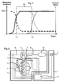
- figure 1 shows, as a function of temperature, in continuous lines, the conversion efficiency of two converters.
- the conversion efficiency of a converter in good condition is shown in bold line and conversion efficiency of a used converter is shown in fine line.
- the same efficiency of the two converters is obtained with significantly different temperature values, this temperature being significantly higher for a used converter than for a converter in good condition.
- the levels of the signals received from a hydrocarbon concentration measurement sensor downstream of the two converters mentioned above are represented in the same figure.
- dashed lines is represented the level of the signal downstream of a converter in good condition and, in fine dashed lines, is represented the level of the signal downstream of a used converter.
- a temperature range (bounded by two vertical lines in phantom lines) appears in which a converter in good condition is operational and in which a used converter is not operational.
- a diagnostic device 1 making it possible to implement a measurement method according to the invention is represented in FIG. figure 2 in situation on an internal combustion engine 2 of a motor vehicle.
- the engine 2 mainly comprises a cylinder block 3 fed by intake lines 4 and 6 and a compressor of a turbocharger 5.
- the exhaust gases are discharged via an exhaust line 8 after passing through a turbine of turbocharger.
- the exhaust line comprises a catalytic converter 10 comprising in particular an oxidation converter. It further comprises various sensors connected to an electronic computer 12 for controlling its operation.
- the diagnostic device 1 comprises a pollutant concentration sensor 11 disposed on the exhaust line downstream of the catalytic converter 10. This sensor is connected to the electronic computer 12. This connection enables the computer to collect the measured pollutant concentration values. by the sensor.
- the sensor is preferably a hydrocarbon concentration sensor.
- the diagnostic device 1 also comprises one or more other sensors making it possible to determine when the measurement of hydrocarbon concentration by the sensor 11 must be carried out and thus make it possible to diagnose the state of the catalytic converter. This or these other sensors are also connected to the computer 12. However, they are preferably used to perform other functions that monitoring the state of the converter and are not dedicated to this monitoring function. Thus, the diagnostic method according to the invention requires only a sensor downstream of the converter and an electronic computer 12 having access to engine parameters used for other functions.
- the computer comprises at least one software module for governing the operation of the diagnostic device according to the diagnostic method object of the invention.
- the diagnostic device also includes means (not shown) to indicate that the converter is in poor condition or is worn. These means may for example include a witness on the dashboard of the vehicle.
- a hydrocarbon concentration sensor downstream of the catalytic converter makes it possible to detect and measure a low converter failure. If the emission of pollutants exceeds a threshold set by the regulations, however weak, it will be due to a converter failure and it will be possible to detect this failure.
- the catalytic converter may especially be a diesel oxidation catalyst of any type of material or a catalytic particle filter.
- a diagnostic device uses information from an exhaust temperature sensor 9 of the type before turbine temperature sensor to have a thermal information close to the converter to be diagnosed.
- a diagnostic device uses information from a temperature sensor of a particulate filter system making it possible to have thermal information close to the converter to be diagnosed.
- this uses information from a coolant temperature sensor accumulated with conventional engine information such as, for example, the engine speed and / or the load, in order to approximately determine the engine temperature. converter to diagnose.
- the method for determining the state of a converter comprises a method of setting parameters and parameter values and a method of diagnosis.
- the method for defining parameters and parameter values comprises, for example, the series of steps 110 to 130 described below and serves to identify the phases of engine operation making it possible to ensure reliable decision-making on the state. of the converter.
- the terminals T1, T2 of a temperature range are determined in which a converter judged to be in good condition has a high conversion efficiency, for example greater than 80%, and in which a converter considered to be in poor condition. has a low conversion efficiency, for example less than 20%.
- This determination is for example made by statistical means after measurements performed on a population of converters in good condition and a population of converters in poor condition.
- sets of engine operating parameters are determined, in particular thermal parameters at the level of the coolant and / or thermal parameters on the exhaust line and / or engine speed parameters and / or engine load parameters and / or time parameters, corresponding to the temperature range defined in step 110.
- means are determined for detecting the periods during which the temperature of the converter will be within the temperature range defined in step 110.
- This step can be performed for example by series of experimental processes or by simulation.
- step 130 one chooses the parameters which will be monitored and used to identify the periods in which the temperature of the converter is between the terminals T1 and T2.
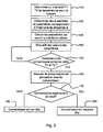
- the diagnostic method used to analyze and determine the state of the converter is implemented.
- One embodiment of this diagnostic method comprises the following steps described below.
- a first step 140 the electronic computer collects vehicle operating parameter values and in particular the operating parameters chosen in step 130.
- a second step 150 the electronic calculator estimates using an algorithm and the values collected above, if the temperature of the converter is between terminals T1 and T2. Thus, it is ensured that one is in the temperature zone in which a converter in good condition is started and in which a converter in poor condition is not initiated (and therefore does not yet treat hydrocarbons).
- step 160 in which the computer collects or takes into account the pollutant concentration value supplied by the sensor 11 downstream of the converter.
- the pollutant concentration value is analyzed, for example, by comparison with a threshold.
- this value is greater than the threshold, it is deduced in a step 180 that the catalytic converter is in poor condition. Means can then be implemented to signal this bad state.
- the diagnostic method according to the invention it is possible to distinguish a converter in good condition which is primed and which processes the hydrocarbons discharged by the engine (by a lack of detection of hydrocarbons downstream of the converter), a a converter in poor condition which is not primed and which does not treat the oil discharged by the engine (by a hydrocarbon detection downstream of the converter), this distinction being made exclusively in the temperature range mentioned above.
- the diagnostic method can be implemented at a standstill, with the engine running, in a maintenance operation, an after-sales diagnostic tool being provided for exploiting the signals emitted by the hydrocarbon sensor 11.
- the method according to the invention has various advantages. It makes it possible to detect converter states that are not detectable by means known from the prior art. In addition, this detection can be made accurately, reliably and robustly.
- the diagnostic method according to the invention makes it possible to dispense with sensors usually dedicated to the monitoring of the catalytic converter.
- sensors usually dedicated to the monitoring of the catalytic converter In particular, one can dispense with any temperature sensor or any wealth sensor dedicated to the sole monitoring of the converter in the state of the art.
- the diagnostic method according to the invention can be performed continuously on all phases of operation of the engine with a guaranteed and robust result.
Landscapes
- Engineering & Computer Science (AREA)
- Chemical & Material Sciences (AREA)
- Chemical Kinetics & Catalysis (AREA)
- Combustion & Propulsion (AREA)
- Mechanical Engineering (AREA)
- General Engineering & Computer Science (AREA)
- Exhaust Gas After Treatment (AREA)
Claims (9)
- Verfahren zur Diagnose des Zustands eines katalytischen Konverters (10) eines Auspuffsystems eines Motors (2) eines Kraftfahrzeugs, dadurch gekennzeichnet, dass es einen Schritt des Schätzens, ob die Temperatur des katalytischen Konverters in einem Temperaturbereich (T1, T2) liegt, in dem ein Konverter in gutem Zustand aktiviert wird und in dem ein Konverter in schlechtem Zustand nicht aktiviert wird, und, wenn dies der Fall ist, einen Schritt des Messens einer Konzentration eines Schadstoffs hinter dem katalytischen Konverter, um den Zustand des Konverters zu bestimmen, und einen Schritt der Analyse des Konzentrationswerts des Schadstoffs enthält, um daraus abzuleiten, dass der katalytische Konverter in schlechtem Zustand ist, wenn der Konzentrationswert über einer Schwelle liegt, und abzuleiten, dass der katalytische Konverter in gutem Zustand ist, wenn der Konzentrationswert unter der Schwelle liegt.
- Diagnoseverfahren nach Anspruch 1, dadurch gekennzeichnet, dass ausschließlich eine oder mehrere Schadstoff-Konzentrationsmessungen hinter dem katalytischen Konverter verwendet werden, um den Zustand des Konverters zu bestimmen.
- Diagnoseverfahren nach einem der Ansprüche 1 oder 2, dadurch gekennzeichnet, dass der Schritt des Schätzens, ob die Temperatur des katalytischen Konverters in einem Temperaturbereich (T1, T2) liegt, eine Temperaturmessung der Abgase enthält.
- Diagnoseverfahren nach einem der Ansprüche 1 oder 2, dadurch gekennzeichnet, dass der Schritt des Schätzens, ob die Temperatur des katalytischen Konverters in einem Temperaturbereich (T1, T2) liegt, eine Temperaturmessung der Kühlflüssigkeit des Motors und mindestens eine Messung eines anderen Zustandsparameters des Motors enthält.
- Diagnoseverfahren nach einem der vorhergehenden Ansprüche, dadurch gekennzeichnet, dass der Schritt des Messens einer Schadstoffkonzentration ein Schritt des Messens einer Konzentration von Kohlenwasserstoffen ist.
- Diagnosevorrichtung (1) des Zustands eines katalytischen Konverters (10), dadurch gekennzeichnet, dass sie Hardware- (11, 12) und Softwareeinrichtungen enthält, um das Verfahren nach einem der vorhergehenden Ansprüche durchzuführen.
- Diagnosevorrichtung nach dem vorhergehenden Anspruch, dadurch gekennzeichnet, dass sie einen Sensor (11) zur Messung der Konzentration eines Schadstoffs hinter dem katalytischen Konverter (10) enthält.
- Diagnosevorrichtung nach Anspruch 6 oder 7, dadurch gekennzeichnet, dass sie einen Sensor zur Temperaturmessung enthält, der ebenfalls verwendet wird, um eine andere Funktion als die Funktion der Bestimmung von Messbedingungen zu gewährleisten, unter denen der Schritt des Messens der Konzentration des Schadstoffs hinter dem katalytischen Konverter durchgeführt werden soll.
- Kraftfahrzeug, das eine Diagnosevorrichtung nach einem der Ansprüche 6 bis 8 enthält.
Applications Claiming Priority (2)
| Application Number | Priority Date | Filing Date | Title |
|---|---|---|---|
| FR0707027A FR2921972B1 (fr) | 2007-10-08 | 2007-10-08 | Procede de diagnostic de l'etat d'un convertisseur catalytique d'un systeme d'echappement d'un moteur d'un vehicule automobile |
| PCT/FR2008/051806 WO2009053600A1 (fr) | 2007-10-08 | 2008-10-06 | Procede de diagnostic de l'etat d'un convertisseur catalytique d'un systeme d'echappement d'un moteur d'un vehicule automobile |
Publications (2)
| Publication Number | Publication Date |
|---|---|
| EP2198136A1 EP2198136A1 (de) | 2010-06-23 |
| EP2198136B1 true EP2198136B1 (de) | 2011-11-30 |
Family
ID=39591245
Family Applications (1)
| Application Number | Title | Priority Date | Filing Date |
|---|---|---|---|
| EP08841862A Not-in-force EP2198136B1 (de) | 2007-10-08 | 2008-10-06 | Verfahren zur diagnostizierung des status eines katalytischen umrichters des abgassystems eines kraftfahrzeugmotors |
Country Status (4)
| Country | Link |
|---|---|
| EP (1) | EP2198136B1 (de) |
| AT (1) | ATE535689T1 (de) |
| FR (1) | FR2921972B1 (de) |
| WO (1) | WO2009053600A1 (de) |
Family Cites Families (6)
| Publication number | Priority date | Publication date | Assignee | Title |
|---|---|---|---|---|
| JP2705039B2 (ja) * | 1990-08-28 | 1998-01-26 | 本田技研工業株式会社 | 内燃エンジンの三元触媒の劣化検出装置 |
| JPH04116241A (ja) * | 1990-09-05 | 1992-04-16 | Honda Motor Co Ltd | 内燃エンジンのhcセンサの性能監視装置 |
| JP3239699B2 (ja) * | 1995-07-26 | 2001-12-17 | トヨタ自動車株式会社 | 内燃機関の触媒劣化判定装置 |
| DE19537788A1 (de) * | 1995-10-11 | 1997-04-17 | Bosch Gmbh Robert | Verfahren und Vorrichtung zur Überwachung der Funktionsweise eines Katalysators |
| US5822979A (en) * | 1997-02-24 | 1998-10-20 | Ford Global Technologies, Inc. | Catalyst monitoring using a hydrocarbon sensor |
| DE19811574A1 (de) * | 1998-03-17 | 1999-09-23 | Siemens Ag | Verfahren und Vorrichtung zum Überwachen der Funktionsfähigkeit eines Katalysators einer Brennkraftmaschine |
-
2007
- 2007-10-08 FR FR0707027A patent/FR2921972B1/fr not_active Expired - Fee Related
-
2008
- 2008-10-06 WO PCT/FR2008/051806 patent/WO2009053600A1/fr not_active Ceased
- 2008-10-06 EP EP08841862A patent/EP2198136B1/de not_active Not-in-force
- 2008-10-06 AT AT08841862T patent/ATE535689T1/de active
Also Published As
| Publication number | Publication date |
|---|---|
| EP2198136A1 (de) | 2010-06-23 |
| WO2009053600A1 (fr) | 2009-04-30 |
| FR2921972B1 (fr) | 2013-10-25 |
| ATE535689T1 (de) | 2011-12-15 |
| FR2921972A1 (fr) | 2009-04-10 |
Similar Documents
| Publication | Publication Date | Title |
|---|---|---|
| EP2681422B1 (de) | Verfahren zur durchführung einer diagnose bei einem oxidationskatalysator durch messung der stickoxidkonzentration nach einem selektiven katalytischen reduktionselement | |
| FR3002783A1 (fr) | Procede et dispositif de surveillance d'un catalyseur accumulateur d'oxydes d'azote | |
| FR3029973A1 (fr) | Procede de surveillance d'un dispositif de catalyse d'oxydation | |
| EP1323905B1 (de) | Verfahren und Vorrichtung zur Überwachung des Betriebszustandes eines Katalysators im Abgasstrang einer Brennkraftmaschine | |
| FR2931879A1 (fr) | Procede et dispositif de reconnaissance d'une combustion dans un filtre a particules | |
| FR2971811A1 (fr) | Procede de gestion d'une installation de gaz d'echappement d'un moteur a combustion interne | |
| EP2932059B1 (de) | Verfahren zur diagnose einer stickoxidfalle | |
| EP3032062A1 (de) | Diagnoseverfahren der aktivität einer abgasreinigungsvorrichtung eines fahrzeugs | |
| EP4041998B1 (de) | Diagnoseverfahren für ein abgasnachbehandlungssystem eines fremdgezündeten verbrennungsmotors | |
| FR2864145A1 (fr) | Procede de detection de la presence d'un systeme de depollution par mesure de temperature | |
| EP2198136B1 (de) | Verfahren zur diagnostizierung des status eines katalytischen umrichters des abgassystems eines kraftfahrzeugmotors | |
| FR2914693A1 (fr) | Procede et dispositif de diagnostic du fonctionnement d'un organe de traitement d'effluents gazeux | |
| EP1995422B1 (de) | Verfahren und Vorrichtung zur Steuerung eines Katalysators zur Abgasentgiftung eines Dieselmotors | |
| EP2310647B1 (de) | Verfahren zur diagnose eines versagens eines abgasleitungsfilters eines verbrennungsmotors | |
| EP2935814B1 (de) | Verfahren zur diagnose einer stickoxidfalle und zugehöriger motor | |
| EP2312137A2 (de) | Diagnoseverfahren einer Anomalie in der Abgasleitung eines mit einem Partikelfilter ausgestatteten Verbrennungsmotors | |
| FR2910535A1 (fr) | Moteur a combustion interne pour vehicule automobile comprenant un dispositif de filtrage et procede de controle correspondant | |
| EP4111040B1 (de) | Katalysatorkonverterdiagnoseverfahren und diagnosevorrichtung zur durchführung dieses verfahrens | |
| FR2940460A1 (fr) | Procede de determination de la coherence entre deux signaux issus de sondes a oxygene eparees par un ou plusieurs catalyseurs, et dispositif associe | |
| FR2970040A1 (fr) | Dispositif de regeneration d'un filtre a particules equipant une ligne d'echappement d'un moteur thermique | |
| FR2929988A1 (fr) | Procede de determination de la capacite de stockage d'un piege a oxydes d'azote. | |
| FR2933737A1 (fr) | Procede de detection de soufre dans un carburant et moteur a combustion interne utilisant ce procede | |
| FR3048721A1 (fr) | Methodes et systemes pour diagnostiquer un catalyseur d’oxydation diesel | |
| FR2934874A1 (fr) | Diagnostic de la defaiilance d'un dispositif de post traitement de vehicule automobile. | |
| FR2949816A1 (fr) | Procede de surveillance d'une ligne d'echappement et diagnostic de defaillance |
Legal Events
| Date | Code | Title | Description |
|---|---|---|---|
| PUAI | Public reference made under article 153(3) epc to a published international application that has entered the european phase |
Free format text: ORIGINAL CODE: 0009012 |
|
| 17P | Request for examination filed |
Effective date: 20100323 |
|
| AK | Designated contracting states |
Kind code of ref document: A1 Designated state(s): AT BE BG CH CY CZ DE DK EE ES FI FR GB GR HR HU IE IS IT LI LT LU LV MC MT NL NO PL PT RO SE SI SK TR |
|
| AX | Request for extension of the european patent |
Extension state: AL BA MK RS |
|
| 17Q | First examination report despatched |
Effective date: 20101022 |
|
| DAX | Request for extension of the european patent (deleted) | ||
| GRAP | Despatch of communication of intention to grant a patent |
Free format text: ORIGINAL CODE: EPIDOSNIGR1 |
|
| GRAC | Information related to communication of intention to grant a patent modified |
Free format text: ORIGINAL CODE: EPIDOSCIGR1 |
|
| GRAS | Grant fee paid |
Free format text: ORIGINAL CODE: EPIDOSNIGR3 |
|
| GRAA | (expected) grant |
Free format text: ORIGINAL CODE: 0009210 |
|
| AK | Designated contracting states |
Kind code of ref document: B1 Designated state(s): AT BE BG CH CY CZ DE DK EE ES FI FR GB GR HR HU IE IS IT LI LT LU LV MC MT NL NO PL PT RO SE SI SK TR |
|
| REG | Reference to a national code |
Ref country code: CH Ref legal event code: EP Ref country code: GB Ref legal event code: FG4D Free format text: NOT ENGLISH |
|
| REG | Reference to a national code |
Ref country code: IE Ref legal event code: FG4D Free format text: LANGUAGE OF EP DOCUMENT: FRENCH |
|
| REG | Reference to a national code |
Ref country code: DE Ref legal event code: R096 Ref document number: 602008011770 Country of ref document: DE Effective date: 20120308 |
|
| REG | Reference to a national code |
Ref country code: NL Ref legal event code: VDEP Effective date: 20111130 |
|
| LTIE | Lt: invalidation of european patent or patent extension |
Effective date: 20111130 |
|
| PG25 | Lapsed in a contracting state [announced via postgrant information from national office to epo] |
Ref country code: NO Free format text: LAPSE BECAUSE OF FAILURE TO SUBMIT A TRANSLATION OF THE DESCRIPTION OR TO PAY THE FEE WITHIN THE PRESCRIBED TIME-LIMIT Effective date: 20120229 Ref country code: LT Free format text: LAPSE BECAUSE OF FAILURE TO SUBMIT A TRANSLATION OF THE DESCRIPTION OR TO PAY THE FEE WITHIN THE PRESCRIBED TIME-LIMIT Effective date: 20111130 Ref country code: IS Free format text: LAPSE BECAUSE OF FAILURE TO SUBMIT A TRANSLATION OF THE DESCRIPTION OR TO PAY THE FEE WITHIN THE PRESCRIBED TIME-LIMIT Effective date: 20120330 |
|
| PG25 | Lapsed in a contracting state [announced via postgrant information from national office to epo] |
Ref country code: SE Free format text: LAPSE BECAUSE OF FAILURE TO SUBMIT A TRANSLATION OF THE DESCRIPTION OR TO PAY THE FEE WITHIN THE PRESCRIBED TIME-LIMIT Effective date: 20111130 Ref country code: GR Free format text: LAPSE BECAUSE OF FAILURE TO SUBMIT A TRANSLATION OF THE DESCRIPTION OR TO PAY THE FEE WITHIN THE PRESCRIBED TIME-LIMIT Effective date: 20120301 Ref country code: LV Free format text: LAPSE BECAUSE OF FAILURE TO SUBMIT A TRANSLATION OF THE DESCRIPTION OR TO PAY THE FEE WITHIN THE PRESCRIBED TIME-LIMIT Effective date: 20111130 Ref country code: HR Free format text: LAPSE BECAUSE OF FAILURE TO SUBMIT A TRANSLATION OF THE DESCRIPTION OR TO PAY THE FEE WITHIN THE PRESCRIBED TIME-LIMIT Effective date: 20111130 Ref country code: SI Free format text: LAPSE BECAUSE OF FAILURE TO SUBMIT A TRANSLATION OF THE DESCRIPTION OR TO PAY THE FEE WITHIN THE PRESCRIBED TIME-LIMIT Effective date: 20111130 Ref country code: NL Free format text: LAPSE BECAUSE OF FAILURE TO SUBMIT A TRANSLATION OF THE DESCRIPTION OR TO PAY THE FEE WITHIN THE PRESCRIBED TIME-LIMIT Effective date: 20111130 Ref country code: PT Free format text: LAPSE BECAUSE OF FAILURE TO SUBMIT A TRANSLATION OF THE DESCRIPTION OR TO PAY THE FEE WITHIN THE PRESCRIBED TIME-LIMIT Effective date: 20120330 |
|
| REG | Reference to a national code |
Ref country code: IE Ref legal event code: FD4D |
|
| PG25 | Lapsed in a contracting state [announced via postgrant information from national office to epo] |
Ref country code: CY Free format text: LAPSE BECAUSE OF FAILURE TO SUBMIT A TRANSLATION OF THE DESCRIPTION OR TO PAY THE FEE WITHIN THE PRESCRIBED TIME-LIMIT Effective date: 20111130 |
|
| PG25 | Lapsed in a contracting state [announced via postgrant information from national office to epo] |
Ref country code: CZ Free format text: LAPSE BECAUSE OF FAILURE TO SUBMIT A TRANSLATION OF THE DESCRIPTION OR TO PAY THE FEE WITHIN THE PRESCRIBED TIME-LIMIT Effective date: 20111130 Ref country code: BG Free format text: LAPSE BECAUSE OF FAILURE TO SUBMIT A TRANSLATION OF THE DESCRIPTION OR TO PAY THE FEE WITHIN THE PRESCRIBED TIME-LIMIT Effective date: 20120229 Ref country code: IE Free format text: LAPSE BECAUSE OF FAILURE TO SUBMIT A TRANSLATION OF THE DESCRIPTION OR TO PAY THE FEE WITHIN THE PRESCRIBED TIME-LIMIT Effective date: 20111130 Ref country code: SK Free format text: LAPSE BECAUSE OF FAILURE TO SUBMIT A TRANSLATION OF THE DESCRIPTION OR TO PAY THE FEE WITHIN THE PRESCRIBED TIME-LIMIT Effective date: 20111130 Ref country code: DK Free format text: LAPSE BECAUSE OF FAILURE TO SUBMIT A TRANSLATION OF THE DESCRIPTION OR TO PAY THE FEE WITHIN THE PRESCRIBED TIME-LIMIT Effective date: 20111130 Ref country code: EE Free format text: LAPSE BECAUSE OF FAILURE TO SUBMIT A TRANSLATION OF THE DESCRIPTION OR TO PAY THE FEE WITHIN THE PRESCRIBED TIME-LIMIT Effective date: 20111130 |
|
| PG25 | Lapsed in a contracting state [announced via postgrant information from national office to epo] |
Ref country code: RO Free format text: LAPSE BECAUSE OF FAILURE TO SUBMIT A TRANSLATION OF THE DESCRIPTION OR TO PAY THE FEE WITHIN THE PRESCRIBED TIME-LIMIT Effective date: 20111130 Ref country code: PL Free format text: LAPSE BECAUSE OF FAILURE TO SUBMIT A TRANSLATION OF THE DESCRIPTION OR TO PAY THE FEE WITHIN THE PRESCRIBED TIME-LIMIT Effective date: 20111130 Ref country code: IT Free format text: LAPSE BECAUSE OF FAILURE TO SUBMIT A TRANSLATION OF THE DESCRIPTION OR TO PAY THE FEE WITHIN THE PRESCRIBED TIME-LIMIT Effective date: 20111130 |
|
| REG | Reference to a national code |
Ref country code: AT Ref legal event code: MK05 Ref document number: 535689 Country of ref document: AT Kind code of ref document: T Effective date: 20111130 |
|
| PLBE | No opposition filed within time limit |
Free format text: ORIGINAL CODE: 0009261 |
|
| STAA | Information on the status of an ep patent application or granted ep patent |
Free format text: STATUS: NO OPPOSITION FILED WITHIN TIME LIMIT |
|
| 26N | No opposition filed |
Effective date: 20120831 |
|
| REG | Reference to a national code |
Ref country code: DE Ref legal event code: R097 Ref document number: 602008011770 Country of ref document: DE Effective date: 20120831 |
|
| PG25 | Lapsed in a contracting state [announced via postgrant information from national office to epo] |
Ref country code: AT Free format text: LAPSE BECAUSE OF FAILURE TO SUBMIT A TRANSLATION OF THE DESCRIPTION OR TO PAY THE FEE WITHIN THE PRESCRIBED TIME-LIMIT Effective date: 20111130 |
|
| BERE | Be: lapsed |
Owner name: RENAULT S.A.S. Effective date: 20121031 |
|
| PG25 | Lapsed in a contracting state [announced via postgrant information from national office to epo] |
Ref country code: ES Free format text: LAPSE BECAUSE OF FAILURE TO SUBMIT A TRANSLATION OF THE DESCRIPTION OR TO PAY THE FEE WITHIN THE PRESCRIBED TIME-LIMIT Effective date: 20120311 |
|
| PG25 | Lapsed in a contracting state [announced via postgrant information from national office to epo] |
Ref country code: MC Free format text: LAPSE BECAUSE OF NON-PAYMENT OF DUE FEES Effective date: 20121031 |
|
| REG | Reference to a national code |
Ref country code: CH Ref legal event code: PL |
|
| GBPC | Gb: european patent ceased through non-payment of renewal fee |
Effective date: 20121006 |
|
| PG25 | Lapsed in a contracting state [announced via postgrant information from national office to epo] |
Ref country code: FI Free format text: LAPSE BECAUSE OF FAILURE TO SUBMIT A TRANSLATION OF THE DESCRIPTION OR TO PAY THE FEE WITHIN THE PRESCRIBED TIME-LIMIT Effective date: 20111130 |
|
| REG | Reference to a national code |
Ref country code: FR Ref legal event code: ST Effective date: 20130628 |
|
| PG25 | Lapsed in a contracting state [announced via postgrant information from national office to epo] |
Ref country code: LI Free format text: LAPSE BECAUSE OF NON-PAYMENT OF DUE FEES Effective date: 20121031 Ref country code: DE Free format text: LAPSE BECAUSE OF NON-PAYMENT OF DUE FEES Effective date: 20130501 Ref country code: CH Free format text: LAPSE BECAUSE OF NON-PAYMENT OF DUE FEES Effective date: 20121031 Ref country code: BE Free format text: LAPSE BECAUSE OF NON-PAYMENT OF DUE FEES Effective date: 20121031 Ref country code: GB Free format text: LAPSE BECAUSE OF NON-PAYMENT OF DUE FEES Effective date: 20121006 |
|
| REG | Reference to a national code |
Ref country code: DE Ref legal event code: R119 Ref document number: 602008011770 Country of ref document: DE Effective date: 20130501 |
|
| PG25 | Lapsed in a contracting state [announced via postgrant information from national office to epo] |
Ref country code: FR Free format text: LAPSE BECAUSE OF NON-PAYMENT OF DUE FEES Effective date: 20121031 |
|
| PG25 | Lapsed in a contracting state [announced via postgrant information from national office to epo] |
Ref country code: MT Free format text: LAPSE BECAUSE OF FAILURE TO SUBMIT A TRANSLATION OF THE DESCRIPTION OR TO PAY THE FEE WITHIN THE PRESCRIBED TIME-LIMIT Effective date: 20111130 |
|
| PG25 | Lapsed in a contracting state [announced via postgrant information from national office to epo] |
Ref country code: TR Free format text: LAPSE BECAUSE OF FAILURE TO SUBMIT A TRANSLATION OF THE DESCRIPTION OR TO PAY THE FEE WITHIN THE PRESCRIBED TIME-LIMIT Effective date: 20111130 |
|
| PG25 | Lapsed in a contracting state [announced via postgrant information from national office to epo] |
Ref country code: LU Free format text: LAPSE BECAUSE OF NON-PAYMENT OF DUE FEES Effective date: 20121006 |
|
| PG25 | Lapsed in a contracting state [announced via postgrant information from national office to epo] |
Ref country code: HU Free format text: LAPSE BECAUSE OF FAILURE TO SUBMIT A TRANSLATION OF THE DESCRIPTION OR TO PAY THE FEE WITHIN THE PRESCRIBED TIME-LIMIT Effective date: 20081006 |