EP2198220B1 - Réfrigérateur - Google Patents
Réfrigérateur Download PDFInfo
- Publication number
- EP2198220B1 EP2198220B1 EP07808204.7A EP07808204A EP2198220B1 EP 2198220 B1 EP2198220 B1 EP 2198220B1 EP 07808204 A EP07808204 A EP 07808204A EP 2198220 B1 EP2198220 B1 EP 2198220B1
- Authority
- EP
- European Patent Office
- Prior art keywords
- unit
- water supply
- ice
- water
- housing
- Prior art date
- Legal status (The legal status is an assumption and is not a legal conclusion. Google has not performed a legal analysis and makes no representation as to the accuracy of the status listed.)
- Active
Links
Images



Classifications
-
- F—MECHANICAL ENGINEERING; LIGHTING; HEATING; WEAPONS; BLASTING
- F25—REFRIGERATION OR COOLING; COMBINED HEATING AND REFRIGERATION SYSTEMS; HEAT PUMP SYSTEMS; MANUFACTURE OR STORAGE OF ICE; LIQUEFACTION SOLIDIFICATION OF GASES
- F25D—REFRIGERATORS; COLD ROOMS; ICE-BOXES; COOLING OR FREEZING APPARATUS NOT OTHERWISE PROVIDED FOR
- F25D23/00—General constructional features
- F25D23/12—Arrangements of compartments additional to cooling compartments; Combinations of refrigerators with other equipment, e.g. stove
- F25D23/126—Water cooler
-
- E—FIXED CONSTRUCTIONS
- E05—LOCKS; KEYS; WINDOW OR DOOR FITTINGS; SAFES
- E05D—HINGES OR SUSPENSION DEVICES FOR DOORS, WINDOWS OR WINGS
- E05D11/00—Additional features or accessories of hinges
- E05D11/0081—Additional features or accessories of hinges for transmitting energy, e.g. electrical cable routing
-
- E—FIXED CONSTRUCTIONS
- E05—LOCKS; KEYS; WINDOW OR DOOR FITTINGS; SAFES
- E05Y—INDEXING SCHEME ASSOCIATED WITH SUBCLASSES E05D AND E05F, RELATING TO CONSTRUCTION ELEMENTS, ELECTRIC CONTROL, POWER SUPPLY, POWER SIGNAL OR TRANSMISSION, USER INTERFACES, MOUNTING OR COUPLING, DETAILS, ACCESSORIES, AUXILIARY OPERATIONS NOT OTHERWISE PROVIDED FOR, APPLICATION THEREOF
- E05Y2800/00—Details, accessories and auxiliary operations not otherwise provided for
- E05Y2800/10—Additional functions
-
- E—FIXED CONSTRUCTIONS
- E05—LOCKS; KEYS; WINDOW OR DOOR FITTINGS; SAFES
- E05Y—INDEXING SCHEME ASSOCIATED WITH SUBCLASSES E05D AND E05F, RELATING TO CONSTRUCTION ELEMENTS, ELECTRIC CONTROL, POWER SUPPLY, POWER SIGNAL OR TRANSMISSION, USER INTERFACES, MOUNTING OR COUPLING, DETAILS, ACCESSORIES, AUXILIARY OPERATIONS NOT OTHERWISE PROVIDED FOR, APPLICATION THEREOF
- E05Y2800/00—Details, accessories and auxiliary operations not otherwise provided for
- E05Y2800/71—Secondary wings, e.g. pass doors
-
- E—FIXED CONSTRUCTIONS
- E05—LOCKS; KEYS; WINDOW OR DOOR FITTINGS; SAFES
- E05Y—INDEXING SCHEME ASSOCIATED WITH SUBCLASSES E05D AND E05F, RELATING TO CONSTRUCTION ELEMENTS, ELECTRIC CONTROL, POWER SUPPLY, POWER SIGNAL OR TRANSMISSION, USER INTERFACES, MOUNTING OR COUPLING, DETAILS, ACCESSORIES, AUXILIARY OPERATIONS NOT OTHERWISE PROVIDED FOR, APPLICATION THEREOF
- E05Y2900/00—Application of doors, windows, wings or fittings thereof
- E05Y2900/30—Application of doors, windows, wings or fittings thereof for domestic appliances
- E05Y2900/31—Application of doors, windows, wings or fittings thereof for domestic appliances for refrigerators
-
- F—MECHANICAL ENGINEERING; LIGHTING; HEATING; WEAPONS; BLASTING
- F25—REFRIGERATION OR COOLING; COMBINED HEATING AND REFRIGERATION SYSTEMS; HEAT PUMP SYSTEMS; MANUFACTURE OR STORAGE OF ICE; LIQUEFACTION SOLIDIFICATION OF GASES
- F25C—PRODUCING, WORKING OR HANDLING ICE
- F25C2400/00—Auxiliary features or devices for producing, working or handling ice
- F25C2400/10—Refrigerator units
-
- F—MECHANICAL ENGINEERING; LIGHTING; HEATING; WEAPONS; BLASTING
- F25—REFRIGERATION OR COOLING; COMBINED HEATING AND REFRIGERATION SYSTEMS; HEAT PUMP SYSTEMS; MANUFACTURE OR STORAGE OF ICE; LIQUEFACTION SOLIDIFICATION OF GASES
- F25C—PRODUCING, WORKING OR HANDLING ICE
- F25C2400/00—Auxiliary features or devices for producing, working or handling ice
- F25C2400/14—Water supply
-
- F—MECHANICAL ENGINEERING; LIGHTING; HEATING; WEAPONS; BLASTING
- F25—REFRIGERATION OR COOLING; COMBINED HEATING AND REFRIGERATION SYSTEMS; HEAT PUMP SYSTEMS; MANUFACTURE OR STORAGE OF ICE; LIQUEFACTION SOLIDIFICATION OF GASES
- F25C—PRODUCING, WORKING OR HANDLING ICE
- F25C2500/00—Problems to be solved
- F25C2500/06—Spillage or flooding of water
-
- F—MECHANICAL ENGINEERING; LIGHTING; HEATING; WEAPONS; BLASTING
- F25—REFRIGERATION OR COOLING; COMBINED HEATING AND REFRIGERATION SYSTEMS; HEAT PUMP SYSTEMS; MANUFACTURE OR STORAGE OF ICE; LIQUEFACTION SOLIDIFICATION OF GASES
- F25D—REFRIGERATORS; COLD ROOMS; ICE-BOXES; COOLING OR FREEZING APPARATUS NOT OTHERWISE PROVIDED FOR
- F25D23/00—General constructional features
- F25D23/02—Doors; Covers
- F25D23/025—Secondary closures
-
- F—MECHANICAL ENGINEERING; LIGHTING; HEATING; WEAPONS; BLASTING
- F25—REFRIGERATION OR COOLING; COMBINED HEATING AND REFRIGERATION SYSTEMS; HEAT PUMP SYSTEMS; MANUFACTURE OR STORAGE OF ICE; LIQUEFACTION SOLIDIFICATION OF GASES
- F25D—REFRIGERATORS; COLD ROOMS; ICE-BOXES; COOLING OR FREEZING APPARATUS NOT OTHERWISE PROVIDED FOR
- F25D2323/00—General constructional features not provided for in other groups of this subclass
- F25D2323/02—Details of doors or covers not otherwise covered
- F25D2323/024—Door hinges
-
- F—MECHANICAL ENGINEERING; LIGHTING; HEATING; WEAPONS; BLASTING
- F25—REFRIGERATION OR COOLING; COMBINED HEATING AND REFRIGERATION SYSTEMS; HEAT PUMP SYSTEMS; MANUFACTURE OR STORAGE OF ICE; LIQUEFACTION SOLIDIFICATION OF GASES
- F25D—REFRIGERATORS; COLD ROOMS; ICE-BOXES; COOLING OR FREEZING APPARATUS NOT OTHERWISE PROVIDED FOR
- F25D2323/00—General constructional features not provided for in other groups of this subclass
- F25D2323/122—General constructional features not provided for in other groups of this subclass the refrigerator is characterised by a water tank for the water/ice dispenser
-
- F—MECHANICAL ENGINEERING; LIGHTING; HEATING; WEAPONS; BLASTING
- F25—REFRIGERATION OR COOLING; COMBINED HEATING AND REFRIGERATION SYSTEMS; HEAT PUMP SYSTEMS; MANUFACTURE OR STORAGE OF ICE; LIQUEFACTION SOLIDIFICATION OF GASES
- F25D—REFRIGERATORS; COLD ROOMS; ICE-BOXES; COOLING OR FREEZING APPARATUS NOT OTHERWISE PROVIDED FOR
- F25D2400/00—General features of, or devices for refrigerators, cold rooms, ice-boxes, or for cooling or freezing apparatus not covered by any other subclass
- F25D2400/06—Refrigerators with a vertical mullion
Definitions
- the present disclosure relates to a refrigerator, and in particular a refrigerator corresponding to the preamble of claim 1, and as disclosed in JP H06 249560A .
- a refrigerator is a home appliance that stores food at a low temperature.
- the refrigerator has a freezing compartment and a refrigerating compartment.
- An ice making unit for making ice is installed in the refrigerator.
- the ice making unit is connected to a tap water source by a water supply pipe.
- the ice making unit makes the ice using tap water, the quality of the ice cannot meet consumer's desire. Even when the ice making unit is installed in the refrigerator, the user may not use the ice making unit if the quality of the water of an area where the refrigerator is used is not good. Therefore, when the user does not use the ice making unit, the ice making unit may become a nuisance that occupies an internal space of the refrigerator.
- an ice making tray and an ice storage container are housed in an ice-making chamber in a freezing compartment of a refrigerator.
- a water receiving container with a water supply tank is situated in a water supply chamber in a refrigerating compartment. Water is supplied to the ice-making tray from the water receiving container by a pump.
- a water tank is arranged inside a refrigerating compartment of a cooling device.
- the water tank is connected to a pump via a pipe.
- the water tank is removable.
- a v-shaped element carries the water tank when installed in the refrigerating compartment.
- the water tank comprises a valve that is automatically closed by a device of the tank, when the water tank is removed from the v-shaped element.
- a refrigerator that reduces the time required for work on repair of an ice machine and to make the ice machine attachable without requiring any special means to a door of the refrigerator.
- the water in the ice machine is prevented from scattering outside by shocks on opening and shutting of the door.
- the automatic ice machine is composed of an ice tray and a driving device that turns over the ice tray and is provided to the hinge-side upper part of the inside of a freezing room door.
- An ice-storing box is provided to its underside and a feed bottle is provided to the hinge-side of the inside of a refrigeration room door. Then, a feed pipe with a feed pump is provided to connect the automatic ice machine and the feed bottle.
- a water tank is arranged inside a refrigerating compartment of a cooling device.
- the water tank is connected to a pump via a pipe.
- the pipe is routed to the freezing compartment in order to fill an ice-making tray.
- the water tank is removable. For removing, the water tank 17 is released from an L-shaped element on the wall inside the refrigerating compartment.
- a respective catching unit is arranged at a side of the tank.
- Embodiments provide a refrigerator that can make the high quality of ice.
- Embodiments also provide a refrigerator that can prevent a water supply passage unit from being frozen.
- Embodiments also provide a refrigerator that can recognize the assembly or disassembly of a water tank with or from a water supply unit when the water tank is assembled or disassembled with the water supply unit.
- the refrigerator can make ice having a desired quality.
- the freezing of the water supply passage unit can be prevented.
- the user can recognize an accurate assembling or disassembling state of the water tank.
- Fig. 1 is a front view of a refrigerator according to an embodiment.
- a refrigerator includes a main body defining storage compartments.
- the storage compartments include a freezing compartment 11 and a refrigerating compartment 12.
- Doors 20 and 30 are respectively provided on front portions of the freezing and refrigerating compartments 11 and 12.
- Hinge units 41 and 42 are respectively coupled to upper and lower portions of the doors 20 and 30.
- the hinge units 41 and 42 are installed to allow the doors 20 and 30 to pivot on the doors 20 and 30.
- An ice making unit 100 for making and storing ice may be disposed in the freezing unit 11. Since the freezing compartment is defined by inner walls of the main body 10 and an inner wall of the freezing door 20, it may be understood that the door 20 of the freezing compartment 11 may be a part of the freezing compartment 11. Therefore, it can be understood that the arrangement of the ice making unit 100 in the freezing unit 100 means that the ice making unit 100 is arranged over the freezing compartment 11 and the door 20 of the freezing compartment 11.
- the ice making unit 100 includes an ice making unit 100. The ice making unit 100 will be described in more detail hereinbelow.
- a thermal-isolation case 101 may be installed enclosing the ice making unit 100 to be isolated from the freezing compartment 11.
- the thermal-isolation case 101 is designed such that cool air is supplied from an evaporator (not shown) to the thermal-isolation case 101 through a passage. Therefore, the contacting of the cool air of the freezing compartment 11 with the ice after being polluted by the frozen food can be prevented. As a result, it becomes possible to make ice under sanitary conditions.
- a dispenser 21 is installed on the door 20 of the freezing compartment.
- the dispenser 21 and the ice bank 120 are interconnected by an ice discharge duct (not shown) so that the ice stored in the ice bank 120 can be discharged to the dispenser 21.
- the dispenser 21 may include a dispensing lever 22 so that the ice can be dispensed by pressing the dispensing lever 22.
- a water dispensing unit 200 is disposed in the refrigerating compartment 12.
- the water dispensing unit 200 is connected to the ice making unit 100 by the water supply passage unit 70.
- a pump 230 for pumping out the water stored in the water dispensing unit 200 to the water supply passage unit 70 may be disposed in the water dispensing unit 200.
- the water dispensing unit 200 and the pump 230 will be described in more detail hereinbelow.
- Fig. 2 is a perspective view of the refrigerator of Fig. 1 , when the door is opened and Fig. 3 is a perspective view of a structure of the water supply passage unit of the refrigerator of Fig. 1 according to an embodiment.
- the water supply passage unit 70 may be disposed going around the freezing compartment 11.
- the water flowing along the water supply passage unit 70 is frozen. Therefore, by disposing the water supply passage unit 70 going around the freezing compartment 11, the freezing of the water flowing along the water supply passage unit 70 can be prevented. Needless to say, if the thermal-isolation member covers the water supply passage unit 70, the water supply passage unit 70 may be disposed via the freezing compartment 11.
- the water supply passage unit 70 may be arranged via an outer side of the main body 10. In this case, when the inside of the water supply passage unit 70 is polluted by the water, the water supply passage unit 70 can be easily replaced at the outer side of the main body 10. Therefore, the user can use the ice under hygienic conditions.
- the water supply unit 70 disposed at the outer side of the main body 10 may be connected to the ice making unit 110 via an upper hinge unit 41.
- the upper hinge unit 41 is provided with a hole through which the water supply passage unit 70 can pass. Therefore, since the upper hinge unit 41 is a rotational center of the door 20, the water supply passage unit 70 does not rotate together with the door 20.
- the water supply passage unit 70 may be buried in the door 20 for the freezing compartment so that the water supply passage unit 70 is not exposed to the external side and to the cool air of the freezing compartment 11.
- the water supply passage unit 70 connected to the pump 230 penetrates a rear surface 15 of the storage chamber and is arranged extending to the rear and top surfaces 15 and 16 of the main body 10. Therefore, the length of the water supply passage unit 70 can be reduced. In addition, the water supply passage unit 70 is not exposed to the external side.
- the main body 10 may be provided at the rear and top surfaces 15 and 16 with a groove 30 in which the water supply passage unit 70 seats.
- the groove 30 may be formed through a pressing process when the outer surface of the main body 10 is processed.
- a cover 71 for covering a bent portion of the water supply passage unit 70 may be coupled to a portion of the rear surface 15, through which the water supply passage unit 70 penetrates. Further, the portion through which the water supply passage unit 70 is sealed not to leak the cool air.
- a coupling (not shown) may be coupled to an externally-exposed portion and buried portion of the water supply passage unit 70.
- the exposed portion and the buried portion of the water supply passage unit 70 can be easily coupled to each other by the coupling. Further, the exposed portion of the water supply passage unit 70 can be easily replaced.
- Fig. 4 is a front view of a structure of the water supply passage unit of the refrigerator of Fig. 1 according to another embodiment.
- the water supply passage unit 70 placed at an outer side of the main body 10 may be connected to the ice making unit 110 via a lower hinge unit 42.
- the lower hinge unit 42 is provided with a hole through which the water supply passage unit 70 can pass. Therefore, since the lower hinge unit 42 is a rotational center of the door 20, the water supply passage unit 70 does not rotate together with the door 20.
- the water supply passage unit 70 may be buried in the door 20 for the freezing compartment so that the water supply passage unit 70 is not exposed to the external side and to the cool air of the freezing compartment 11.
- the water supply passage unit 70 connected to the pump 230 penetrates a rear surface 15 of the storage chamber and is arranged extending to the rear and top surfaces 15 and 16 of the main body 10. Therefore, the length of the water supply passage unit 70 can be reduced. In addition, the water supply passage unit 70 is not exposed to the external side.
- the main body 10 may be provided at the rear and top surfaces 15 and 16 with a groove 30 in which the water supply passage unit 70 seats.
- a cover 71 for covering a bent portion of the water supply passage unit 70 may be coupled to a portion of the rear surface 15, through which the water supply passage unit 70 penetrates. Further, the portion through which the water supply passage unit 70 is sealed not to leak the cool air.
- a coupling (not shown) may be coupled to an externally-exposed portion and buried portion of the water supply passage unit 70.
- the exposed portion and the buried portion of the water supply passage unit 70 can be easily coupled to each other by the coupling. Further, the exposed portion of the water supply passage unit 70 can be easily replaced.
- Fig. 5 is a perspective view of an icemaker of the refrigerator of Fig. 1 .
- an icemaker 110 of the ice making unit 100 defines an ice making chamber 111.
- a plurality of dividing ribs 112 for dividing the ice making chamber 111 into a plurality of sections is formed in the ice making chamber 111.
- a water supply portion 113 to which an end of the water supply passage unit 70 is connected is formed on a side of the ice making chamber 111.
- a driving unit 114 is disposed on another side of the ice making chamber 111.
- An ejector 115 is rotatably coupled to the driving unit 114.
- the ejector 115 is disposed across the ice making chamber 111.
- Ejector pins 115 for discharging the ice from the ice making chamber 111 is formed in the ejector 115.
- the ejector pins 116 are disposed between the dividing ribs 112.
- a water overflowing preventing portion 117 which prevents the water from overflowing the ice making chamber 111 when the door 20 for the freezing compartment is opened and closed is formed on a side of the ice making chamber 111.
- the water overflowing preventing portion 117 may be inclined so that the ice can be effectively discharged by the ejector pin 116.
- the water overflowing preventing portion 117 may be disposed between the ejector pins 116 so that the ejector pins 116 can pass when the ejector 115 rotates.
- the water overflowing preventing portion 117 may be provided in the form of a plate.
- the ejector 115 rotates in a direction to discharge the ice and further rotates in a reverse direction to return to the initial position. That is, when the ejector 115 rotates continuously in one direction, the ejector pins 115 are caught by the water overflowing preventing portion 117. Therefore, the ejector 115 rotates in a direction and subsequently rotates in an opposite direction.
- An ice full detecting lever 118 is coupled to the driving unit 114 to be rotating in a vertical direction.
- the ice full detecting lever 118 may be disposed at a side from which the ice is discharged.
- a heater 119 is disposed at the ice making unit 110 to melt a surface of the ice made in the ice making chamber 111 (see Fig. 7 ).
- the heater 119 is disposed under the ice making chamber 111.
- Fig. 6 is a sectional view of the icemaker and an ice bank of the refrigerator of Fig. 1 .
- an ice bank 120 is disposed under the icemaker 110.
- the ice bank 120 has an opened top to receive the ice discharged from the icemaker 110.
- An ice conveying unit 131 for conveying the ice to a side is disposed in the ice bank 120.
- the ice conveying unit 131 is formed in a spiral shape.
- a motor 132 is coupled to a side of the ice conveying unit 131.
- the motor 132 rotates the ice conveying unit 131.
- An ice crusher 133 is coupled to the other side of the ice conveying unit 131 to crush the ice conveyed by the ice conveying unit 131.
- the ice crusher 133 includes a plurality of blades.
- An ice outlet 135 is formed under the ice crusher 133 to discharge the ice conveyed by the ice conveying unit 131 to an ice dispenser 21. At this point, the ice outlet 135 is connected to an ice discharge duct (not shown) connected to the ice dispenser 21.
- a shutter 136 for opening and closing the ice outlet 135 is coupled to the ice outlet 135. The shutter 136 may actuated by a solenoid to open and close the ice outlet 135.
- Fig. 7 is a sectional view of the icemaker and the ice bank of the refrigerator of Fig. 1 .
- water is supplied to the ice making chamber 111 through the water supply passage unit 70.
- the water supplied to the ice making chamber 111 is frozen into ice by cool air of the freezing compartment.
- a control unit (not shown) determines that the water is frozen, the control unit operates the heater 119 to melt a surface of the ice.
- the control unit operates the driving unit 114 to rotate the ejector 115, thereby discharging the ice into the ice bank 120.
- the ice full detecting lever 118 rotates downward together with the ejector 115 to measure a level of the ice filled in the ice bank 120.
- the control unit 120 determines that the ice bank 120 is fully filled with the ice and stops the ice making operation. However, when the ice is not caught by the ice full detecting lever 118, the control unit controls the water supply passage unit 70 to supply the water to the ice making chamber 111 to continuously make the ice.
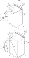
- Fig. 8 is a perspective view of the water supply unit of the refrigerator of Fig. 1 .
- the water supply unit 200 includes a housing 210 coupled detachably to the refrigerating chamber 12, and a water tank 220 coupled detachably to the housing 210, a pump 230 for pumping out the water stored in the water tank 220 to the water supply passage unit 70.
- the water supply unit 200 may further include a coupling identifying unit for allowing the user to identify the stable coupling of the water tank 220 to the housing 210.
- the water tank 220 may be formed in a box-shape that can be inserted into the housing 210. Since the water tank 220 is formed to correspond to the shape of the housing 210, the shape of the water tank 220 may vary in accordance with the shape of the housing 210.
- the coupling identifying unit is disposed through the housing 210 and the water tank 220 to allow the user to identify the coupling state of the housing 210 and the water tank 220.
- a light emitting diode which emits light when the water tank is securely coupled to the housing or a sound generating device, which generates sound, may be used as the coupling identifying unit.
- a mechanical structure that allows the user to sensually identify the coupling state of the water tank and the housing may be applied as the coupling state identifying unit. The following will describe a case where the mechanical structure is used as the coupling state identifying unit by way of example.
- the water tank 220 includes a water tank body 221 having an opened top and a cover 222 for opening/closing the opened top of the water tank body 221.
- Locking levers 225 for fixing the cover on an upper portion of the water tank 220 may be provided on both sides of the cover 222. As the locking levers 225 rotate downward, the cover 222 is fixed on the water tank 220 to maintain the sealing property and coupling force of the cover 222 to the water tank body 221.
- the cover 222 is separated from the water tank body 221, the inside of the water tank 220 can be cleaned. Therefore, the inside of the water tank 220 can be hygienically maintained. Needless to say, the cover 222 may be integrally formed with the water tank body 221.
- a water outlet 241 is formed inside the water tank 220.
- a top portion of the water outlet 241 is disposed on a top surface 16 of the cover 222.
- An insertion portion 242 is formed on an end of the water outlet 241.
- a water supply hole 223 through which the water is supplied into the water tank 220 is formed on an upper portion of the cover 222.
- a lid 224 is coupled to the water supply hole 223.
- the lid 224 and the water supply hole 223 are provided with threads so that the lid 224 can be coupled to the water supply hole 223 through a screw motion.
- a catching unit 250 is formed on an upper portion of the cover 222.
- the catching unit 250 is formed in a cam shape. That is, the catching unit 250 has a first cam surface 251 and a second cam surface 252 that are arranged in parallel with a direction in which the water tank 220 is coupled to the housing 210.
- the first and second cam surfaces 251 and 252 are symmetric with each other.
- a locking unit 213 is disposed on an upper portion of the housing 210.
- the locking unit 213 includes a disk 214 rotatably installed on the housing 210 and a catching projection 216 protruding from the disk 214.
- the locking unit 213 may further include an elastic member 217 biasing the disk 214 to an initial position. The structure of the locking unit will be described in more detail later.
- the catching unit 250 of the cover 222 and the locking unit 213 of the housing 210 form the coupling state identifying unit.
- the coupling state identifying unit 250, 213 allows the user to identify the coupling or decoupling state by a touch feel when the water tank 220 is being coupled to the housing 210.
- An installation groove 211 is formed on an upper portion of the housing 210.
- the installation groove 211 may be formed in a circular shape.
- An arc-shaped guide hole 212 is formed through the installation groove 211.
- the disk 214 is rotatably coupled to the installation groove 211.
- a pin 215 is coupled to a center of the disk 214 so that the disk 214 rotates about the pint 215.
- the catching projection 216 that is movable inserted in the guide hole 212 is formed on the disk 214.
- the elastic member 217 biases the disk 214 toward the initial position. At this point, a first end of the elastic member 217 is fixed on the disk 214 and a second end of the elastic member 217 is fixed on the installation groove 211.
- a torsion spring may be used as the elastic member 217.
- the second cam surface 252 of the catching unit 250 presses the catching projection 216 and thus the disk 214 rotates. Further, when the catching projection 216 goes over the second cam surface 252 while sliding along the second cam surface 252, the catching unit 250 is returned to the initial position by the elastic member 217. This will be described in more detail later.
- the cam-shaped catching unit 250 may be disposed on an under surface of the upper portion of the housing 210 and the water tank 220 may be disposed on the cover 222.
- the pump 230 may be coupled to the housing 210. At this point, the housing 210 may be partly opened at the top so as to receive the pump 230.
- the pump 230 communicates with the water tank 220 when the water tank 220 is coupled to the housing 210.
- a coupling portion 231 may be formed on the pump 230 so that the water outlet 241 of the water tank 220 is coupled to the coupling portion 231 when the water tank 220 is coupled to the housing 210 (see Fig. 9 ).
- the coupling portion 231 is provided with a structure that can be closely coupled to the insertion portion 242 formed on the end of the water outlet 241.
- Figs. 10 to 13 are detailed views illustrating a coupling process of the water supply unit.
- Fig. 10 to 13 show a state before the water tank 220 is coupled to the housing 210.
- the catching projection 216 is inserted into an insertion side of the water tank 220 at the guide hole 212 before the water tank 220 is coupled to the housing 210.
- the catching projection 216 moves while sliding along the second cam surface 252 of the catching unit 250. As the catching projection 216 moves and thus the disk 214 rotates about the pin 215 (rotates counterclockwise). At this point, the user can feel that the restoring force of the spring and thus identify that the water tank 220 is almost inserted into the housing 210. When the water tank 252 is further inserted, the catching projection 216 reaches a convex portion that is a center of the second and first cam surfaces 252 and 251 of the catching unit 250.
- the disk 214 since the disk 214 is biased by the elastic member 217, the disk 214 rotates in a direction (a clockwise direction) opposite to a direction in which the disk 314 rotates when the catching projection 216 is pressed. At the same time, as the disk 214 rotates in the opposite direction, the catching projection 216 moves while sliding along the first cam surface 251 of the catching unit 250.
- the biasing force of the elastic force 217 aids the pushing force inserting the water tank 220. Therefore, the user can feel that the water tank 220 is fully inserted.
- the insertion portion 242 of the water tank 220 is inserted into the coupling portion 231 of the pump 230. Therefore, the inside of the water tank 220 communicates with the pump 230 and thus the water stored in the water tank 220 is supplied to the icemaker 110 through the water supply passage unit 70 as the pump operates.
- the catching projection 216 restricts the first cam surface 251 of the catching unit 250, the water outlet pipe of the water tank 220 is not removed from the coupling portion 231 of the pump 230 even when opening/closing impact of the door 20 is transmitted to the water tank 220.
- the catching unit 250 and the locking unit 213 operates in an opposite order to the above. Therefore, a detailed description thereof will be omitted herein.
- the water outlet pipe of the water tank 220 will be removed from the coupling portion 231 of the pump 230.
- Fig. 14 is a front view of a refrigerator according to another embodiment.
- a water supply unit 200 is disposed in the storage chamber.
- An ice making unit 100 is disposed on the door 20 for the freezing compartment.
- the water supply passage unit 70 is arranged at an outer side of the main body 10. Since an installation structure of the waters supply passage unit 70 is identical to that of the foregoing embodiment, a description thereof will be omitted herein.
- the water supply passage unit 200 includes a water tank 220 and a pump 230. Since structures of the housing 210, water tank 220, and pump 230 are identical to those of the foregoing embodiment, description thereof will be omitted herein.
- the ice making unit 100 includes an icemaker 110 and an ice bank 220 for storing ice discharged from the icemaker 110. Since a structure of the icemaker 110 is same as that of the foregoing embodiment, description thereof will be omitted herein.
- the ice bank 220 is installed such that it can be taken out at the outer side of the door 20.
- an ice conveying unit, a motor, an ice crusher, and a shutter may be installed in the ice bank 330.
- a handle 331 may be formed on the front portion of the ice bank 120 so that the user can pull the ice bank 120 using the handle 331.
- the ice bank 220 has an opened top through which the ice discharge from the icemaker 110 can be received.
- a home bar door 240 may be disposed in front of the ice bank 330 so that the ice bank 330 cannot be exposed to the external side.
- a lower portion of the home bar door 340 is pivotally coupled by a hinge unit. Therefore, after opening the home bar door 340, the user can take the ice after drawing out the ice bank 330. After entering the ice bank 330, the user closes the home bar door 340.
- ice having a desired quality can be obtained.
- the freezing of the water supply passage unit supplying the water to the ice making unit can be prevented.
- the user can exactly identify if the water tank is accurately coupled or decoupled. Therefore, the industrial applicability of the present invention is very high.
Landscapes
- Engineering & Computer Science (AREA)
- Chemical & Material Sciences (AREA)
- Combustion & Propulsion (AREA)
- Physics & Mathematics (AREA)
- Mechanical Engineering (AREA)
- Thermal Sciences (AREA)
- General Engineering & Computer Science (AREA)
- Devices That Are Associated With Refrigeration Equipment (AREA)
- Cold Air Circulating Systems And Constructional Details In Refrigerators (AREA)
Claims (12)
- Réfrigérateur comprenant :un corps principal définissant un compartiment de congélation (11) et un compartiment de réfrigération (12) ;des portes (20, 30) ouvrant ou fermant respectivement le compartiment de congélation (11) et le compartiment de réfrigération (12) ;une unité de charnière (41) couplant, de manière à pouvoir tourner, la porte ouvrant ou fermant le compartiment de congélation (11) au corps principal ;une unité de fabrication de glaçons (100) qui est configurée pour fabriquer des glaçons ;une unité d'alimentation d'eau (200) qui est disposée dans le compartiment de réfrigération (12) pour stocker de l'eau, l'unité d'alimentation d'eau (200) incluant :un boîtier (210) couplé, de manière détachable, au compartiment de réfrigération (12) ;un réservoir d'eau (220) couplé, de manière détachable, au boîtier (210) ; etune pompe (230) pompant l'eau stockée dans le réservoir d'eau (220) ; etune unité de passage d'alimentation d'eau (70) raccordée à l'unité d'alimentation d'eau (200) et à l'unité de fabrication de glaçons (100) pour fournir l'eau pompée par la pompe (230) de l'unité d'alimentation d'eau (200) à l'unité de fabrication de glaçons (100), l'unité de passage d'alimentation d'eau (70) étant configurée pour être raccordée à l'unité de fabrication de glaçons (100) par l'intermédiaire de l'unité de charnière (41),caractérisé en ce que l'unité de fabrication de glaçons est disposée dans la porte (20) ouvrant ou fermant le compartiment de congélation et en ce que l'unité d'alimentation d'eau (200) comprend en outre une unité d'identification d'état de couplage incluant :une unité d'accrochage (250) disposée sur une portion supérieure du réservoir d'eau (220) ; etune unité de verrouillage (213) disposée sur une portion supérieure du boîtier (210) pour fixer l'unité d'accrochage (250) lorsque le réservoir d'eau (220) est complètement inséré dans le boîtier (210).
- Réfrigérateur selon la revendication 1, dans lequel l'unité de passage d'alimentation d'eau (70) est agencée par l'intermédiaire du compartiment de congélation (11) et raccordée à l'unité d'alimentation d'eau (200) et à l'unité de fabrication de glaçons (100) .
- Réfrigérateur selon la revendication 1, dans lequel l'unité de passage d'alimentation d'eau (70) est agencée par l'intermédiaire d'un côté extérieur du corps principal.
- Réfrigérateur selon la revendication 1, dans lequel l'unité de passage d'alimentation d'eau est encastrée dans la porte ouvrant ou fermant le compartiment de congélation (11), de sorte que l'unité de passage d'alimentation d'eau (70) ne soit pas exposée à l'air froid dans le compartiment de congélation (11).
- Réfrigérateur selon la revendication 1, dans lequel l'unité de passage d'alimentation d'eau (70) est agencée par l'intermédiaire de portions arrière et supérieure du corps principal.
- Réfrigérateur selon l'une quelconque des revendications 1 à 5, dans lequel le corps principal est pourvu, à une surface extérieure, d'une rainure (30) recevant l'unité de passage d'alimentation d'eau (70) .
- Réfrigérateur selon l'une quelconque des revendications 1 à 6, dans lequel l'unité de fabrication de glaçons comprend :une machine à glaçons (110) pour fabriquer des glaçons ; etun bac à glaçons (120) stockant les glaçons déchargés de la machine à glaçons et installé pour être retiré du côté extérieur de la porte (20).
- Réfrigérateur selon la revendication 7, comprenant en outre une porte de bar (240) installée devant l'unité de fabrication de glaçons pour ouvrir et fermer un côté extérieur du bac à glaçons.
- Réfrigérateur selon la revendication 1, dans lequel l'unité d'accrochage (250) est une unité d'accrochage de type à came,
et dans lequel l'unité de verrouillage (213) inclut :un disque (214) installé, de manière à pouvoir tourner, sur le boîtier (210) ;une saillie d'accrochage (216) faisant saillie depuis le disque (214) et tournée par l'unité d'accrochage (250) pendant que le réservoir d'eau (220) est inséré dans le boîtier (210) ; etun organe élastique (217) polarisant le disque (214) à une position initiale lorsque le réservoir d'eau (220) est complètement inséré dans le boîtier (210). - Réfrigérateur selon la revendication 9, comprenant en outre :une rainure d'installation (211) formée sur la surface supérieure du boîtier (210) et configurée pour recevoir le disque (214) ; etun trou de guidage (212) formé à travers la rainure d'installation (211) en forme d'arc et configuré pour recevoir la saillie d'accrochage (216).
- Réfrigérateur selon la revendication 10, dans lequel, lorsque le réservoir d'eau (220) est inséré dans le boîtier (210), la saillie d'accrochage (216) est pressée par une deuxième surface de came (252) de l'unité d'accrochage (250) et coulisse le long de celle-ci, et le disque (214) est polarisé par l'organe élastique (217).
- Réfrigérateur selon la revendication 11, dans lequel, lorsque le réservoir d'eau (220) est complètement inséré dans le boîtier (210), la saillie d'accrochage (216) est configurée pour revenir à la position initiale en coulissant le long d'une première surface de came (251) de l'unité d'accrochage (250).
Priority Applications (1)
| Application Number | Priority Date | Filing Date | Title |
|---|---|---|---|
| EP19175664.2A EP3561415B1 (fr) | 2007-09-12 | 2007-09-12 | Réfrigérateur |
Applications Claiming Priority (1)
| Application Number | Priority Date | Filing Date | Title |
|---|---|---|---|
| PCT/KR2007/004412 WO2009035172A1 (fr) | 2007-09-12 | 2007-09-12 | Réfrigérateur |
Related Child Applications (2)
| Application Number | Title | Priority Date | Filing Date |
|---|---|---|---|
| EP19175664.2A Division-Into EP3561415B1 (fr) | 2007-09-12 | 2007-09-12 | Réfrigérateur |
| EP19175664.2A Division EP3561415B1 (fr) | 2007-09-12 | 2007-09-12 | Réfrigérateur |
Publications (3)
| Publication Number | Publication Date |
|---|---|
| EP2198220A1 EP2198220A1 (fr) | 2010-06-23 |
| EP2198220A4 EP2198220A4 (fr) | 2015-01-07 |
| EP2198220B1 true EP2198220B1 (fr) | 2019-07-24 |
Family
ID=40452159
Family Applications (2)
| Application Number | Title | Priority Date | Filing Date |
|---|---|---|---|
| EP19175664.2A Active EP3561415B1 (fr) | 2007-09-12 | 2007-09-12 | Réfrigérateur |
| EP07808204.7A Active EP2198220B1 (fr) | 2007-09-12 | 2007-09-12 | Réfrigérateur |
Family Applications Before (1)
| Application Number | Title | Priority Date | Filing Date |
|---|---|---|---|
| EP19175664.2A Active EP3561415B1 (fr) | 2007-09-12 | 2007-09-12 | Réfrigérateur |
Country Status (7)
| Country | Link |
|---|---|
| US (1) | US8353179B2 (fr) |
| EP (2) | EP3561415B1 (fr) |
| KR (1) | KR101085295B1 (fr) |
| CN (1) | CN101512261B (fr) |
| AU (1) | AU2007358438B2 (fr) |
| MX (1) | MX2009001618A (fr) |
| WO (1) | WO2009035172A1 (fr) |
Families Citing this family (14)
| Publication number | Priority date | Publication date | Assignee | Title |
|---|---|---|---|---|
| BRPI0902419B1 (pt) * | 2009-06-29 | 2021-02-02 | Electrolux Do Brasil Sa | refrigerador |
| CN101865588A (zh) * | 2010-07-13 | 2010-10-20 | 合肥美的荣事达电冰箱有限公司 | 冰箱 |
| KR20120040891A (ko) * | 2010-10-20 | 2012-04-30 | 삼성전자주식회사 | 냉장고 |
| TR201106341A1 (tr) * | 2011-06-27 | 2013-01-21 | Ar�El�K Anon�M ��Rket� | Kapı üzerine yerleştirilen bir buz kabı içeren bir soğutucu. |
| KR101536442B1 (ko) * | 2013-11-21 | 2015-07-13 | 동부대우전자 주식회사 | 냉장고 |
| KR102186837B1 (ko) * | 2013-12-06 | 2020-12-07 | 삼성전자주식회사 | 냉장고 |
| WO2016028100A1 (fr) | 2014-08-22 | 2016-02-25 | Samsung Electronics Co., Ltd. | Réfrigérateur |
| KR102343463B1 (ko) * | 2014-08-22 | 2021-12-28 | 삼성전자주식회사 | 냉장고 |
| US11112159B2 (en) * | 2018-08-01 | 2021-09-07 | Lg Electronics Inc. | Refrigerator |
| KR102742577B1 (ko) * | 2019-03-20 | 2024-12-13 | 주식회사 대창 | 제빙기 및 이를 포함하는 냉장고 |
| US11009277B2 (en) | 2019-05-15 | 2021-05-18 | Haier Us Appliance Solutions, Inc. | Refrigator applicances having a removable ice storage bin |
| KR20220015191A (ko) * | 2020-07-30 | 2022-02-08 | 엘지전자 주식회사 | 냉장고 |
| KR20240074564A (ko) * | 2022-11-21 | 2024-05-28 | 삼성전자주식회사 | 냉장고 및 냉장고의 제어 방법 |
| CN119422028A (zh) | 2022-11-21 | 2025-02-11 | 三星电子株式会社 | 冰箱和冰箱的控制方法 |
Family Cites Families (17)
| Publication number | Priority date | Publication date | Assignee | Title |
|---|---|---|---|---|
| US3570266A (en) * | 1969-06-02 | 1971-03-16 | Gen Electric | Refrigerator including ice maker water reservoir |
| JPS5153504Y2 (fr) * | 1973-03-09 | 1976-12-21 | ||
| JPS50110868U (fr) * | 1974-02-18 | 1975-09-10 | ||
| JPS5650375Y2 (fr) * | 1976-02-18 | 1981-11-25 | ||
| US4036620A (en) * | 1976-06-04 | 1977-07-19 | General Motors Corporation | Water chilling tank for refrigerator |
| US4095439A (en) | 1976-12-10 | 1978-06-20 | Whirlpool Corporation | Movable ice receptacle |
| US5156021A (en) * | 1991-08-05 | 1992-10-20 | St Gelais Gino | Refrigerator shelf-like water tank |
| JPH061228A (ja) * | 1992-06-24 | 1994-01-11 | Fujitsu Ten Ltd | 車輪ロック防止装置 |
| JPH0611228A (ja) | 1992-06-29 | 1994-01-21 | Hitachi Ltd | 自動製氷機付き冷蔵庫 |
| JPH06249560A (ja) * | 1993-02-26 | 1994-09-06 | Sanyo Electric Co Ltd | 冷蔵庫 |
| US5787724A (en) * | 1997-06-04 | 1998-08-04 | Maytag Corporation | Dispensing assembly for top mount refrigerator |
| KR19990005701A (ko) * | 1997-06-30 | 1999-01-25 | 배순훈 | 자동제빙기의 급수장치 |
| JP3602308B2 (ja) | 1997-09-12 | 2004-12-15 | 松下冷機株式会社 | 冷蔵庫 |
| US5992908A (en) * | 1997-11-19 | 1999-11-30 | Yared; Linda Sue | Single lever draw latch |
| JP2000346509A (ja) | 1999-06-02 | 2000-12-15 | Sanyo Electric Co Ltd | 自動製氷装置 |
| FR2835870B1 (fr) * | 2002-02-14 | 2005-03-11 | Airbus France | Systeme de fermeture interpose entre deux elements |
| KR20050110209A (ko) | 2004-05-18 | 2005-11-23 | 주식회사 대창 | 제빙기 |
-
2007
- 2007-09-12 EP EP19175664.2A patent/EP3561415B1/fr active Active
- 2007-09-12 MX MX2009001618A patent/MX2009001618A/es unknown
- 2007-09-12 KR KR1020107008786A patent/KR101085295B1/ko active Active
- 2007-09-12 EP EP07808204.7A patent/EP2198220B1/fr active Active
- 2007-09-12 US US12/377,022 patent/US8353179B2/en not_active Expired - Fee Related
- 2007-09-12 AU AU2007358438A patent/AU2007358438B2/en not_active Ceased
- 2007-09-12 WO PCT/KR2007/004412 patent/WO2009035172A1/fr not_active Ceased
- 2007-09-12 CN CN2007800329322A patent/CN101512261B/zh not_active Expired - Fee Related
Non-Patent Citations (1)
| Title |
|---|
| None * |
Also Published As
| Publication number | Publication date |
|---|---|
| KR101085295B1 (ko) | 2011-11-22 |
| WO2009035172A1 (fr) | 2009-03-19 |
| CN101512261A (zh) | 2009-08-19 |
| KR20100087119A (ko) | 2010-08-03 |
| EP3561415B1 (fr) | 2022-05-25 |
| EP3561415A1 (fr) | 2019-10-30 |
| EP2198220A1 (fr) | 2010-06-23 |
| AU2007358438A1 (en) | 2009-03-19 |
| CN101512261B (zh) | 2011-04-13 |
| EP2198220A4 (fr) | 2015-01-07 |
| MX2009001618A (es) | 2009-05-08 |
| US20100192613A1 (en) | 2010-08-05 |
| AU2007358438B2 (en) | 2011-02-17 |
| US8353179B2 (en) | 2013-01-15 |
Similar Documents
| Publication | Publication Date | Title |
|---|---|---|
| EP2198220B1 (fr) | Réfrigérateur | |
| EP3864356B1 (fr) | Réfrigérateur | |
| KR101631322B1 (ko) | 냉장고 | |
| US11976865B2 (en) | Refrigerator and ice-making apparatus of refrigerator | |
| CN102388284B (zh) | 冰箱控制技术 | |
| CN102171524B (zh) | 具有分配器的冰箱 | |
| EP1916489B1 (fr) | Appareil de fabrication de glace | |
| US20130327081A1 (en) | Refrigerator | |
| EP2743622A2 (fr) | Réfrigérateur | |
| US20070289669A1 (en) | Dispenser and refrigerator having the same | |
| EP2407737A2 (fr) | Réfrigérateur | |
| KR101776297B1 (ko) | 냉장고 | |
| KR101713227B1 (ko) | 냉장고 | |
| EP2024697B1 (fr) | Réfrigérateur | |
| KR20090080250A (ko) | 냉장고의 물공급 장치 | |
| US20100175417A1 (en) | Refrigerator | |
| KR20200036455A (ko) | 냉장고 및 제빙 어셈블리 | |
| KR101652213B1 (ko) | 냉장고 | |
| CN101506601A (zh) | 冰盘组件及具有这种冰盘组件的冰箱 | |
| CN101512257B (zh) | 冰箱用制冰机 | |
| KR20190125113A (ko) | 제빙 장치 및 이를 갖는 냉장고 | |
| KR20190038275A (ko) | 냉장고 | |
| KR100776295B1 (ko) | 냉장고 | |
| US20240410639A1 (en) | Articulating door latch for a built-in icebox | |
| US20260126242A1 (en) | Refrigerator |
Legal Events
| Date | Code | Title | Description |
|---|---|---|---|
| PUAI | Public reference made under article 153(3) epc to a published international application that has entered the european phase |
Free format text: ORIGINAL CODE: 0009012 |
|
| 17P | Request for examination filed | ||
| AK | Designated contracting states | ||
| AX | Request for extension of the european patent | ||
| DAX | Request for extension of the european patent (deleted) | ||
| A4 | Supplementary search report drawn up and despatched | ||
| RIC1 | Information provided on ipc code assigned before grant | ||
| GRAP | Despatch of communication of intention to grant a patent |
Free format text: ORIGINAL CODE: EPIDOSNIGR1 |
|
| STAA | Information on the status of an ep patent application or granted ep patent |
Free format text: STATUS: GRANT OF PATENT IS INTENDED |
|
| INTG | Intention to grant announced |
Effective date: 20190205 |
|
| RAP1 | Party data changed (applicant data changed or rights of an application transferred) |
Owner name: LG ELECTRONICS INC. |
|
| GRAS | Grant fee paid |
Free format text: ORIGINAL CODE: EPIDOSNIGR3 |
|
| GRAA | (expected) grant |
Free format text: ORIGINAL CODE: 0009210 |
|
| STAA | Information on the status of an ep patent application or granted ep patent |
Free format text: STATUS: THE PATENT HAS BEEN GRANTED |
|
| AK | Designated contracting states |
Kind code of ref document: B1 Designated state(s): AT BE BG CH CY CZ DE DK EE ES FI FR GB GR HU IE IS IT LI LT LU LV MC MT NL PL PT RO SE SI SK TR |
|
| REG | Reference to a national code |
Ref country code: GB Ref legal event code: FG4D |
|
| REG | Reference to a national code |
Ref country code: CH Ref legal event code: EP |
|
| REG | Reference to a national code |
Ref country code: DE Ref legal event code: R096 Ref document number: 602007058898 Country of ref document: DE |
|
| REG | Reference to a national code |
Ref country code: AT Ref legal event code: REF Ref document number: 1158675 Country of ref document: AT Kind code of ref document: T Effective date: 20190815 |
|
| REG | Reference to a national code |
Ref country code: IE Ref legal event code: FG4D |
|
| REG | Reference to a national code |
Ref country code: NL Ref legal event code: MP Effective date: 20190724 |
|
| REG | Reference to a national code |
Ref country code: LT Ref legal event code: MG4D |
|
| REG | Reference to a national code |
Ref country code: AT Ref legal event code: MK05 Ref document number: 1158675 Country of ref document: AT Kind code of ref document: T Effective date: 20190724 |
|
| PG25 | Lapsed in a contracting state [announced via postgrant information from national office to epo] |
Ref country code: FI Free format text: LAPSE BECAUSE OF FAILURE TO SUBMIT A TRANSLATION OF THE DESCRIPTION OR TO PAY THE FEE WITHIN THE PRESCRIBED TIME-LIMIT Effective date: 20190724 Ref country code: PT Free format text: LAPSE BECAUSE OF FAILURE TO SUBMIT A TRANSLATION OF THE DESCRIPTION OR TO PAY THE FEE WITHIN THE PRESCRIBED TIME-LIMIT Effective date: 20191125 Ref country code: BG Free format text: LAPSE BECAUSE OF FAILURE TO SUBMIT A TRANSLATION OF THE DESCRIPTION OR TO PAY THE FEE WITHIN THE PRESCRIBED TIME-LIMIT Effective date: 20191024 Ref country code: NL Free format text: LAPSE BECAUSE OF FAILURE TO SUBMIT A TRANSLATION OF THE DESCRIPTION OR TO PAY THE FEE WITHIN THE PRESCRIBED TIME-LIMIT Effective date: 20190724 Ref country code: LT Free format text: LAPSE BECAUSE OF FAILURE TO SUBMIT A TRANSLATION OF THE DESCRIPTION OR TO PAY THE FEE WITHIN THE PRESCRIBED TIME-LIMIT Effective date: 20190724 Ref country code: AT Free format text: LAPSE BECAUSE OF FAILURE TO SUBMIT A TRANSLATION OF THE DESCRIPTION OR TO PAY THE FEE WITHIN THE PRESCRIBED TIME-LIMIT Effective date: 20190724 Ref country code: SE Free format text: LAPSE BECAUSE OF FAILURE TO SUBMIT A TRANSLATION OF THE DESCRIPTION OR TO PAY THE FEE WITHIN THE PRESCRIBED TIME-LIMIT Effective date: 20190724 |
|
| PG25 | Lapsed in a contracting state [announced via postgrant information from national office to epo] |
Ref country code: IS Free format text: LAPSE BECAUSE OF FAILURE TO SUBMIT A TRANSLATION OF THE DESCRIPTION OR TO PAY THE FEE WITHIN THE PRESCRIBED TIME-LIMIT Effective date: 20191124 Ref country code: GR Free format text: LAPSE BECAUSE OF FAILURE TO SUBMIT A TRANSLATION OF THE DESCRIPTION OR TO PAY THE FEE WITHIN THE PRESCRIBED TIME-LIMIT Effective date: 20191025 Ref country code: ES Free format text: LAPSE BECAUSE OF FAILURE TO SUBMIT A TRANSLATION OF THE DESCRIPTION OR TO PAY THE FEE WITHIN THE PRESCRIBED TIME-LIMIT Effective date: 20190724 Ref country code: LV Free format text: LAPSE BECAUSE OF FAILURE TO SUBMIT A TRANSLATION OF THE DESCRIPTION OR TO PAY THE FEE WITHIN THE PRESCRIBED TIME-LIMIT Effective date: 20190724 |
|
| PG25 | Lapsed in a contracting state [announced via postgrant information from national office to epo] |
Ref country code: TR Free format text: LAPSE BECAUSE OF FAILURE TO SUBMIT A TRANSLATION OF THE DESCRIPTION OR TO PAY THE FEE WITHIN THE PRESCRIBED TIME-LIMIT Effective date: 20190724 |
|
| PG25 | Lapsed in a contracting state [announced via postgrant information from national office to epo] |
Ref country code: EE Free format text: LAPSE BECAUSE OF FAILURE TO SUBMIT A TRANSLATION OF THE DESCRIPTION OR TO PAY THE FEE WITHIN THE PRESCRIBED TIME-LIMIT Effective date: 20190724 Ref country code: DK Free format text: LAPSE BECAUSE OF FAILURE TO SUBMIT A TRANSLATION OF THE DESCRIPTION OR TO PAY THE FEE WITHIN THE PRESCRIBED TIME-LIMIT Effective date: 20190724 Ref country code: RO Free format text: LAPSE BECAUSE OF FAILURE TO SUBMIT A TRANSLATION OF THE DESCRIPTION OR TO PAY THE FEE WITHIN THE PRESCRIBED TIME-LIMIT Effective date: 20190724 Ref country code: PL Free format text: LAPSE BECAUSE OF FAILURE TO SUBMIT A TRANSLATION OF THE DESCRIPTION OR TO PAY THE FEE WITHIN THE PRESCRIBED TIME-LIMIT Effective date: 20190724 |
|
| PG25 | Lapsed in a contracting state [announced via postgrant information from national office to epo] |
Ref country code: IS Free format text: LAPSE BECAUSE OF FAILURE TO SUBMIT A TRANSLATION OF THE DESCRIPTION OR TO PAY THE FEE WITHIN THE PRESCRIBED TIME-LIMIT Effective date: 20200224 Ref country code: SK Free format text: LAPSE BECAUSE OF FAILURE TO SUBMIT A TRANSLATION OF THE DESCRIPTION OR TO PAY THE FEE WITHIN THE PRESCRIBED TIME-LIMIT Effective date: 20190724 Ref country code: MC Free format text: LAPSE BECAUSE OF FAILURE TO SUBMIT A TRANSLATION OF THE DESCRIPTION OR TO PAY THE FEE WITHIN THE PRESCRIBED TIME-LIMIT Effective date: 20190724 Ref country code: CZ Free format text: LAPSE BECAUSE OF FAILURE TO SUBMIT A TRANSLATION OF THE DESCRIPTION OR TO PAY THE FEE WITHIN THE PRESCRIBED TIME-LIMIT Effective date: 20190724 |
|
| REG | Reference to a national code |
Ref country code: CH Ref legal event code: PL |
|
| REG | Reference to a national code |
Ref country code: DE Ref legal event code: R097 Ref document number: 602007058898 Country of ref document: DE |
|
| PLBE | No opposition filed within time limit |
Free format text: ORIGINAL CODE: 0009261 |
|
| STAA | Information on the status of an ep patent application or granted ep patent |
Free format text: STATUS: NO OPPOSITION FILED WITHIN TIME LIMIT |
|
| PG2D | Information on lapse in contracting state deleted |
Ref country code: IS |
|
| PG25 | Lapsed in a contracting state [announced via postgrant information from national office to epo] |
Ref country code: LI Free format text: LAPSE BECAUSE OF NON-PAYMENT OF DUE FEES Effective date: 20190930 Ref country code: LU Free format text: LAPSE BECAUSE OF NON-PAYMENT OF DUE FEES Effective date: 20190912 Ref country code: CH Free format text: LAPSE BECAUSE OF NON-PAYMENT OF DUE FEES Effective date: 20190930 Ref country code: IE Free format text: LAPSE BECAUSE OF NON-PAYMENT OF DUE FEES Effective date: 20190912 |
|
| 26N | No opposition filed |
Effective date: 20200603 |
|
| REG | Reference to a national code |
Ref country code: BE Ref legal event code: MM Effective date: 20190930 |
|
| PG25 | Lapsed in a contracting state [announced via postgrant information from national office to epo] |
Ref country code: SI Free format text: LAPSE BECAUSE OF FAILURE TO SUBMIT A TRANSLATION OF THE DESCRIPTION OR TO PAY THE FEE WITHIN THE PRESCRIBED TIME-LIMIT Effective date: 20190724 Ref country code: BE Free format text: LAPSE BECAUSE OF NON-PAYMENT OF DUE FEES Effective date: 20190930 |
|
| GBPC | Gb: european patent ceased through non-payment of renewal fee |
Effective date: 20191024 |
|
| PG25 | Lapsed in a contracting state [announced via postgrant information from national office to epo] |
Ref country code: GB Free format text: LAPSE BECAUSE OF NON-PAYMENT OF DUE FEES Effective date: 20191024 |
|
| PG25 | Lapsed in a contracting state [announced via postgrant information from national office to epo] |
Ref country code: CY Free format text: LAPSE BECAUSE OF FAILURE TO SUBMIT A TRANSLATION OF THE DESCRIPTION OR TO PAY THE FEE WITHIN THE PRESCRIBED TIME-LIMIT Effective date: 20190724 |
|
| PG25 | Lapsed in a contracting state [announced via postgrant information from national office to epo] |
Ref country code: HU Free format text: LAPSE BECAUSE OF FAILURE TO SUBMIT A TRANSLATION OF THE DESCRIPTION OR TO PAY THE FEE WITHIN THE PRESCRIBED TIME-LIMIT; INVALID AB INITIO Effective date: 20070912 Ref country code: MT Free format text: LAPSE BECAUSE OF FAILURE TO SUBMIT A TRANSLATION OF THE DESCRIPTION OR TO PAY THE FEE WITHIN THE PRESCRIBED TIME-LIMIT Effective date: 20190724 |
|
| PGFP | Annual fee paid to national office [announced via postgrant information from national office to epo] |
Ref country code: IT Payment date: 20230808 Year of fee payment: 17 |
|
| PGFP | Annual fee paid to national office [announced via postgrant information from national office to epo] |
Ref country code: FR Payment date: 20230807 Year of fee payment: 17 |
|
| PG25 | Lapsed in a contracting state [announced via postgrant information from national office to epo] |
Ref country code: IT Free format text: LAPSE BECAUSE OF NON-PAYMENT OF DUE FEES Effective date: 20240912 |
|
| PG25 | Lapsed in a contracting state [announced via postgrant information from national office to epo] |
Ref country code: FR Free format text: LAPSE BECAUSE OF NON-PAYMENT OF DUE FEES Effective date: 20240930 |
|
| PGFP | Annual fee paid to national office [announced via postgrant information from national office to epo] |
Ref country code: DE Payment date: 20250805 Year of fee payment: 19 |