EP2198490B1 - Bürstenanordnung und elektrische maschine, insbesondere elektrisches hausgerät - Google Patents
Bürstenanordnung und elektrische maschine, insbesondere elektrisches hausgerät Download PDFInfo
- Publication number
- EP2198490B1 EP2198490B1 EP08804151.2A EP08804151A EP2198490B1 EP 2198490 B1 EP2198490 B1 EP 2198490B1 EP 08804151 A EP08804151 A EP 08804151A EP 2198490 B1 EP2198490 B1 EP 2198490B1
- Authority
- EP
- European Patent Office
- Prior art keywords
- brush
- arrangement according
- sleeve
- brush arrangement
- brush sleeve
- Prior art date
- Legal status (The legal status is an assumption and is not a legal conclusion. Google has not performed a legal analysis and makes no representation as to the accuracy of the status listed.)
- Not-in-force
Links
- OKTJSMMVPCPJKN-UHFFFAOYSA-N Carbon Chemical compound [C] OKTJSMMVPCPJKN-UHFFFAOYSA-N 0.000 claims description 9
- 229910052799 carbon Inorganic materials 0.000 claims description 9
- 238000006073 displacement reaction Methods 0.000 description 8
- 230000006835 compression Effects 0.000 description 6
- 238000007906 compression Methods 0.000 description 6
- 238000004519 manufacturing process Methods 0.000 description 6
- 238000013461 design Methods 0.000 description 4
- 238000003780 insertion Methods 0.000 description 3
- 230000037431 insertion Effects 0.000 description 3
- 230000007935 neutral effect Effects 0.000 description 3
- 230000000712 assembly Effects 0.000 description 2
- 238000000429 assembly Methods 0.000 description 2
- 239000004020 conductor Substances 0.000 description 2
- 238000005553 drilling Methods 0.000 description 2
- 239000000463 material Substances 0.000 description 2
- 238000009420 retrofitting Methods 0.000 description 2
- 229910001369 Brass Inorganic materials 0.000 description 1
- 229910000831 Steel Inorganic materials 0.000 description 1
- 238000005299 abrasion Methods 0.000 description 1
- 230000015572 biosynthetic process Effects 0.000 description 1
- 230000000903 blocking effect Effects 0.000 description 1
- 239000010951 brass Substances 0.000 description 1
- 230000001419 dependent effect Effects 0.000 description 1
- 238000011161 development Methods 0.000 description 1
- 230000018109 developmental process Effects 0.000 description 1
- 239000012777 electrically insulating material Substances 0.000 description 1
- 238000005516 engineering process Methods 0.000 description 1
- -1 for example Substances 0.000 description 1
- 230000001771 impaired effect Effects 0.000 description 1
- 238000009434 installation Methods 0.000 description 1
- 238000012423 maintenance Methods 0.000 description 1
- 230000007257 malfunction Effects 0.000 description 1
- 239000012811 non-conductive material Substances 0.000 description 1
- 238000003825 pressing Methods 0.000 description 1
- 238000004080 punching Methods 0.000 description 1
- 239000010959 steel Substances 0.000 description 1
- 238000012549 training Methods 0.000 description 1
Images


Classifications
-
- H—ELECTRICITY
- H01—ELECTRIC ELEMENTS
- H01R—ELECTRICALLY-CONDUCTIVE CONNECTIONS; STRUCTURAL ASSOCIATIONS OF A PLURALITY OF MUTUALLY-INSULATED ELECTRICAL CONNECTING ELEMENTS; COUPLING DEVICES; CURRENT COLLECTORS
- H01R39/00—Rotary current collectors, distributors or interrupters
- H01R39/02—Details for dynamo electric machines
- H01R39/38—Brush holders
- H01R39/41—Brush holders cartridge type
-
- H—ELECTRICITY
- H01—ELECTRIC ELEMENTS
- H01R—ELECTRICALLY-CONDUCTIVE CONNECTIONS; STRUCTURAL ASSOCIATIONS OF A PLURALITY OF MUTUALLY-INSULATED ELECTRICAL CONNECTING ELEMENTS; COUPLING DEVICES; CURRENT COLLECTORS
- H01R39/00—Rotary current collectors, distributors or interrupters
- H01R39/02—Details for dynamo electric machines
- H01R39/38—Brush holders
- H01R39/385—Means for mechanical fixation of the brush holder
Definitions
- the invention relates to a brush assembly on an electrical machine, in particular on an electrical domestic appliance, with a brush holder receiving the brush sleeve, which can be fixed in a position of use on the housing of the machine, and an electric machine equipped therewith.
- a brush arrangement of the type mentioned is from the German patent application DE 197 17 594 A1 known.
- the relevant machine has a pot-like housing made of an electrically conductive material, in which the commutator is rotatably mounted.
- the housing holding means In the region of the end face of the housing holding means are formed, which serve to hold the carbon brushes receiving brush sleeves.
- the carbon brushes are slidably mounted in the brush sleeves and biased by a helical compression spring in the direction of the commutator. Since the brush sleeves are also electrically conductive, they must each be rigidly attached to a support member made of an electrically insulating material, in particular made of plastic, are attached. Each support member is inserted during assembly from the outside radially inwardly in the direction of the commutator in the holding means until the brush sleeves occupy their position of use.
- the contact spring of the stator comes into contact with the radial surface of the respective brush sleeve.
- locking and stop means secure the support member and thus the associated brush sleeve in all directions.
- a later replacement of support member and brush sleeve is basically by a mechanical lifting of the locking connection and a radially outward displacement possible.
- an unintentional loosening of the latching connection may occur, especially if in a fault, the temperatures in the electrical machine unusually high and the material of the support member loses strength.
- the object of the invention is to further improve the safety of such an electric machine even in the event of a fault.
- a brush arrangement of the generic type in that the brush arrangement has catch means by means of which the brush sleeve can be locked in a securing position when leaving the use position.
- the brush sleeve shifts beyond the securing position if it is released in the event of a fault. In this way, it can be ensured with the invention that the prescribed electrical safety distances are maintained even in the event of a fault, in particular with regard to the brushes and the brush sleeves.
- the catching means comprise at least one latching device which engages the brush sleeve latching in the securing position.
- a locking device can be implemented in a particularly simple and inexpensive way, the catch of the invention. This particularly ensures that Catching the brush sleeve against another directed away from the commutator displacement, especially in the direction of other electrically conductive components of the machine. This makes it possible to ensure that safety distances between the brush arrangement and other conductive components surrounding the brush arrangement are maintained even in the event of a fault.
- This embodiment of the invention may be particularly advantageous when the brush sleeve is equipped for biasing the brush with a compression spring or other suitable means which favors in the case of a release of the brush sleeve displacing this away from the commutator.
- the latching device in this case advantageously has at least one recess provided on the radial surface of the brush sleeve into which engages a latching lug in the position of use against the radial surface upon reaching the securing position and counteracts a further displacement by form-locking.
- the invention can be realized in terms of manufacturing technology particularly simple and substantially weight and cost neutral with respect to the brush sleeve.
- the recess can be formed, for example, circular or rectangular, in particular square. Such contours can be produced by drilling or, in particular, punching the recess without problems and within the framework of manufacturing steps which are required in any case, and by using tools and devices already used in the production process.
- the invention is particularly applicable to a brush assembly in which the brush sleeve is formed electrically conductive and is therefore particularly secure against unwanted contact with other electrically conductive components.
- the locking lug which is suitable for engagement in the recess when the securing position is reached is preferably formed by the contact spring of the stator, which has sufficient strength to secure the brush sleeve.
- the formation of the catch in this case requires no additional or modified components with respect to the cited prior art with the exception of the adapted brush sleeve and is therefore also essentially cost and weight neutral.
- in an exchange of the brush sleeves basically a retrofitting of existing electrical devices with catching means according to the invention, for example, in the context of an already due wear replacement, possible.
- the recesses in the radial surface of the brush sleeves are preferably arranged in the position of use in the radial direction between the commutator and the stator of the electric machine and shift in an unwanted release in the direction of the contact springs.
- the contact springs of the stator are in the position of use of the brush sleeve with advantage in the direction of the commutator inclined to the contact surface of the brush sleeve.
- the relevant contact spring engages in the recess and is deformed in a further, radially acting away from the use position on the brush sleeve force in the direction of a blocking contour.
- the invention can also be used with particular advantage in a brush arrangement in which the housing of the relevant machine is designed to be electrically conductive. Especially with such electrical devices, contact between the brush sleeve and the housing is reliably avoided.
- the brush sleeve is preferably attached at a deratigen training on an electrically insulating support member, which in turn can be used in holding means provided on the housing, in particular insertable, is.
- the support member is inserted in the course of assembly preferably in the direction of the commutator in the holding means of the housing, ie in the direction of a common mounting direction of the brush sleeve.
- the specialist staff involved in the replacement of the brush sleeve thus does not need any of the usual in terms of assembly in this case Practice divergent teaching to be taught.
- the catching means of the brush arrangement have a projecting from the brush sleeve projection which abuts in the securing position to a securing element, in particular to the contact spring.
- a projection can be produced for example with little manufacturing effort by local plastic deformation of the sleeve wall and is also substantially both weight and cost neutral.
- electric machine 1 has a pot-like housing 2, which receives on its end face 3 two similar brush assemblies 4.
- the brush assemblies 4 are arranged in mirror image with respect to a plane intersecting the axis of rotation 5 of the rotor.
- only a brush assembly 4 is shown in the drawing for simplicity and finds its correspondence on the opposite side of the housing 2, not shown.
- the structural design of the brush assembly 4 is made FIG. 2 in detail visible.
- the brush assembly 4 consists of a brush sleeve 6, in which a carbon brush 7 is arranged displaceably in the direction of the arrow A.
- the carbon brush 7 is biased by a helical compression spring 8 in the direction of the commutator 9 connected to the rotor 5, wherein the carbon brush 7 applied end of the compression spring 8 is supported on the rear wall 10 of the brush sleeve 6.
- this is displaced by the compression spring 8 in the direction of the commutator 9, whereby the abrasion is compensated until reaching a wear limit.
- the brush sleeve 6 and the housing 2 are each made of a sheet-like, electrically conductive material, for example, brass or steel sheet. These materials have a high strength, but can be easily processed by pressing, stamping or drilling to form complex parts.
- the brush sleeve 6 is undetachably connected via an angle-like projecting leg 11 and a form-fitting manner with a plate-like support member 12 which consists of an electrically non-conductive material and the brush sleeve 6 with respect to the housing 2 electrically insulated.
- the support member 12 in turn is inserted during assembly together with the brush sleeve 6 in the direction of arrow B in the housing 2 integrally formed, tab-like holding means 13 until a protruding from the support member 12 stop 14 abuts the housing 2.
- the holding means are in FIG. 1 also shown in supervision.
- the contact spring 18 of the stator 19 is elastically resilient.
- the contact spring 18 has a relative to the radial surface 17 in the direction of the commutator 9 inclined abutment region 20 which bears against the radial surface 17 under prestress.
- the contact spring 18 is a component to be provided anyway on the electric machine, which in principle can be designed basically unchanged with regard to its shape compared with suitable previously known solutions. In this case, a non-inventively equipped at first installation electrical device can be subsequently provided, for example, in the context of a maintenance operation, with the present invention corresponding catch.
- a circular recess 21 which in trouble-free operation of the electric machine 1 (as well as FIG. 5 apparent) is without function.
- the recess 21 may also have a deviating from the circular contour, which, for example, of a preferred Manufacturing process for the brush sleeve 6 or the shape of the contact spring 18 is affected.
- FIG. 7 consist of the catching means for securing the brush sleeve 6 in its securing position of a protruding from the radial surface 17 of the brush sleeve 6 away from the carbon brush 7 projection 22, which by its ramp-like mounting (arrow B) of the assembly of brush sleeve 6 and support member 12 only slightly impaired, whose displacement in the direction of arrow C, however, sets after reaching the securing position, a considerable resistance.
- basically all components known from the prior art, with the exception of the brush sleeve 6, can be used unchanged, wherein the brush sleeve 6 itself can be produced within the scope of conventional production with the features required for carrying out the invention essentially without additional costs or weight increase is.
Landscapes
- Motor Or Generator Current Collectors (AREA)
Description
- Die Erfindung betrifft eine Bürstenanordnung an einer elektrischen Maschine, insbesondere an einem elektrischen Hausgerät, mit einer die Kohlebürste aufnehmenden Bürstenhülse, welche in einer Gebrauchsstellung am Gehäuse der Maschine festlegbar ist, sowie eine damit ausgestattete elektrische Maschine.
- Eine Bürstenanordnung der eingangs genannten Art ist aus der deutschen Offenlegungsschrift
DE 197 17 594 A1 bekannt. - Die betreffende Maschine weist ein topfartiges Gehäuse aus einem elektrisch leitfähigen Material auf, in welchem der Kommutator drehbar gelagert ist. Im Bereich der Stirnfläche des Gehäuses sind Haltemittel angeformt, welche zur Halterung der die Kohlebürsten aufnehmenden Bürstenhülsen dienen. Die Kohlebürsten sind in den Bürstenhülsen verschieblich gelagert und mittels einer Schraubendruckfeder in Richtung des Kommutators vorgespannt. Da die Bürstenhülsen gleichfalls elektrisch leitend ausgebildet sind, müssen diese jeweils starr an einem Tragteil aus einem elektrisch isolierenden Werkstoff, insbesondere aus Kunststoff, befestigt werden. Jedes Tragteil wird bei der Montage von außen radial nach innen in Richtung des Kommutators in die Haltemittel eingeschoben, bis die Bürstenhülsen ihre Gebrauchsstellung einnehmen. Dabei gerät die Kontaktfeder des Stators in Anlage an die Radialfläche der betreffenden Bürstenhülse. In dieser Position sichern Rast- und Anschlagmittel das Tragteil und damit auch die zugeordnete Bürstenhülse in allen Richtungen. Ein späterer Austausch von Tragteil und Bürstenhülse ist grundsätzlich durch ein mechanisches Aufheben der Rastverbindung und ein radial nach außen gerichtetes Verschieben möglich. In seltenen Ausnahmefällen kann jedoch auch ein ungewolltes Lösen der Rastverbindung auftreten, insbesondere dann, wenn bei einer Störung die Temperaturen in der elektrischen Maschine unüblich hoch ansteigen und der Werkstoff des Tragteils an Festigkeit verliert.
- Der Erfindung liegt die Aufgabe zugrunde, die Sicherheit einer derartigen elektrischen Maschine auch bei einer Störung weiter zu verbessern.
- Diese Aufgabe wird einer gattungsgemäßen Bürstenanordnung dadurch gelöst, dass die Bürstenanordnung Fangmittel aufweist, mittels derer die Bürstenhülse beim Verlassen der Gebrauchsstellung in einer Sicherungsstellung arretierbar ist.
- Durch die Erfindung kann vorteilhaft vermieden werden, dass die Bürstenhülse sich über die Sicherungsstellung hinaus verschiebt, wenn sie sich bei einer Störung löst. Auf diese Weise kann mit der Erfindung sichergestellt werden, dass auch im Störfall die vorgeschriebenen elektrischen Sicherheitsabstände eingehalten werden, insbesondere in Bezug auf die Bürsten und die Bürstenhülsen.
- Vorteilhafte Aus- und Weiterbildungen, welche einzeln oder in Kombination miteinander eingesetzt werden können, sind Gegenstand der abhängigen Ansprüche.
- Nach einer bevorzugten Ausführung der Erfindung umfassen die Fangmittel mindestens eine Rasteinrichtung, welche die Bürstenhülse in der Sicherungsstellung rastend erfaßt. Mit einer solchen Rasteinrichtung lässt sich auf besonders einfache und preiswerte Weise das erfindungsgemäße Fangmittel realisieren. Besonders bevorzugt sichert das Fangmittel die Bürstenhülse gegen eine weitere vom Kommutator weg gerichtete Verlagerung, insbesondere in Richtung anderer elektrisch leitfähiger Komponenten der Maschine. Dadurch ist erreichbar, dass Sicherheitsabstände zwischen der Bürstenanordnung und anderen die Bürstenanordnung umgebenden leitfähigen Komponenten auch im Störfall eingehalten werden. Diese Ausführung der Erfindung kann insbesondere dann vorteilhaft sein, wenn die Bürstenhülse zum Vorspannen der Bürste mit einer Druckfeder oder einem anderen dazu geeigneten Mittel ausgestattet ist, das im Falle eines Lösens der Bürstenhülse ein Verlagern dieser vom Kommutator weg begünstigt.
- Die Rasteinrichtung weist dabei mit Vorteil mindestens eine an der Radialfläche der Bürstenhülse vorgesehene Ausnehmung auf, in welche eine in Gebrauchsstellung an der Radialfläche anliegende Rastnase beim Erreichen der Sicherungsstellung einrastet und durch Formschluß einer weiteren Verlagerung entgegen wirkt. Mit dieser Ausbildung lässt sich die Erfindung hinsichtlich der Bürstenhülse fertigungstechnisch besonders einfach und im Wesentlichen gewichts- und kostenneutral realisieren.
- Die Ausnehmung kann dabei beispielsweise kreisrund oder rechteckig, insbesondere quadratisch ausgebildet werden. Derartige Konturen können durch Bohren bzw. insbesondere Stanzen der Ausnehmung problemlos und im Rahmen von ohnehin erforderlichen Fertigungsschritten sowie unter Verwendung von bereits im Fertigungsprozess eingesetzten Werkzeugen und Vorrichtungen erzeugt werden.
- Die Erfindung ist mit besonderem Vorteil bei einer Bürstenanordnung anwendbar, bei welcher die Bürstenhülse elektrisch leitfähig ausgebildet ist und daher in besonderem Maße gegen ungewollten Kontakt mit anderen elektrisch leitenden Bauteilen zu sichern ist.
- Die beim Erreichen der Sicherungsstellung zum Eingriff in die Ausnehmung geeignete Rastnase wird bevorzugt durch die Kontaktfeder des Stators gebildet, welche eine zur Sicherung der Bürstenhülse ausreichende Festigkeit aufweist. Darüber hinaus erfordert die Ausbildung der Fangmittel in diesem Fall gegenüber dem genannten Stand der Technik mit Ausnahme der angepassten Bürstenhülse keine zusätzlichen oder modifizierten Bauteile und ist damit ebenfalls im Wesentlichen kosten- und gewichtsneutral. Außerdem ist bei einem Austausch der Bürstenhülsen grundsätzlich auch eine Nachrüstung bestehender elektrischer Geräte mit erfindungsgemäßen Fangmitteln, beispielsweise im Rahmen eines ohnehin fälligen Verschleißersatzes, möglich.
- Die Ausnehmungen in der Radialfläche der Bürstenhülsen sind in deren Gebrauchsstellung vorzugsweise in radialer Richtung zwischen Kommutator und Stator der elektrischen Maschine angeordnet und verlagern sich bei einem ungewollten Lösen in Richtung der Kontaktfedern. Durch diese Ausbildung wird der häufigsten Fehlverlagerung der Bürstenhülse im Falls einer Maschinenstörung entgegen gewirkt.
- Die Kontaktfedern des Stators liegen in Gebrauchsstellung der Bürstenhülse mit Vorteil in Richtung des Kommutator geneigt an der Anlagefläche der Bürstenhülse an. Bei Überdeckung mit der zugeordneten Ausnehmung rastet die betreffende Kontaktfeder in die Ausnehmung ein und wird bei einer weiteren, radial von der Gebrauchsstellung weg auf die Bürstenhülse wirkenden Kraft in Richtung einer sperrenden Kontur verformt. Hierdurch wird die störungsbedingte und ungewollte Verlagerung der Bürstenhülse in Richtung eines elektrischen Kontakts mit anderen elektrisch leitfähigen Bauteilen besonders zuverlässig vermieden. Ein erneutes Einschieben der Bürstenhülse zur Behebung der Störung ist jedoch weiterhin ohne nennenswert vergrößerten Kraftaufwand möglich.
- Die Erfindung ist ferner mit besonderem Vorteil bei einer Bürstenanordnung einsetzbar, bei welcher auch das Gehäuse der betreffenden Maschine elektrisch leitfähig ausgebildet ist. Gerade bei derartigen elektrischen Geräten ist ein Kontakt zwischen der Bürstenhülse und dem Gehäuse zuverlässig zu vermeiden. Die Bürstenhülse wird bei einer deratigen Ausbildung vorzugsweise an einem elektrisch isolierenden Tragteil befestigt, welches seinerseits in am Gehäuse vorgesehene Haltemittel einsetzbar, insbesondere einschiebbar, ist.
- Das Tragteil ist dabei im Zuge der Montage vorzugsweise in Richtung des Kommutators in die Haltemittel des Gehäuses einschiebbar, also in Richtung einer allgemein üblichen Montagerichtung der Bürstenhülse. Dem mit dem Austausch der Bürstenhülse befassten Fachpersonal braucht in diesem Fall also hinsichtlich der Montage keine von der üblichen Praxis abweichende Lehre vermittelt zu werden.
- Nach einer anderen bevorzugten Ausführung der Erfindung weisen die Fangmittel der Bürstenanordnung einen aus der Bürstenhülse hervorragenden Vorsprung auf, welcher in Sicherungsstellung an ein Sicherungselement, insbesondere an die Kontaktfeder, anstößt. Ein derartiger Vorsprung kann beispielsweise mit geringem Fertigungsaufwand durch örtliche plastische Verformung der Hülsenwandung erzeugt werden und ist im Wesentlichen gleichfalls sowohl gewichts- als auch kostenneutral.
- Geeignete Mittel zum Festlegen der Bürstenhülse in der Gebrauchsstellung am Gehäuse der Maschine sind aus der deutschen Offenlegungsschrift
DE 19717594 A1 bekannt, deren gesamter diesbezüglicher Inhalt durch Verweis Teil der vorliegenden Offenbarung ist. - Die Erfindung wird im Folgenden anhand schematischer Zeichnungen an zwei Ausführungsbeispielen mit weiteren Einzelheiten näher erläutert.
- Es zeigen:
- Fig. 1:
- eine Aufsicht auf das Gehäuse einer elektrischen Maschine mit einer erfindungsgemäß ausgebildeten Bürstenanordnung;
- Fig. 2:
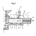
- einen Schnitt I-I durch das in
Fig. 1 dargestellte Gehäuse mit in Gebrauchsstellung befindlicher Bürstenhülse; - Fig. 3:
- den Schnitt I-I mit in Sicherungsstellung befindlicher Bürstenhülse;
- Fig. 4:
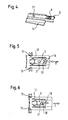
- eine perspektivische Ansicht der Baugruppe aus Bürstenhülse, Kohlebürste und Tragteil;
- Fig. 5:
- eine perspektivische Ansicht dieser Baugruppe nach dem Einsetzen in das Gehäuse in Gebrauchsstellung;
- Fig. 6:
- die zuvor genannte, perspektivisch gezeigte Baugruppe in Sicherungsstellung;
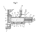
- Fig. 7:
- eine Bürstenanordnung nach einer anderen Ausführung der Erfindung.
- Die in
Figur 1 gezeigte elektrische Maschine 1 weist ein topfartiges Gehäuse 2 auf, welches an seiner Stirnfläche 3 zwei gleichartige Bürstenanordnungen 4 aufnimmt. Die Bürstenanordnungen 4 sind zueinander in Bezug auf eine die Drehachse 5 des Rotors schneidende Ebene spiegelbildlich angeordnet. In den Figuren ist zur Vereinfachung nur eine Bürstenanordnung 4 zeichnerisch dargestellt und findet auf der nicht gezeigten gegenüberliegenden Seite des Gehäuses 2 ihre Entsprechung. - Der konstruktive Aufbau der Bürstenanordnung 4 ist aus
Figur 2 im Detail ersichtlich. - Die Bürstenanordnung 4 besteht aus einer Bürstenhülse 6, in welcher eine Kohlebürste 7 in Richtung des Pfeils A verschieblich angeordnet ist. Die Kohlebürste 7 wird durch eine schraubenförmige Druckfeder 8 in Richtung des mit dem Rotor 5 verbundenen Kommutators 9 vorgespannt, wobei sich das der Kohlebürste 7 angewandte Ende der Druckfeder 8 an der Rückwand 10 der Bürstenhülse 6 abstützt. Bei einer durch Reibung am Kommutator 9 bedingten Abnutzung der Kohlebürste 7 wird diese durch die Druckfeder 8 in Richtung des Kommutators 9 verschoben, wodurch der Abrieb bis zum Erreichen einer Verschleißgrenze kompensiert wird.
- Die Bürstenhülse 6 sowie das Gehäuse 2 sind jeweils aus einem blechartigen, elektrisch leitfähigen Material gefertigt, beispielsweise aus Messing- bzw. Stahlblech. Diese Werkstoffe weisen eine hohe Festigkeit auf, lassen sich jedoch problemlos durch Pressen, Stanzen oder Bohren zu komplexen Formteilen verarbeiten.
- Die Bürstenhülse 6 ist über winkelartig auskragende Schenkel 11 unlösbar und formschlüssig mit einem plattenartigen Tragteil 12 verbunden, welches aus einem elektrisch nicht leitfähigen Werkstoff besteht und die Bürstenhülse 6 gegenüber dem Gehäuse 2 elektrisch isoliert. Das Tragteil 12 seinerseits wird bei der Montage gemeinsam mit der Bürstenhülse 6 in Richtung des Pfeils B in an das Gehäuse 2 angeformte, laschenartige Haltemittel 13 eingeschoben, bis ein aus dem Tragteil 12 hervorragender Anschlag 14 an das Gehäuse 2 anstößt. Die Haltemittel sind in
Figur 1 auch in Aufsicht dargestellt. - In der nun eingenommenen Gebrauchsstellung (Darstellung in
Figur 2 ) rasten an das Tragteil 12 angeformte Rastnasen 15 in Ausnehmungen 16 in der Stirnfläche 3 ein und sichern die Baueinheit aus Bürstenhülse 6 und Tragteil 12 bei normalem Betrieb gegen eine ungewollte Verlagerung entgegen der Richtung des Pfeils B. Hinsichtlich einer möglichen konstruktiven Ausbildung einer geeigneten Einrichtung zur Festlegung dieser Baueinheit wird noch einmal auf die DruckschriftDE 197 17 594 A1 , insbesondere auf die dortige Beschreibung des in den Zeichnungen dargestellten Ausführungsbeispiels, verwiesen. - An der dem Tragteil 12 abgewandten Radialfläche 17 liegt die Kontaktfeder 18 des Stators 19 elastisch federnd an. Die Kontaktfeder 18 weist einen gegenüber der Radialfläche 17 in Richtung des Kommutators 9 geneigten Anlagebereich 20 auf, welcher unter Vorspannung an der Radialfläche 17 anliegt. Die Kontaktfeder 18 ist ein ohnehin an der elektrischen Maschine vorzusehendes Bauteil, das hinsichtlich seiner Gestalt gegenüber geeigneten vorbekannten Lösungen grundsätzlich unverändert ausgeführt werden kann. In diesem Fall kann auch ein bei Erstmontage nicht erfindungsgemäß ausgestattetes elektrisches Gerät nachträglich, beispielsweise im Rahmen eines Wartungsvorgangs, mit der vorliegenden Erfindung entsprechenden Fangmitteln versehen werden.
- In die Bürstenhülse 6 ist ferner zwischen ihrem dem Kommutator 9 zugewandten Ende und der Kontaktfeder 18 eine im Ausführungsbeispiel kreisrunde Ausnehmung 21 vorgesehen, die bei störungsfreiem Betrieb der elektrischen Maschine 1 (wie auch aus
Figur 5 ersichtlich) ohne Funktion ist. Die Ausnehmung 21 kann auch eine von der Kreisform abweichende Kontur aufweisen, welche beispielsweise von einem bevorzugten Fertigungsverfahren für die Bürstenhülse 6 oder der Gestalt der Kontaktfeder 18 beeinflußt wird. - Bei einem in den
Figuren 3 und6 dargestellten Störfall hingegen kann unter bestimmten Umständen ungewollt eine Verlagerung der inFig. 4 gesondert abgebildeten Baueinheit aus Bürstenhülse 6 und Tragteil 12 in Richtung des Pfeils C, also entgegen der Montagerichtung, erfolgen, welche durch die Vorspannung der Druckfeder 8 begünstigt wird. Bei einer sehr weit gehenden Verschiebung der Bürstenhülse 6 besteht die Gefahr, dass diese in elektrischen Kontakt mit anderen elektrisch leitfähigen Bauteilen der elektrischen Maschine kommt. Bevor eine derartige ungewollte elektrische Verbindung auftritt, gerät jedoch der Anlagebereich 20 der Kontaktfeder 18 in Überdeckung mit der Ausnehmung 21 und fällt, da die Kontaktfeder 18 unter Spannung steht, rastend in die Ausnehmung 21 ein. In dieser Sicherungsstellung werden eine weitere Verschiebung der Baueinheit aus Bürstenhülse 6 und Tragteil 12 in Richtung des Pfeils C und damit ein elektrischer Kurzschluß verhindert. Die Störung ist jedoch grundsätzlich durch erneutes Einschieben der Baueinheit aus Bürstenhülse und Tragteil in Richtung des Pfeils B, also zum Kommutator 9 hin, wieder behebbar. - Bei dem Ausführungsbeispiel nach
Figur 7 bestehen die Fangmittel zur Sicherung der Bürstenhülse 6 in ihrer Sicherungsstellung aus einem aus der Radialfläche 17 der Bürstenhülse 6 von der Kohlebürste 7 weg ragenden Vorsprung 22, welcher durch seine rampenartige Ausbildung die Montage (Pfeil B) der Baueinheit aus Bürstenhülse 6 und Tragteil 12 nur unwesentlich beeinträchtigt, deren Verlagerung in Richtung des Pfeils C jedoch nach Erreichen der Sicherungsstellung einen erheblichen Widerstand entgegen setzt. Auch in diesem Fall können grundsätzlich alle aus dem Stand der Technik bekannten Bauteile mit Ausnahme der Bürstenhülse 6 unverändert eingesetzt werden, wobei die Bürstenhülse 6 selber im Rahmen der üblichen Fertigung mit den zur Ausführung der Erfindung erforderlichen Merkmalen im Wesentlichen ohne zusätzliche Kosten oder eine Gewichtszunahme herstellbar ist. Ebenso ist auch bei dem Ausführungsbeispiel nachFigur 7 eine Nachrüstung bestehender elektrischer Maschinen mit erfindungsgemäßen Fangmitteln möglich. - Die in der vorstehenden Beschreibung, den Ansprüchen und den Zeichnungen offenbarten Merkmale können sowohl einzeln als auch in beliebiger Kombination für die Verwirklichung der Erfindung in ihren verschiedenen Ausgestaltungen von Bedeutung sein.
Claims (13)
- Bürstenanordnung (4) an einer elektrischen Maschine (1), insbesondere an einem elektrischen Hausgerät, mit einer die Kohlebürste (7) aufnehmenden Bürstenhülse (6), welche in einer Gebrauchsstellung am Gehäuse (2) der Maschine festlegbar ist, dadurch gekennzeichnet, dass die Bürstenanordnung (4) Fangmittel aufweist, mittels derer die Bürstenhülse (6) beim Verlassen der Gebrauchsstellung in einer Sicherungsstellung arretierbar ist.
- Bürstenanordnung nach Anspruch 1, dadurch gekennzeichnet, dass die Fangmittel mindestens eine Rasteinrichtung umfassen, welche die Bürstenhülse (6) in der Sicherungsstellung rastend erfasst.
- Bürstenanordnung nach Anspruch 2, dadurch gekennzeichnet, dass die Rasteinrichtung mindestens eine an der Radialfläche (17) der Bürstenhülse (6) vorgesehene Ausnehmung (21) aufweist, in welche eine in Gebrauchsstellung an der Radialfläche anliegende Rastnase beim Erreichen der Sicherungsstellung einrastet.
- Bürstenanordnung nach Anspruch 3, dadurch gekennzeichnet, dass die Ausnehmung (21) kreisrund oder rechteckig, insbesondere quadratisch ausgebildet ist.
- Bürstenanordnung nach einem der Ansprüche 1 bis 4, dadurch gekennzeichnet, dass die Bürstenhülse (6) elektrisch leitfähig ausgebildet ist.
- Bürstenanordnung nach Anspruch 5, dadurch gekennzeichnet, dass die Rastnase durch die Kontaktfeder (18) des Stators (19) gebildet ist.
- Bürstenanordnung nach Anspruch 6, dadurch gekennzeichnet, dass die Ausnehmung (21) in Gebrauchsstellung in radialer Richtung zwischen Kommutator (9) und Stator (19) der elektrischen Maschine angeordnet ist.
- Bürstenanordnung nach Anspruch 7, dadurch gekennzeichnet, dass die Kontaktfeder (18) in Gebrauchsstellung der Bürstenhülse (6) in Richtung des Kommutators (9) geneigt an der Radialfläche (17) der Bürstenhülse anliegt.
- Bürstenanordnung nach einem der vorhergehenden Ansprüche, dadurch gekennzeichnet, dass das Gehäuse (3) der Maschine (1) elektrisch leitfähig ausgebildet ist.
- Bürstenanordnung nach Anspruch 9, dadurch gekennzeichnet, dass die Bürstenhülse (6) an einem elektrisch isolierenden Tragteil (12) befestigt ist, welches seinerseits in am Gehäuse (2) vorgesehene Haltemittel (13) einsetzbar, insbesondere einschiebbar, ist.
- Bürstenanordnung nach Anspruch 10, dadurch gekennzeichnet, dass das Tragteil (12) in Richtung des Kommutators (9) in die Haltemittel (13) des Gehäuses (2) einschiebbar ist.
- Bürstenanordnung nach Anspruch 1, dadurch gekennzeichnet, dass die Fangmittel einen Vorsprung (22) an der Bürstenhülse (6) umfassen, welcher in Sicherungsstellung an ein Sicherungselement, insbesondere an die Kontaktfeder (18), anstößt.
- Elektrische Maschine (1), insbesondere elektrisches Hausgerät, mit einer Bürstenanordnung (4) nach einem der vorhergehenden Ansprüche.
Applications Claiming Priority (2)
| Application Number | Priority Date | Filing Date | Title |
|---|---|---|---|
| DE102007047648A DE102007047648A1 (de) | 2007-10-05 | 2007-10-05 | Bürstenanordnung und elektrische Maschine, insbesondere elektrisches Hausgerät |
| PCT/EP2008/062189 WO2009047083A1 (de) | 2007-10-05 | 2008-09-12 | Bürstenanordnung und elektrische maschine, insbesondere elektrisches hausgerät |
Publications (2)
| Publication Number | Publication Date |
|---|---|
| EP2198490A1 EP2198490A1 (de) | 2010-06-23 |
| EP2198490B1 true EP2198490B1 (de) | 2013-05-01 |
Family
ID=39944427
Family Applications (1)
| Application Number | Title | Priority Date | Filing Date |
|---|---|---|---|
| EP08804151.2A Not-in-force EP2198490B1 (de) | 2007-10-05 | 2008-09-12 | Bürstenanordnung und elektrische maschine, insbesondere elektrisches hausgerät |
Country Status (8)
| Country | Link |
|---|---|
| US (1) | US20100207483A1 (de) |
| EP (1) | EP2198490B1 (de) |
| JP (1) | JP2010541174A (de) |
| KR (1) | KR20100076993A (de) |
| CN (1) | CN101816105B (de) |
| DE (1) | DE102007047648A1 (de) |
| RU (1) | RU2010114862A (de) |
| WO (1) | WO2009047083A1 (de) |
Families Citing this family (7)
| Publication number | Priority date | Publication date | Assignee | Title |
|---|---|---|---|---|
| CN102594035B (zh) * | 2011-01-07 | 2017-05-10 | 德昌电机(深圳)有限公司 | 电机 |
| CN103633525A (zh) * | 2013-11-18 | 2014-03-12 | 宝鸡航天华科机电工业有限公司 | 一种新型电刷 |
| US9601967B2 (en) * | 2014-05-02 | 2017-03-21 | The Scott Fetzer Company | Electric motor brush apparatus and method |
| CN205583897U (zh) * | 2016-03-07 | 2016-09-14 | 德昌电机(深圳)有限公司 | 电刷装置、电机及液泵 |
| CN106654784A (zh) * | 2016-12-20 | 2017-05-10 | 湖南顶立科技有限公司 | 一种平面旋转电刷 |
| WO2020255807A1 (ja) * | 2019-06-21 | 2020-12-24 | パナソニックIpマネジメント株式会社 | 電動機及び電動送風機 |
| CN116608896B (zh) | 2023-06-30 | 2023-09-19 | 常州华旋传感技术有限公司 | 电机一体式旋转变压器模拟设备及其模拟方法 |
Family Cites Families (10)
| Publication number | Priority date | Publication date | Assignee | Title |
|---|---|---|---|---|
| US3466481A (en) * | 1965-01-30 | 1969-09-09 | Ringsdorff Werke Gmbh | Brush holder with gripping lever for electrical machines |
| US3656018A (en) * | 1970-11-25 | 1972-04-11 | Gen Electric | Brush holder assembly |
| GB1438777A (en) * | 1973-09-04 | 1976-06-09 | Mullard Ltd | Electromechanical propagation devices and the manufacture thereof |
| DE3227199A1 (de) * | 1982-07-21 | 1984-01-26 | Robert Bosch Gmbh, 7000 Stuttgart | Elektromotor, insbesondere zum antreiben von hilfsaggregaten in kraftfahrzeugen |
| CN2098104U (zh) * | 1991-06-17 | 1992-03-04 | 无锡县深硕电器厂 | 供电滑触导管 |
| DE19717594B4 (de) | 1997-04-25 | 2017-09-07 | BSH Hausgeräte GmbH | Bürstenanordnung an einer elektrischen Maschine |
| JPH11234968A (ja) * | 1998-02-12 | 1999-08-27 | Asmo Co Ltd | ブラシ保持装置 |
| JP2003224946A (ja) * | 2002-01-29 | 2003-08-08 | Sanyo Electric Co Ltd | 整流子回転機 |
| GB0328386D0 (en) * | 2003-12-06 | 2004-01-14 | Johnson Electric Sa | Brush holder assembly for an electric motor |
| US7049727B2 (en) * | 2004-01-16 | 2006-05-23 | Robert Bosch Gmbh | Integrated brush-holder retention system |
-
2007
- 2007-10-05 DE DE102007047648A patent/DE102007047648A1/de not_active Withdrawn
-
2008
- 2008-09-12 JP JP2010527388A patent/JP2010541174A/ja not_active Withdrawn
- 2008-09-12 WO PCT/EP2008/062189 patent/WO2009047083A1/de not_active Ceased
- 2008-09-12 RU RU2010114862/07A patent/RU2010114862A/ru not_active Application Discontinuation
- 2008-09-12 EP EP08804151.2A patent/EP2198490B1/de not_active Not-in-force
- 2008-09-12 CN CN200880109790XA patent/CN101816105B/zh not_active Expired - Fee Related
- 2008-09-12 US US12/680,905 patent/US20100207483A1/en not_active Abandoned
- 2008-09-12 KR KR1020107009077A patent/KR20100076993A/ko not_active Withdrawn
Also Published As
| Publication number | Publication date |
|---|---|
| CN101816105B (zh) | 2013-01-23 |
| DE102007047648A1 (de) | 2009-04-09 |
| CN101816105A (zh) | 2010-08-25 |
| RU2010114862A (ru) | 2011-11-10 |
| WO2009047083A1 (de) | 2009-04-16 |
| US20100207483A1 (en) | 2010-08-19 |
| JP2010541174A (ja) | 2010-12-24 |
| KR20100076993A (ko) | 2010-07-06 |
| EP2198490A1 (de) | 2010-06-23 |
Similar Documents
| Publication | Publication Date | Title |
|---|---|---|
| EP2198490B1 (de) | Bürstenanordnung und elektrische maschine, insbesondere elektrisches hausgerät | |
| DE60114330T2 (de) | Drehverbinder mit Verriegelungsmechanismus zur Gehäuserotationsverhinderung vor dem Einbauen auf das Lenkrad | |
| DE102016116966A1 (de) | Federkraftklemmanschluss sowie Leiteranschlussklemme | |
| EP1536519A1 (de) | Leiteranschluss | |
| DE102012002145A1 (de) | Hülsenkontakt für einen elektrischen Nullkraftsteckverbinder | |
| DE102008053137B4 (de) | Steckverbindung, Stromkreis mit Steckverbindung und Betriebsverfahren | |
| DE102017117509A1 (de) | Elektrisches Gerät | |
| EP3304655A1 (de) | Verriegelungssystem für einen ladestecker | |
| WO2016079077A1 (de) | Federkraftklemme | |
| DE102012102810A1 (de) | Scheibenwischermotor und Kohlehalteplatte für einen Scheibenwischermotor | |
| DE202018107326U1 (de) | Halterahmen für einen Steckverbinder | |
| EP1921645B1 (de) | Sockeleinheit mit Ableitschiene | |
| EP2409386B1 (de) | Elektrischer antriebsmotor, insbesondere für ein aggregat in einem kraftfahrzeug | |
| DE202008008656U1 (de) | Schutzleiteranschlußvorrichtung aus Metall | |
| EP2696359A1 (de) | Elektrischer Schalter und Verfahren zum Montieren einer Schalteinheit eines elektrischen Schalters | |
| DE102016108069A1 (de) | Kontaktelement zur Ausbildung einer elektrischen Verbindung mit einem Gegenelement, elektrische Verbindung und Scheibenwischermotor | |
| DE102019104558A1 (de) | Steckverbinderteil mit einer Rasteinrichtung | |
| EP3686909A1 (de) | Elektroinstallationsgerät mit sockelaufsatz | |
| DE102016117451B4 (de) | Elektronikgehäuse | |
| DE102008058203A1 (de) | Steckbuchse für Leiterplatten | |
| DE102018133135A1 (de) | Halterahmen für einen Steckverbinder | |
| EP2750269A1 (de) | Pumpenaggregat | |
| DE102021105362A1 (de) | Frontschraubklemme | |
| DE102009009926B4 (de) | Anordnung zum Verbinden zweier Gehäuseteile | |
| DE102004058349B3 (de) | Transportsicherung für eine elektrische Maschine sowie elektrische Maschine |
Legal Events
| Date | Code | Title | Description |
|---|---|---|---|
| PUAI | Public reference made under article 153(3) epc to a published international application that has entered the european phase |
Free format text: ORIGINAL CODE: 0009012 |
|
| 17P | Request for examination filed |
Effective date: 20100506 |
|
| AK | Designated contracting states |
Kind code of ref document: A1 Designated state(s): AT BE BG CH CY CZ DE DK EE ES FI FR GB GR HR HU IE IS IT LI LT LU LV MC MT NL NO PL PT RO SE SI SK TR |
|
| AX | Request for extension of the european patent |
Extension state: AL BA MK RS |
|
| DAX | Request for extension of the european patent (deleted) | ||
| GRAP | Despatch of communication of intention to grant a patent |
Free format text: ORIGINAL CODE: EPIDOSNIGR1 |
|
| GRAS | Grant fee paid |
Free format text: ORIGINAL CODE: EPIDOSNIGR3 |
|
| GRAA | (expected) grant |
Free format text: ORIGINAL CODE: 0009210 |
|
| AK | Designated contracting states |
Kind code of ref document: B1 Designated state(s): AT BE BG CH CY CZ DE DK EE ES FI FR GB GR HR HU IE IS IT LI LT LU LV MC MT NL NO PL PT RO SE SI SK TR |
|
| REG | Reference to a national code |
Ref country code: GB Ref legal event code: FG4D Free format text: NOT ENGLISH |
|
| REG | Reference to a national code |
Ref country code: AT Ref legal event code: REF Ref document number: 610440 Country of ref document: AT Kind code of ref document: T Effective date: 20130515 Ref country code: CH Ref legal event code: EP |
|
| REG | Reference to a national code |
Ref country code: IE Ref legal event code: FG4D Free format text: LANGUAGE OF EP DOCUMENT: GERMAN |
|
| REG | Reference to a national code |
Ref country code: DE Ref legal event code: R096 Ref document number: 502008009848 Country of ref document: DE Effective date: 20130627 |
|
| REG | Reference to a national code |
Ref country code: SE Ref legal event code: TRGR |
|
| REG | Reference to a national code |
Ref country code: NL Ref legal event code: VDEP Effective date: 20130501 |
|
| REG | Reference to a national code |
Ref country code: LT Ref legal event code: MG4D |
|
| PG25 | Lapsed in a contracting state [announced via postgrant information from national office to epo] |
Ref country code: PT Free format text: LAPSE BECAUSE OF FAILURE TO SUBMIT A TRANSLATION OF THE DESCRIPTION OR TO PAY THE FEE WITHIN THE PRESCRIBED TIME-LIMIT Effective date: 20130902 Ref country code: IS Free format text: LAPSE BECAUSE OF FAILURE TO SUBMIT A TRANSLATION OF THE DESCRIPTION OR TO PAY THE FEE WITHIN THE PRESCRIBED TIME-LIMIT Effective date: 20130901 Ref country code: NO Free format text: LAPSE BECAUSE OF FAILURE TO SUBMIT A TRANSLATION OF THE DESCRIPTION OR TO PAY THE FEE WITHIN THE PRESCRIBED TIME-LIMIT Effective date: 20130801 Ref country code: ES Free format text: LAPSE BECAUSE OF FAILURE TO SUBMIT A TRANSLATION OF THE DESCRIPTION OR TO PAY THE FEE WITHIN THE PRESCRIBED TIME-LIMIT Effective date: 20130812 Ref country code: FI Free format text: LAPSE BECAUSE OF FAILURE TO SUBMIT A TRANSLATION OF THE DESCRIPTION OR TO PAY THE FEE WITHIN THE PRESCRIBED TIME-LIMIT Effective date: 20130501 Ref country code: GR Free format text: LAPSE BECAUSE OF FAILURE TO SUBMIT A TRANSLATION OF THE DESCRIPTION OR TO PAY THE FEE WITHIN THE PRESCRIBED TIME-LIMIT Effective date: 20130802 Ref country code: SI Free format text: LAPSE BECAUSE OF FAILURE TO SUBMIT A TRANSLATION OF THE DESCRIPTION OR TO PAY THE FEE WITHIN THE PRESCRIBED TIME-LIMIT Effective date: 20130501 Ref country code: LT Free format text: LAPSE BECAUSE OF FAILURE TO SUBMIT A TRANSLATION OF THE DESCRIPTION OR TO PAY THE FEE WITHIN THE PRESCRIBED TIME-LIMIT Effective date: 20130501 |
|
| PG25 | Lapsed in a contracting state [announced via postgrant information from national office to epo] |
Ref country code: BG Free format text: LAPSE BECAUSE OF FAILURE TO SUBMIT A TRANSLATION OF THE DESCRIPTION OR TO PAY THE FEE WITHIN THE PRESCRIBED TIME-LIMIT Effective date: 20130801 Ref country code: CY Free format text: LAPSE BECAUSE OF FAILURE TO SUBMIT A TRANSLATION OF THE DESCRIPTION OR TO PAY THE FEE WITHIN THE PRESCRIBED TIME-LIMIT Effective date: 20130501 Ref country code: HR Free format text: LAPSE BECAUSE OF FAILURE TO SUBMIT A TRANSLATION OF THE DESCRIPTION OR TO PAY THE FEE WITHIN THE PRESCRIBED TIME-LIMIT Effective date: 20130501 Ref country code: PL Free format text: LAPSE BECAUSE OF FAILURE TO SUBMIT A TRANSLATION OF THE DESCRIPTION OR TO PAY THE FEE WITHIN THE PRESCRIBED TIME-LIMIT Effective date: 20130501 |
|
| PG25 | Lapsed in a contracting state [announced via postgrant information from national office to epo] |
Ref country code: LV Free format text: LAPSE BECAUSE OF FAILURE TO SUBMIT A TRANSLATION OF THE DESCRIPTION OR TO PAY THE FEE WITHIN THE PRESCRIBED TIME-LIMIT Effective date: 20130501 |
|
| PG25 | Lapsed in a contracting state [announced via postgrant information from national office to epo] |
Ref country code: SK Free format text: LAPSE BECAUSE OF FAILURE TO SUBMIT A TRANSLATION OF THE DESCRIPTION OR TO PAY THE FEE WITHIN THE PRESCRIBED TIME-LIMIT Effective date: 20130501 Ref country code: CZ Free format text: LAPSE BECAUSE OF FAILURE TO SUBMIT A TRANSLATION OF THE DESCRIPTION OR TO PAY THE FEE WITHIN THE PRESCRIBED TIME-LIMIT Effective date: 20130501 Ref country code: DK Free format text: LAPSE BECAUSE OF FAILURE TO SUBMIT A TRANSLATION OF THE DESCRIPTION OR TO PAY THE FEE WITHIN THE PRESCRIBED TIME-LIMIT Effective date: 20130501 Ref country code: EE Free format text: LAPSE BECAUSE OF FAILURE TO SUBMIT A TRANSLATION OF THE DESCRIPTION OR TO PAY THE FEE WITHIN THE PRESCRIBED TIME-LIMIT Effective date: 20130501 |
|
| PG25 | Lapsed in a contracting state [announced via postgrant information from national office to epo] |
Ref country code: NL Free format text: LAPSE BECAUSE OF FAILURE TO SUBMIT A TRANSLATION OF THE DESCRIPTION OR TO PAY THE FEE WITHIN THE PRESCRIBED TIME-LIMIT Effective date: 20130501 Ref country code: RO Free format text: LAPSE BECAUSE OF FAILURE TO SUBMIT A TRANSLATION OF THE DESCRIPTION OR TO PAY THE FEE WITHIN THE PRESCRIBED TIME-LIMIT Effective date: 20130501 Ref country code: IT Free format text: LAPSE BECAUSE OF FAILURE TO SUBMIT A TRANSLATION OF THE DESCRIPTION OR TO PAY THE FEE WITHIN THE PRESCRIBED TIME-LIMIT Effective date: 20130501 |
|
| PLBE | No opposition filed within time limit |
Free format text: ORIGINAL CODE: 0009261 |
|
| STAA | Information on the status of an ep patent application or granted ep patent |
Free format text: STATUS: NO OPPOSITION FILED WITHIN TIME LIMIT |
|
| BERE | Be: lapsed |
Owner name: BSH BOSCH UND SIEMENS HAUSGERATE G.M.B.H. Effective date: 20130930 |
|
| 26N | No opposition filed |
Effective date: 20140204 |
|
| PG25 | Lapsed in a contracting state [announced via postgrant information from national office to epo] |
Ref country code: MC Free format text: LAPSE BECAUSE OF FAILURE TO SUBMIT A TRANSLATION OF THE DESCRIPTION OR TO PAY THE FEE WITHIN THE PRESCRIBED TIME-LIMIT Effective date: 20130501 |
|
| REG | Reference to a national code |
Ref country code: CH Ref legal event code: PL |
|
| REG | Reference to a national code |
Ref country code: DE Ref legal event code: R097 Ref document number: 502008009848 Country of ref document: DE Effective date: 20140204 |
|
| REG | Reference to a national code |
Ref country code: IE Ref legal event code: MM4A |
|
| PG25 | Lapsed in a contracting state [announced via postgrant information from national office to epo] |
Ref country code: IE Free format text: LAPSE BECAUSE OF NON-PAYMENT OF DUE FEES Effective date: 20130912 Ref country code: CH Free format text: LAPSE BECAUSE OF NON-PAYMENT OF DUE FEES Effective date: 20130930 Ref country code: LI Free format text: LAPSE BECAUSE OF NON-PAYMENT OF DUE FEES Effective date: 20130930 Ref country code: BE Free format text: LAPSE BECAUSE OF NON-PAYMENT OF DUE FEES Effective date: 20130930 |
|
| REG | Reference to a national code |
Ref country code: AT Ref legal event code: MM01 Ref document number: 610440 Country of ref document: AT Kind code of ref document: T Effective date: 20130912 |
|
| PG25 | Lapsed in a contracting state [announced via postgrant information from national office to epo] |
Ref country code: AT Free format text: LAPSE BECAUSE OF NON-PAYMENT OF DUE FEES Effective date: 20130912 |
|
| REG | Reference to a national code |
Ref country code: DE Ref legal event code: R081 Ref document number: 502008009848 Country of ref document: DE Owner name: BSH HAUSGERAETE GMBH, DE Free format text: FORMER OWNER: BSH BOSCH UND SIEMENS HAUSGERAETE GMBH, 81739 MUENCHEN, DE Effective date: 20150408 |
|
| PG25 | Lapsed in a contracting state [announced via postgrant information from national office to epo] |
Ref country code: MT Free format text: LAPSE BECAUSE OF FAILURE TO SUBMIT A TRANSLATION OF THE DESCRIPTION OR TO PAY THE FEE WITHIN THE PRESCRIBED TIME-LIMIT Effective date: 20130501 |
|
| PG25 | Lapsed in a contracting state [announced via postgrant information from national office to epo] |
Ref country code: LU Free format text: LAPSE BECAUSE OF NON-PAYMENT OF DUE FEES Effective date: 20130912 Ref country code: HU Free format text: LAPSE BECAUSE OF FAILURE TO SUBMIT A TRANSLATION OF THE DESCRIPTION OR TO PAY THE FEE WITHIN THE PRESCRIBED TIME-LIMIT; INVALID AB INITIO Effective date: 20080912 |
|
| REG | Reference to a national code |
Ref country code: FR Ref legal event code: PLFP Year of fee payment: 8 |
|
| REG | Reference to a national code |
Ref country code: FR Ref legal event code: CD Owner name: BSH HAUSGERATE GMBH, DE Effective date: 20151022 |
|
| REG | Reference to a national code |
Ref country code: FR Ref legal event code: PLFP Year of fee payment: 9 |
|
| REG | Reference to a national code |
Ref country code: FR Ref legal event code: PLFP Year of fee payment: 10 |
|
| REG | Reference to a national code |
Ref country code: FR Ref legal event code: PLFP Year of fee payment: 11 |
|
| PGFP | Annual fee paid to national office [announced via postgrant information from national office to epo] |
Ref country code: FR Payment date: 20180921 Year of fee payment: 11 |
|
| PGFP | Annual fee paid to national office [announced via postgrant information from national office to epo] |
Ref country code: GB Payment date: 20180924 Year of fee payment: 11 Ref country code: TR Payment date: 20180828 Year of fee payment: 11 Ref country code: SE Payment date: 20180924 Year of fee payment: 11 |
|
| PG25 | Lapsed in a contracting state [announced via postgrant information from national office to epo] |
Ref country code: SE Free format text: LAPSE BECAUSE OF NON-PAYMENT OF DUE FEES Effective date: 20190913 |
|
| REG | Reference to a national code |
Ref country code: SE Ref legal event code: EUG |
|
| GBPC | Gb: european patent ceased through non-payment of renewal fee |
Effective date: 20190912 |
|
| PG25 | Lapsed in a contracting state [announced via postgrant information from national office to epo] |
Ref country code: GB Free format text: LAPSE BECAUSE OF NON-PAYMENT OF DUE FEES Effective date: 20190912 Ref country code: FR Free format text: LAPSE BECAUSE OF NON-PAYMENT OF DUE FEES Effective date: 20190930 |
|
| PG25 | Lapsed in a contracting state [announced via postgrant information from national office to epo] |
Ref country code: TR Free format text: LAPSE BECAUSE OF NON-PAYMENT OF DUE FEES Effective date: 20190912 |
|
| PGFP | Annual fee paid to national office [announced via postgrant information from national office to epo] |
Ref country code: DE Payment date: 20220930 Year of fee payment: 15 |
|
| P01 | Opt-out of the competence of the unified patent court (upc) registered |
Effective date: 20230504 |
|
| REG | Reference to a national code |
Ref country code: DE Ref legal event code: R119 Ref document number: 502008009848 Country of ref document: DE |
|
| PG25 | Lapsed in a contracting state [announced via postgrant information from national office to epo] |
Ref country code: DE Free format text: LAPSE BECAUSE OF NON-PAYMENT OF DUE FEES Effective date: 20240403 |