EP2198697A1 - Arroseur - Google Patents
Arroseur Download PDFInfo
- Publication number
- EP2198697A1 EP2198697A1 EP09015533A EP09015533A EP2198697A1 EP 2198697 A1 EP2198697 A1 EP 2198697A1 EP 09015533 A EP09015533 A EP 09015533A EP 09015533 A EP09015533 A EP 09015533A EP 2198697 A1 EP2198697 A1 EP 2198697A1
- Authority
- EP
- European Patent Office
- Prior art keywords
- nozzle
- lid
- carrier
- sprinkler
- nozzle body
- Prior art date
- Legal status (The legal status is an assumption and is not a legal conclusion. Google has not performed a legal analysis and makes no representation as to the accuracy of the status listed.)
- Withdrawn
Links
Images
Classifications
-
- B—PERFORMING OPERATIONS; TRANSPORTING
- B05—SPRAYING OR ATOMISING IN GENERAL; APPLYING FLUENT MATERIALS TO SURFACES, IN GENERAL
- B05B—SPRAYING APPARATUS; ATOMISING APPARATUS; NOZZLES
- B05B1/00—Nozzles, spray heads or other outlets, with or without auxiliary devices such as valves, heating means
- B05B1/14—Nozzles, spray heads or other outlets, with or without auxiliary devices such as valves, heating means with multiple outlet openings; with strainers in or outside the outlet opening
- B05B1/16—Nozzles, spray heads or other outlets, with or without auxiliary devices such as valves, heating means with multiple outlet openings; with strainers in or outside the outlet opening having selectively- effective outlets
-
- B—PERFORMING OPERATIONS; TRANSPORTING
- B05—SPRAYING OR ATOMISING IN GENERAL; APPLYING FLUENT MATERIALS TO SURFACES, IN GENERAL
- B05B—SPRAYING APPARATUS; ATOMISING APPARATUS; NOZZLES
- B05B1/00—Nozzles, spray heads or other outlets, with or without auxiliary devices such as valves, heating means
- B05B1/14—Nozzles, spray heads or other outlets, with or without auxiliary devices such as valves, heating means with multiple outlet openings; with strainers in or outside the outlet opening
- B05B1/16—Nozzles, spray heads or other outlets, with or without auxiliary devices such as valves, heating means with multiple outlet openings; with strainers in or outside the outlet opening having selectively- effective outlets
- B05B1/169—Nozzles, spray heads or other outlets, with or without auxiliary devices such as valves, heating means with multiple outlet openings; with strainers in or outside the outlet opening having selectively- effective outlets having three or more selectively effective outlets
-
- B—PERFORMING OPERATIONS; TRANSPORTING
- B05—SPRAYING OR ATOMISING IN GENERAL; APPLYING FLUENT MATERIALS TO SURFACES, IN GENERAL
- B05B—SPRAYING APPARATUS; ATOMISING APPARATUS; NOZZLES
- B05B3/00—Spraying or sprinkling apparatus with moving outlet elements or moving deflecting elements
- B05B3/02—Spraying or sprinkling apparatus with moving outlet elements or moving deflecting elements with rotating elements
- B05B3/04—Spraying or sprinkling apparatus with moving outlet elements or moving deflecting elements with rotating elements driven by the liquid or other fluent material discharged, e.g. the liquid actuating a motor before passing to the outlet
- B05B3/0417—Spraying or sprinkling apparatus with moving outlet elements or moving deflecting elements with rotating elements driven by the liquid or other fluent material discharged, e.g. the liquid actuating a motor before passing to the outlet comprising a liquid driven rotor, e.g. a turbine
- B05B3/0432—Spraying or sprinkling apparatus with moving outlet elements or moving deflecting elements with rotating elements driven by the liquid or other fluent material discharged, e.g. the liquid actuating a motor before passing to the outlet comprising a liquid driven rotor, e.g. a turbine the rotation of the outlet elements being reversible
-
- B—PERFORMING OPERATIONS; TRANSPORTING
- B05—SPRAYING OR ATOMISING IN GENERAL; APPLYING FLUENT MATERIALS TO SURFACES, IN GENERAL
- B05B—SPRAYING APPARATUS; ATOMISING APPARATUS; NOZZLES
- B05B15/00—Details of spraying plant or spraying apparatus not otherwise provided for; Accessories
- B05B15/70—Arrangements for moving spray heads automatically to or from the working position
- B05B15/72—Arrangements for moving spray heads automatically to or from the working position using hydraulic or pneumatic means
- B05B15/74—Arrangements for moving spray heads automatically to or from the working position using hydraulic or pneumatic means driven by the discharged fluid
Definitions
- the invention relates to a sprinkler, in particular a pop-up sprinkler.
- nozzle body emitting the water jet within a Sets of several nozzle bodies changeable, for example, depending on the size of a variable adjustable angle sector of irrigation to choose a best adapted to the selected sector size nozzle body as the water jet emitting active nozzle body.
- a change of the nozzle body can, for. B.
- the invention has for its object to improve the possibility of correct nozzle selection in such a sprinkler, and / or to avoid inappropriate irrigation by an incorrect labeling.
- the fixed assignment of a distinguishable marking to each of the several different nozzles and their recognizability when looking at the lid of the sprinkler head allows the user to quickly understand which of the nozzles is in the position determined in the sprinkler head for discharging a jet of water, thereby also making it easy to judge it is possible whether the active nozzle body is tuned sufficiently well to the current irrigation task or a nozzle change would have to be made.
- the fixed assignment which can be arranged on a respective uniquely coupled auxiliary element both by the preferred arrangement of the marking on the respective nozzle body itself or, in particular with rotatable multi-nozzle carrier, avoids accidental false labeling, as in the case of only loose assignment of a separate handle from the nozzle bodies identification element , as the type plug mentioned above may occur.
- the marking can be given both alphanumerically and by symbols.
- the label may also have markings on the top facing lid surface, which may also be given alphanumeric or by symbols, work together.
- a window is provided in the upward-facing cover plate of the lid in a preferred embodiment.
- the window can both have a through-passage through the cover plate and be covered by a transparent pane.
- the marking is arranged behind the transparent pane within the sprinkler head.
- a carrier of the marking can close the recess in the cover plate down or in another embodiment in the receptacle over a portion of the height of the recess or this completely penetrating.
- the carrier of the marking is advantageously also used to seal the recess against the ingress of dirt into the interior of the sprinkler head.
- a locking structure is spatially associated with said window on the inside of the cover plate, which cooperates with a counterstructure of the nozzle body with the cover attached and fixes the nozzle body in its position.
- a recess in the cover plate itself can form such a locking structure.
- sprinklers with replaceable single nozzle bodies and sprinklers with replaceable nozzle which contain a multiple nozzle carrier within the sprinkler head, which is preferably rotatable about an axis of rotation relative to the sprinkler head to one of the plurality of nozzle body as active, ie the water jet dispensing nozzle body select.
- Such types of sprinklers are known in principle. With such a type of sprinkler It may be advantageously provided that the marking during rotation of the carrier of the plurality of nozzles is displaceable relative to the lid.
- the plurality of markings to be provided corresponding to the plurality of nozzles of the multiple nozzle carrier can be fixedly arranged with the nozzle carrier, for example above the respective individual nozzles, and rotated with the nozzle carrier.
- the rotation can be done both with the lid on, in which case the markings are moved by the rotation of the nozzle carrier below the window over. It can also be provided to allow a rotation of the multiple nozzle carrier only with the lid removed. In this case, it can then also be provided in the manner described for the embodiment with the individual nozzle carrier that a carrier carrying the marking engages in a recess and / or locking structure of the lid.
- a auxiliary element is provided which is coupled with the displacement, in particular the rotational movement of the nozzle carrier in the sprinkler head and in turn carries the various markings.
- an auxiliary element is coupled with a rotation of the multiple nozzle carrier and performs a linear, an arcuate or preferably a rotating movement.
- a rotationally coupled to a rotary movement of the multiple nozzle carrier auxiliary element may in particular contain a gear, which meshes via a spur gear toothing on the nozzle carrier.
- the markings on the auxiliary element may be recognizable in one of the ways described by a window in the cover plate when looking at the cover plate.
- a marking for example in the form of a directional pointer, which arranged on the top of the lid around the axis of rotation of the nozzle carrier markings for the information of the user in with a rotatable multiple nozzle carrier cooperating in such a way that the directional marking points to one of several different markings and the markers in turn contain information about the type of the nozzle body selected as being active.
- a directional marking in a rotatable multiple nozzle carrier and / or a rotatable auxiliary element does not necessarily have to be arranged on a pivot pin, but may also be present generally in the region of the axis of rotation of the multiple nozzle carrier and / or the auxiliary element and looking at the top of the lid be seen in conjunction with markings on the top of the lid.
- the arrangement of a directional marking on a pivot pin is particularly advantageous because this also at the same time a stable mounting of a rotatable member is given.
- a permutation in the sense that several permanently visible markings on the rotatable component, in particular a rotary bearing nozzle of a rotatable nozzle carrier or an auxiliary element are provided and has a single mark on the top cover on one of the several markings depending on the rotational position of the rotatable member.
- this requires a considerably larger diameter of a rotary bearing neck.
- a directional marking can also interact a position variable, with rotatable nozzle carrier in particular radially with respect to the rotational axis position variable identification of different nozzle body with in one direction in the manner of a substantially linear scale.
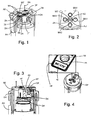
- Fig. 1 shows a first advantageous example for the display of information about an active nozzle of a nozzle assembly.
- a pop-up sprinkler which below a cover plate DP of a sprinkler head nozzle assembly with a plurality of individual nozzles, of which nozzles D3 and D4 are visible, contains in a nozzle carrier DT.
- the sprinkler head is shown in its lowered rest position, in which it rests within an outer sleeve AH, which is typically buried in the ground.
- the sprinkler head is closed by a cover plate DP upwards.
- the cover plate DP forms a one-piece cover body with a sleeve-shaped side wall DH.
- the nozzle carrier DT is rotatable about a vertical axis of rotation, which preferably coincides with the axis of rotation RA of the sprinkler head in its sprinkling operation, whereby one of the several nozzles can be brought into an operating position in which this nozzle is arranged in front of a water-supplying channel and can deliver a water jet as a selected active nozzle.
- the remaining nozzles of the multi-nozzle arrangement are inactive and can not be charged with water in their positions.
- the nozzle carrier DT is rotatable about the axis of rotation by an actuating element BE in the form of a gear with a toothing in a counter-toothing of a ring gear TR, which is rotatably connected to the part of the nozzle carrier or with this engages.
- the two teeth of the actuating element and the ring gear preferably have the same circumference, so that a rotation of the actuating element BE by a certain angle causes rotation of the ring gear TR and the nozzle carrier DT by the same angle.
- the actuating element BE protrudes with a pin ZA in an opening AU in the cover plate DP and is rotatable in this about an axis of rotation RA parallel to the axis of rotation.
- a rotation of the actuating element BE can for example take place in that in the upward-facing end face of the pin ZA a tool attachment WT is provided, in which a tool, such as a screwdriver or even a coin, can be used to the actuator BE to his Rotate the rotation axis and thus indirectly also the nozzle carrier DT to rotate about the axis of rotation RA of the sprinkler head coinciding in the example rotation axis and rotate within the group of, for example, four nozzles on the nozzle holder one of these nozzles in the operating position and thus to select as the active nozzle ,
- the operating element BE is manually accessible through a recess of the side wall DH and rotatable.
- Fig. 2 shows a plan view of the recess AU in the cover plate containing cutout.
- a directional indicia AZ for example in the form of an arrow or alternatively also in the form of an attached only at an edge portion of the circumference of the pin ZA marking, which assumes a radial direction-indicating function.
- markings MA1, MA2, MA3, MA4 are grouped around the recess and the interaction of the directional marking AZ with one of the several markings, in the example of FIG Fig. 2 marked MA1 indicates which of the multiple nozzles is in the active operating position.
- the plurality of nozzles of the multiple nozzle array on the nozzle carrier DT may be set to different angle sector ranges in their nozzle cross section, in conjunction with a variable setting of an angular sector within which the sprinkler head is alternately swung in the irrigation mode, that of the respective nozzle per unit time delivered amount of water is best matched to an angle sector range.
- an in Fig. 1 invisible, located in the active operating position nozzle D1 have a small nozzle cross section and be particularly suitable for this with an angle sector between 0 ° and 90 °, whereas the nozzle cross sections with further nozzles D2, D3, D4, of which a nozzle D2 in Fig.
- the marks MA1 to MA4 are in Fig. 2 sketched example symbolically matched to such angular ranges, wherein a mark MA2 with a 90 ° angle range symbol of the nozzle D1, the mark MA2 with a 180 ° angle range symbol of the nozzle D2, the mark MA3 with a 270 ° angle range symbol the nozzle D3 and the mark MA4 is associated with a full circle as a 360 ° angle range symbol of the nozzle D4.
- the directional marking AZ points to one of the multiple markers MA1 to MA4 and the user is informed in this way directly in a simple way, which of the several available nozzles currently active as active nozzle the operating position is located.
- a mark on the pin ZA of the operating element BE can also be provided that with the nozzle carrier DT and the ring gear TR a projecting at the axis of rotation of the nozzle carrier DT through a recess in the cover plate pin with a directional marking is provided analogous to AZ and a plurality of markings are arranged around the circumference of the recess for such a journal of the nozzle carrier DT.
- a plurality of different markings can also be arranged directly on the end face of such a pin, which can be recognized by the recess in the cover plate, and in cooperation with only one marking on the circumference of the associated recess cooperate to alert the user to the marking associated with the currently active nozzle on the end face of the pin.
- Fig. 3 shows another embodiment of a sprinkler head, again in the lowered rest position, in which within the sprinkler head only a single nozzle is provided on a single nozzle body DK, which is inserted interchangeable into a nozzle holder DA.
- a nozzle body DK On the nozzle body DK an extension HF is provided upwardly continuing, the upper end engages in a recess AK in the cover plate.
- an optical marking for the individualization of the nozzle body or its nozzle is attached.
- Such a marking KE is readable by the user through the recess AK.
- SE is in Fig. 3 denotes an actuator for setting a sector boundary of a sprinkling sector.
- Fig. 4 shows belonging to the Fig. 3 a view of the sprinkler head obliquely from above and an enlarged section to this, from which it is seen that the upwardly facing end surface of the extension of the nozzle body HF has a marking, for example in the form of an angular range indication (here 90 ° to 179 °), which through the recess AK is recognizable.
- the label can also, as already to Fig. 2 executed, have a different shape.
- the marking can also be given in this case by a direction-indicating marking, for example an arrow, if several different markings corresponding to MA1 to MA4 are again around the recess AK Fig. 2 are provided.
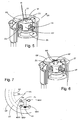
- Fig. 5 shows a sprinkler head, which is similar to the embodiment according to Fig. 1 a relative to the sprinkler head rotatable nozzle carrier DT with multiple nozzles having.
- a transparent window FE is provided in the cover plate DP and a plurality of markings KI are assigned to the individual nozzles of the multiple nozzle arrangement of the nozzle carrier DT on the upper side of the nozzle carrier DT. Assuming that the active nozzle is in an in Fig.
- the markings KI are not to be assigned to the individual nozzles located below these, but located in the area of the window FE marking A is associated with the concealed, active nozzle, the label B is another, assigned to concealed nozzle, the label C is associated with the visible nozzle D3 and the equally visible nozzle D4 associated label is hidden by the uncut portion of the cover plate DP.
- the nozzle assembly is a pin ZT in a lid recess ZU at the rotational axis of the sprinkler head, which coincide with the axis of rotation of the nozzle assembly rotatably mounted.
- a tool for. As a screwdriver or even a coin used in a tool approach in the upward-facing end face of the pin.
- Fig. 6 shows a variant too Fig. 5 in which with the same rotary mechanism to a at the axis of rotation of the sprinkler head and the nozzle assembly marks MA on the top cover, z. B. by type Fig. 2 are mounted and cooperates with a directional marking AZ on the end face of the pin ZT.
- Fig. 7 shows another example of a recognizable from the top of the sprinkler head marking one of several active nozzles on a rotatable nozzle carrier.
- the circular cover plate DP is shown symbolically and the outline of the nozzle carrier DT shown.
- a radially elongated window FL is formed and on the upper side of the nozzle carrier DT are at different distances R1, R2 from the axis of rotation of the nozzle carrier markings K1, K2, etc., of which in positioning one of the plurality of nozzles of the nozzle carrier in the Operating position one of these markers, in the example, the mark K1, in the window is visible.
- the radial positions of the markings along the window are different, so that, depending on the position within the window, markings K1, K2, etc., above the markings MA1 to MA4 applied around the window, in turn provide clear information about the respectively active nozzle.
- An appropriate disclosure of information through a linear window and along the linear extent of different markings on the top of the lid can also in conjunction with a plugged individual nozzle of in Fig. 3 sketched type be given by a position-indicating marking on the top of the extension HF is made depending on the nozzle type in different position.
Landscapes
- Details Or Accessories Of Spraying Plant Or Apparatus (AREA)
Applications Claiming Priority (1)
| Application Number | Priority Date | Filing Date | Title |
|---|---|---|---|
| DE102008063583A DE102008063583A1 (de) | 2008-12-18 | 2008-12-18 | Regner |
Publications (1)
| Publication Number | Publication Date |
|---|---|
| EP2198697A1 true EP2198697A1 (fr) | 2010-06-23 |
Family
ID=41649966
Family Applications (1)
| Application Number | Title | Priority Date | Filing Date |
|---|---|---|---|
| EP09015533A Withdrawn EP2198697A1 (fr) | 2008-12-18 | 2009-12-16 | Arroseur |
Country Status (2)
| Country | Link |
|---|---|
| EP (1) | EP2198697A1 (fr) |
| DE (1) | DE102008063583A1 (fr) |
Cited By (3)
| Publication number | Priority date | Publication date | Assignee | Title |
|---|---|---|---|---|
| WO2010115600A1 (fr) * | 2009-04-11 | 2010-10-14 | Gardena Manufacturing Gmbh | Dispositif d'arrosage enterré |
| CN104838978A (zh) * | 2015-05-29 | 2015-08-19 | 安徽浮山现代家庭农场有限公司 | 一种灌溉器 |
| CN107051942A (zh) * | 2017-03-24 | 2017-08-18 | 南阳理工学院 | 环卫作业车辆的自动喷洒系统 |
Citations (4)
| Publication number | Priority date | Publication date | Assignee | Title |
|---|---|---|---|---|
| EP0410198A2 (fr) * | 1989-07-27 | 1991-01-30 | GARDENA Kress + Kastner GmbH | Arroseur escamotable |
| US5765757A (en) * | 1995-12-14 | 1998-06-16 | Hunter Industries Incorporated | Quick select nozzle system |
| US6182909B1 (en) * | 1998-08-03 | 2001-02-06 | Carl L. C. Kah, Jr. | Rotary nozzle assembly having insertable rotatable nozzle disc |
| US20030089796A1 (en) * | 1998-12-11 | 2003-05-15 | Kah Carl L. C. | Rotary driven sprinkler with multiple nozzle ring |
-
2008
- 2008-12-18 DE DE102008063583A patent/DE102008063583A1/de not_active Withdrawn
-
2009
- 2009-12-16 EP EP09015533A patent/EP2198697A1/fr not_active Withdrawn
Patent Citations (4)
| Publication number | Priority date | Publication date | Assignee | Title |
|---|---|---|---|---|
| EP0410198A2 (fr) * | 1989-07-27 | 1991-01-30 | GARDENA Kress + Kastner GmbH | Arroseur escamotable |
| US5765757A (en) * | 1995-12-14 | 1998-06-16 | Hunter Industries Incorporated | Quick select nozzle system |
| US6182909B1 (en) * | 1998-08-03 | 2001-02-06 | Carl L. C. Kah, Jr. | Rotary nozzle assembly having insertable rotatable nozzle disc |
| US20030089796A1 (en) * | 1998-12-11 | 2003-05-15 | Kah Carl L. C. | Rotary driven sprinkler with multiple nozzle ring |
Cited By (4)
| Publication number | Priority date | Publication date | Assignee | Title |
|---|---|---|---|---|
| WO2010115600A1 (fr) * | 2009-04-11 | 2010-10-14 | Gardena Manufacturing Gmbh | Dispositif d'arrosage enterré |
| CN104838978A (zh) * | 2015-05-29 | 2015-08-19 | 安徽浮山现代家庭农场有限公司 | 一种灌溉器 |
| CN107051942A (zh) * | 2017-03-24 | 2017-08-18 | 南阳理工学院 | 环卫作业车辆的自动喷洒系统 |
| CN107051942B (zh) * | 2017-03-24 | 2023-03-10 | 南阳理工学院 | 环卫作业车辆的自动喷洒系统 |
Also Published As
| Publication number | Publication date |
|---|---|
| DE102008063583A1 (de) | 2010-06-24 |
Similar Documents
| Publication | Publication Date | Title |
|---|---|---|
| DE19817953A1 (de) | Markiervorrichtung | |
| EP0077484A2 (fr) | Brosse à dents | |
| DE10207872B4 (de) | Vorrichtung zur Auswahl aus einer Menüstruktur und zur Steuerung einer zugeordneten Bildschirmanzeige | |
| DE102008063583A1 (de) | Regner | |
| DE20301749U1 (de) | Stelleinrichtung und damit ausgestattetes Zielfernrohr | |
| EP1215478A2 (fr) | Dispositif d'indication de pression | |
| DE3741535C2 (fr) | ||
| DE60201352T2 (de) | Ablaufanzeigevorrichtung für uhren | |
| DE3148853C2 (de) | Schlagwerksuhr mit Vorrichtung zum zeitweisen Verhindern des Gong- oder Glockenschlages | |
| DE712799C (de) | Spitzmaschine fuer Schreib-, Zeichen- und Malstifte | |
| EP2401903B1 (fr) | Dispositif de commutation pour une machine de répartition agricole destinée à sortir des semences et/ou de l'engrais | |
| CH688014B5 (de) | Zeitanzeigevorrichtung. | |
| DE102008063586A1 (de) | Regner | |
| DE102007011594B4 (de) | Zentrale Datumsvorrichtung | |
| DE202011050887U1 (de) | Drehmomentwerkzeug | |
| DE3334005C2 (fr) | ||
| DE102007038202B3 (de) | 24-Stunden-Anzeige für eine Uhr mit Zeigern | |
| EP0154211B1 (fr) | Dispositif d'impression | |
| DE1119587B (de) | Regner mit Schwinghebel | |
| DE702761C (de) | Uhr zur Angabe der Zeit in Bogengraden | |
| DE2642541C3 (de) | Schreibgerät mit Anzeigevorrichtung | |
| DE2357313A1 (de) | Vorrichtung fuer stunden- und minutenanzeige | |
| EP0065308B1 (fr) | Dispositif mécanique de comptage à prérégulation pour une machine à copier | |
| DE690841C (de) | Anzeigeelement fuer Grossflaechenskalen von Rundfunkempfaengern | |
| DE545739C (de) | Selbstverkaeufer, insbesondere zur Ausgabe von Versicherungspolicen |
Legal Events
| Date | Code | Title | Description |
|---|---|---|---|
| PUAI | Public reference made under article 153(3) epc to a published international application that has entered the european phase |
Free format text: ORIGINAL CODE: 0009012 |
|
| AK | Designated contracting states |
Kind code of ref document: A1 Designated state(s): AT BE BG CH CY CZ DE DK EE ES FI FR GB GR HR HU IE IS IT LI LT LU LV MC MK MT NL NO PL PT RO SE SI SK SM TR |
|
| AX | Request for extension of the european patent |
Extension state: AL BA RS |
|
| STAA | Information on the status of an ep patent application or granted ep patent |
Free format text: STATUS: THE APPLICATION IS DEEMED TO BE WITHDRAWN |
|
| 18D | Application deemed to be withdrawn |
Effective date: 20101224 |