EP2198763A2 - Siège de toilettes - Google Patents
Siège de toilettes Download PDFInfo
- Publication number
- EP2198763A2 EP2198763A2 EP20090401035 EP09401035A EP2198763A2 EP 2198763 A2 EP2198763 A2 EP 2198763A2 EP 20090401035 EP20090401035 EP 20090401035 EP 09401035 A EP09401035 A EP 09401035A EP 2198763 A2 EP2198763 A2 EP 2198763A2
- Authority
- EP
- European Patent Office
- Prior art keywords
- toilet seat
- toilet
- spray
- seat according
- sleeve
- Prior art date
- Legal status (The legal status is an assumption and is not a legal conclusion. Google has not performed a legal analysis and makes no representation as to the accuracy of the status listed.)
- Withdrawn
Links
Images


Classifications
-
- A—HUMAN NECESSITIES
- A47—FURNITURE; DOMESTIC ARTICLES OR APPLIANCES; COFFEE MILLS; SPICE MILLS; SUCTION CLEANERS IN GENERAL
- A47K—SANITARY EQUIPMENT; ACCESSORIES THEREFOR, e.g. TOILET ACCESSORIES
- A47K13/00—Seats or covers for all kinds of closets
- A47K13/24—Parts or details not covered in, or of interest apart from, groups A47K13/02 - A47K13/22
-
- A—HUMAN NECESSITIES
- A47—FURNITURE; DOMESTIC ARTICLES OR APPLIANCES; COFFEE MILLS; SPICE MILLS; SUCTION CLEANERS IN GENERAL
- A47K—SANITARY EQUIPMENT; ACCESSORIES THEREFOR, e.g. TOILET ACCESSORIES
- A47K13/00—Seats or covers for all kinds of closets
- A47K13/12—Hinges
-
- A—HUMAN NECESSITIES
- A47—FURNITURE; DOMESTIC ARTICLES OR APPLIANCES; COFFEE MILLS; SPICE MILLS; SUCTION CLEANERS IN GENERAL
- A47K—SANITARY EQUIPMENT; ACCESSORIES THEREFOR, e.g. TOILET ACCESSORIES
- A47K13/00—Seats or covers for all kinds of closets
- A47K13/24—Parts or details not covered in, or of interest apart from, groups A47K13/02 - A47K13/22
- A47K13/30—Seats having provisions for heating, deodorising or the like, e.g. ventilating, noise-damping or cleaning devices
-
- E—FIXED CONSTRUCTIONS
- E03—WATER SUPPLY; SEWERAGE
- E03D—WATER-CLOSETS OR URINALS WITH FLUSHING DEVICES; FLUSHING VALVES THEREFOR
- E03D9/00—Sanitary or other accessories for lavatories ; Devices for cleaning or disinfecting the toilet room or the toilet bowl; Devices for eliminating smells
- E03D9/007—Devices for eliminating smells by diffusing deodorants in lavatories
Definitions
- the present invention relates to a toilet seat comprising means for dispensing a fragrance when using the toilet.
- suction devices are generally used, as for example in the DE 297 14 137 U1 are described.
- the triggering of the flush causes via a coupling a hydraulically braked lowering of the lid on the toilet seat.
- a disinfecting and / or deodorizing device can be actuated.
- a deodorizing device here a commercial room spray with push button valve is provided.
- a disadvantage of such sprays, which are designed for one-handed use, is that they are to shake before use in order to ensure a homogeneous mixing of propellant gas and perfume aerosol. It is thus firmly integrated into a dispensing device that causes segregation and inadequate, irregular release of aerosol.
- a spray device for sanitary systems with articulated seat element is known in which the spraying device, comprising an aerosol pressure vessel with control device, is connected via the control device with the hinge mechanism. By pivoting the seat member, a dispensing valve is opened via the control device and sprayed liquid out of the container.
- a valve for removing the deodorant from the pressure vessel which, as already described above, can not ensure a homogeneous, repeatable release of deodorant.
- a deodorant device for toilet seats of cisterns toilets in which a deodorant distributor between toilet seat and cistern is arranged and has a laterally oriented release device.
- the triggering device the delivery of deodorant is effected from a pressure valve via a discharge channel into the toilet inside.
- the dispenser can be connected in the form of a push button with a lever mechanism.
- a disadvantage of this device is the cistern and seat additionally arranged lying deodorant distributor. On the underside of the deodorant distributor, the surface of the sanitary ware is inaccessible, as a result of which rapidly polluting, unsightly areas are formed.
- the blind hole has lateral opening slots, in which engages at least one hinge pin, wherein the blind hole can be closed when inserted hinge pin with a cap.
- the blind hole holder of the hinge pin is in turn connected via behind-reaching screw with the toilet itself.
- the blind hole can also be used to hold a deodorant container.
- the disadvantage of this is that you have to be at least partially unscrewed and separated from complex facilities mounted in each other in order to expose access to the closed by hinge pin blind hole.
- One The built-in deodorant container is hardly accessible and interchangeable only with much effort.
- the object of the present invention is to provide a toilet seat comprising a device for dispensing a fragrance when using the toilet of the aforementioned type, which does not require built-in suction devices such as fans or the like and without external suction and complex installations ,
- a spray device integrated into the toilet seat which emits a fragrance when actuated, wherein a mechanism for triggering the spray device in the hinge area between toilet seat and toilet lid is arranged, which acts upon closing or opening the toilet lid on the spray device and triggers this.
- the invention thus takes a fundamentally different route than the prior art. Extraction or recirculation is not considered necessary. There is only a release of a fragrance when using the toilet.
- manually operated spraying devices for dispensing fragrances in the form of room spray in spray cans are known. However, these must be operated by a person, so that there is no guarantee that such an operation also takes place.
- the present invention shows superior, since in any case the operation of the spray device is forcibly ensured when closing or opening the lid of the toilet seat.
- the commonly associated via a hinge (joint) unit of toilet seat and toilet lid is referred to as a toilet seat.
- the toilet seat When using the toilet, the toilet seat remains in its horizontal position while the toilet lid is opened and folded up. In this pivoting movement, the lid rotates generally about a horizontal connecting axis in the hinge area.
- the spraying of the fragrance is triggered. This release can also be provided additionally or optionally alternatively when opening the lid. Due to the relative movement of both components toilet lid and toilet seat each other can be acted upon, for example via a built-in mechanism thrust element a trigger of the spray device.
- the toilet seat has a mounted in the hinge area removable holder that receives the spray device.
- This holder may for example be releasably attached to a bearing part, which is fixedly mounted on the toilet bowl.
- This bearing part can preferably also serve for the pivotable attachment of toilet lid and toilet seat.
- the holder can be easily removed, for example via a positive connection with the bearing part, so that you do not need a tool, for example, if you want to replace an empty spray can or if there is a defect on the sprayer. To do this, for example, with a handle, the holder from the toilet seat and opens a lid or a flap of the holder, whereupon then the spray device can be removed.
- a preferred variant of the task solution according to the invention further provides that the thrust element cooperates with a pivot, which is rotatably connected to the toilet lid.
- the rotational movement of such a pivot when pivoting the toilet lid can be implemented via suitable means in an axial movement of the pusher. This pusher is then advanced a bit, for example when closing the toilet lid and thereby acts on a spray head of the sprayer so that it is triggered.
- the thrust element is guided axially displaceably and non-rotatably in a sleeve, so as to prevent the thrust element being rotated during a rotational movement of the pivot.
- a sleeve can, for example, in a Gelenkanformung the bearing part be kept unrotatable.
- Particularly preferred is the use of at least two such sleeves each in the region of the articulations of the bearing part.
- toilet seat according to the invention with a spray device for a fragrance visually differs only slightly from a toilet seat conventional design, which promotes its acceptance by the consumer. Changes exist in particular in the joint areas. The construction height is at most slightly larger than in a conventional toilet seat. This is different from the mentioned known solutions with suction device in the toilet seat, which are much bulkier than a conventional toilet seat.
- FIG. 1 shows a perspective view of a portion of a toilet seat according to the invention, namely the joint area, which is of interest in the present case, looking in the drawing from the bottom of the toilet seat, so that the toilet seat 12 in the representation before the Toilet lid 11 is located.
- the toilet seat comprises first as a conventional toilet seat, a bearing part 10 which is attached to a toilet bowl and thus represents the fixed part of the joint to which the toilet lid 11 and the toilet seat 12 are each articulated.
- On the bearing part 10 there is a first Gelenkanformung 13 and at a distance to a second Gelenkanformung 14.
- hinge eyes 17, 18 At the toilet seat 12 are two hinge eyes 17, 18 so that the toilet seat 12 independently of the toilet lid on the toilet bowl on the bearing part 10 pivotally attached is, these hinge eyes 17, 18 in the mounted state in each case outwardly adjoin the two Gelenkanformungen 13, 14 and adjacent to these.
- hinge eyes 17, 18 At the toilet lid 11 are also two spaced hinge eyes 15, 16 are mounted for the pivotal attachment to the toilet bowl. The arrangement is in the assembled state so that the two joint eyes 15, 16 of the toilet lid 11 are furthest outward, then each inwardly in the axial direction, the two joint eyes 17 and 18 of the toilet seat 12 follow and then as each furthest inside Hinge elements join the two Gelenkanformmaschine 13, 14 of the bearing part 10, as well as the two Figures 2 and 5 can take.
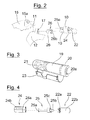
- the pivot bearing comprises the socket 26, pivot 25, first sleeve 24 and pusher 22.
- the pivot bearing comprises the plug-in pin 29, the plug-in axis 28 and the second sleeve 27. The details of this arrangement are apparent from the FIGS. 5 and 6 and will be explained in more detail below.
- the sprayer (spray can) 19 is like FIG. 3 shows recorded in a holder 20, from which it can be removed.
- the holder 20 is in turn removably mounted on the bearing part 10, so that it can be removed, for example, for the purpose of replacing the empty spray device of the toilet seat.
- the components used for the mounting of the holder 20 will be explained in more detail below.
- the spraying device comprises a spray head 21, which is axially movable in the direction of the spray can and which has an in FIG. 2 recognizable thrust element 22 can be acted upon, so that it is pressed and then triggers a spray.
- the thrust element 22 is guided during its axial movement and is held in the region of the first Gelenkanformung 13 of the bearing part 10 axially displaceable.
- the movement of the pusher element is triggered by a mechanism which is coupled to a pivotal movement of the toilet lid 11, so that, for example, when closing the toilet lid 11, an axial feed movement of the pusher 22 over a certain distance is triggered, which causes the pusher element 22 on pushes the spray head 21.
- the pusher moves back to the starting position.
- the holder 20 for the spray can 19 has a pivotally mounted cover 23, which can be opened so that you can then remove the spray can 19 from the holder 20.
- the thrust element 22 is received in the mounted state of a first sleeve 24, which in turn can be inserted up to a stop 24 a in a corresponding receptacle of Gelenkanformung 13 of the bearing part 10.
- the first sleeve has 24 guide surfaces 24 b, which are formed by flats (see FIG.
- the socket 26 is pushed with its shaft through the hole 17 a of the joint eye 17 of the toilet seat 12 through, as shown in FIG. 2 is indicated.
- the plug-in sleeve 26 is rotatably connected via a positive connection with the hinge eye 15 of the toilet lid 11, wherein, however, the rotatability of the socket 26 is given in the joint eye 17 of the toilet seat 12.
- the plug-in sleeve 26 is rotatably connected via its plug-in receptacle 26 b with the plug-in extension 25 a of the pivot pin 25, so that a rotational movement of the toilet lid 11 is transmitted via the hinge eye 15 and the socket 26 and on the pivot pin 25.
- This pivot pin 25 is freely rotatable within the first sleeve 24.
- At its end facing away from the plug-in extension 25 a of the pivot pin 25 has a cylindrical guide pin 25 b, which in a suitable in FIG. 4 unrecognizable bore of the thrust element 22 engages.
- 25 bevels 25 c or curved surfaces are formed at this end of the plug-in extension, so that there is an inclined plane, which cooperate with corresponding slopes 22 a on the thrust element 22.
- pivot 25 and thrust element 22 engage at least partially in one another.
- the corresponding ramps or elements of an inclined plane of pivot 25 and pusher 22 slide on each other, displacing the pusher in the axial direction, reducing the engagement of the elements, and increasing the axial spacing of the pivot and pusher ends.
- the thrust element 22 can not twist, since the outer contour 22 b of the thrust element 22 is selected outside with surfaces so that it engages positively in the corresponding inner contour of the first sleeve 24. Their inner contour results from inner surfaces, which in FIG. 4 correspond to visible outer guide surfaces.
- FIGS. 5 and 6 the storage of Toilettenbrille12 and the toilet lid 11 at the second Gelenkanformung 14 of the bearing part 10 explained.
- the second Gelenkanformung of firmly mounted on the toilet bowl Bearing part 10 receives a sleeve 27.
- This second sleeve 27 may be designed as well as the first sleeve 24, but is aligned in the mounted position to this mirror image.
- This second sleeve 27 takes as FIG. 6 shows the cylindrical portion 28 a of a thru-axle 28 rotatably.
- the other end of the thru axle 28 is not cylindrical but has lateral surfaces by flats 28 b, so that there is an outer profile, which corresponds to the inner profile of a socket 29 b a socket 29 so that the thru axle 28 are rotationally connected to the socket 29 can.
- This plug-in sleeve 29 corresponds in principle to the plug-in sleeve 26 already described above. However, on this side of the bearing, the bores in the joint parts are designed differently than on the other in FIG. 2 presented page.
- the joint eye 18 of the toilet seat 12 is not a round hole but a contour hole 18 a
- the joint eye 16 of the toilet lid 11 is a round receptacle 16 a (round hole)
- the receptacle 29 is positively received in the receptacle 18 a in the joint eye 18, since this receptacle 18 a has an inner contour corresponding to the outer contour with the flats 29 a of the receptacle 29.
- the plug-in sleeve 29 is rotatably held in the receptacle 18 a and thus the toilet seat 12 is rotatably mounted in the second sleeve 27 via the plug-in sleeve 29 and the plug-in axis 28 connected thereto.
- the second sleeve 27 is as well as the first sleeve 24 with a stop 27 a and 27 b provided guide surfaces and is positively received in a receptacle of the second Gelenkanformung 14 of the bearing part 10 and thus held against rotation in this Gelenkanformung 14.
- the toilet seat 12 thus has a pivot bearing on the Gelenkanformung 14 of the bearing part 10, but is characterized in that the plug sleeve 29 ends rotate freely in the receptacle 16 a, pivotally mounted on this side regardless of the pivoting movement of the toilet lid 11.
- the fixedly connected to the toilet bowl bearing part 10 thus serves as a pivot bearing for toilet lid 11 and toilet seat 12.
- the two sleeves 24 and 27 are each received up to their stop 24 a and 27 a in the Gelenkanformungen 13 and 14, but each one Head area survives as you look FIG. 2 respectively.
- FIG. 5 can recognize. Due to the mirror-image arrangement of the two sleeves 24, 27, these head portions project respectively inwards and face each other.
- these head portions of the two sleeves 24, 27 have outer contour surfaces, one can push the two ends of the holder 20 for the spray device form-fitting on these head portions of the sleeves, wherein formed on the holder 20 corresponding to the contour surfaces of the sleeves Engagement surfaces 20 a are located (see FIG. 3 ).
- the bearing part continues to serve also for releasably attaching the holder 20 for the spray device.
Landscapes
- Health & Medical Sciences (AREA)
- Public Health (AREA)
- Epidemiology (AREA)
- Life Sciences & Earth Sciences (AREA)
- Engineering & Computer Science (AREA)
- Hydrology & Water Resources (AREA)
- Water Supply & Treatment (AREA)
- Toilet Supplies (AREA)
Applications Claiming Priority (1)
| Application Number | Priority Date | Filing Date | Title |
|---|---|---|---|
| DE200820013833 DE202008013833U1 (de) | 2008-12-19 | 2008-12-19 | Toilettensitz |
Publications (1)
| Publication Number | Publication Date |
|---|---|
| EP2198763A2 true EP2198763A2 (fr) | 2010-06-23 |
Family
ID=40418560
Family Applications (1)
| Application Number | Title | Priority Date | Filing Date |
|---|---|---|---|
| EP20090401035 Withdrawn EP2198763A2 (fr) | 2008-12-19 | 2009-11-09 | Siège de toilettes |
Country Status (2)
| Country | Link |
|---|---|
| EP (1) | EP2198763A2 (fr) |
| DE (1) | DE202008013833U1 (fr) |
Cited By (2)
| Publication number | Priority date | Publication date | Assignee | Title |
|---|---|---|---|---|
| EP2753576B1 (fr) | 2011-09-09 | 2016-02-03 | ThyssenKrupp Industrial Solutions AG | Dispositif pour réduire le phénomène de by-pass dans des brûleurs d'oxydation d'ammoniac |
| JP2023048754A (ja) * | 2021-09-28 | 2023-04-07 | Toto株式会社 | トイレ装置 |
Families Citing this family (1)
| Publication number | Priority date | Publication date | Assignee | Title |
|---|---|---|---|---|
| CN115928850B (zh) * | 2022-12-14 | 2026-02-06 | 浙江怡和卫浴有限公司 | 一种喷水机构和智能坐便器 |
Family Cites Families (3)
| Publication number | Priority date | Publication date | Assignee | Title |
|---|---|---|---|---|
| US5345617A (en) | 1993-11-12 | 1994-09-13 | Jahner James F | Toilet seat air freshener |
| US5781937A (en) | 1997-06-20 | 1998-07-21 | Liang; Ming-Feng | Toilet deodorizing system |
| US20080256692A1 (en) | 2007-04-17 | 2008-10-23 | Bruce Edward Barton | Novel Toilet Air Treatment Device |
-
2008
- 2008-12-19 DE DE200820013833 patent/DE202008013833U1/de not_active Expired - Lifetime
-
2009
- 2009-11-09 EP EP20090401035 patent/EP2198763A2/fr not_active Withdrawn
Cited By (3)
| Publication number | Priority date | Publication date | Assignee | Title |
|---|---|---|---|---|
| EP2753576B1 (fr) | 2011-09-09 | 2016-02-03 | ThyssenKrupp Industrial Solutions AG | Dispositif pour réduire le phénomène de by-pass dans des brûleurs d'oxydation d'ammoniac |
| JP2023048754A (ja) * | 2021-09-28 | 2023-04-07 | Toto株式会社 | トイレ装置 |
| JP7454535B2 (ja) | 2021-09-28 | 2024-03-22 | Toto株式会社 | トイレ装置 |
Also Published As
| Publication number | Publication date |
|---|---|
| DE202008013833U1 (de) | 2009-03-05 |
Similar Documents
| Publication | Publication Date | Title |
|---|---|---|
| EP2488078B1 (fr) | Distributeur-doseur mural | |
| EP2226437B1 (fr) | Chasse d'eau et procédé d'introduction d'un additif dans une telle chasse d'eau | |
| EP3525642B1 (fr) | Dispositif recevant un récipient pour récipient distributeur | |
| EP2268413A1 (fr) | Distributeur | |
| EP0853458A1 (fr) | Distributeur-doseur de liquides | |
| EP2091400A1 (fr) | Contenant de nettoyage | |
| WO2019063173A1 (fr) | Doseur-distributeur mural | |
| DE102012214780A1 (de) | Türbetätigungselement mit Desinfektions- oder Reinigungseinrichtung | |
| EP2198763A2 (fr) | Siège de toilettes | |
| EP1659900B1 (fr) | Baton distributeur | |
| DE102008055557B4 (de) | Toilettensitz | |
| DE69401638T2 (de) | Spender für Reinigungsstoffe oder dergleichen | |
| EP1514608A1 (fr) | Dispositif de dosage comprenant un actionneur élastique | |
| DE69903435T2 (de) | Spender für abgabe einer viskosen substanz, z.b. einer antiseptischen flüssigkeit, und behälter für solchen spender | |
| WO1996022037A1 (fr) | Dispositif servant a recevoir et a distribuer une matiere applicable | |
| EP1481734B1 (fr) | Fermeture par une tête de pulvérisation | |
| DE10117499B4 (de) | Toilettenspülkasten | |
| DE19960845A1 (de) | Sprühkappe mit integriertem Sprühkopf | |
| EP1703831A1 (fr) | Distributeur, notamment distributeur doseur | |
| EP3990711A1 (fr) | Dispositif de libération d'un liquide contenant au moins une substance active dans une cuvette de toilettes recouvrable à l'aide d'un couvercle | |
| EP1552778B1 (fr) | Dispositif d'urinoir à monter sur un W.C. comprenant un siège et/ou un couvercle | |
| DE202019101946U1 (de) | Abgabevorrichtung zum Einbringen einer Wirkstoffzusammensetzung in ein WC- Becken | |
| DE4107992B4 (de) | Seifenspender | |
| WO2019063172A1 (fr) | Doseur-distributeur mural | |
| DE102014007518B4 (de) | Spendereinrichtung mit Flaschenbetätigung |
Legal Events
| Date | Code | Title | Description |
|---|---|---|---|
| PUAI | Public reference made under article 153(3) epc to a published international application that has entered the european phase |
Free format text: ORIGINAL CODE: 0009012 |
|
| AK | Designated contracting states |
Kind code of ref document: A2 Designated state(s): AT BE BG CH CY CZ DE DK EE ES FI FR GB GR HR HU IE IS IT LI LT LU LV MC MK MT NL NO PL PT RO SE SI SK SM TR |
|
| AX | Request for extension of the european patent |
Extension state: AL BA RS |
|
| STAA | Information on the status of an ep patent application or granted ep patent |
Free format text: STATUS: THE APPLICATION IS DEEMED TO BE WITHDRAWN |
|
| 18D | Application deemed to be withdrawn |
Effective date: 20130601 |