EP2199010B1 - Système automatique pour remplacer un joint d'étanchéité en caoutchouc - Google Patents
Système automatique pour remplacer un joint d'étanchéité en caoutchouc Download PDFInfo
- Publication number
- EP2199010B1 EP2199010B1 EP20090178675 EP09178675A EP2199010B1 EP 2199010 B1 EP2199010 B1 EP 2199010B1 EP 20090178675 EP20090178675 EP 20090178675 EP 09178675 A EP09178675 A EP 09178675A EP 2199010 B1 EP2199010 B1 EP 2199010B1
- Authority
- EP
- European Patent Office
- Prior art keywords
- gland
- gland rubber
- rubber
- installation
- piston
- Prior art date
- Legal status (The legal status is an assumption and is not a legal conclusion. Google has not performed a legal analysis and makes no representation as to the accuracy of the status listed.)
- Not-in-force
Links
- 229920001971 elastomer Polymers 0.000 title claims description 78
- 239000005060 rubber Substances 0.000 title claims description 78
- 210000004907 gland Anatomy 0.000 title claims description 77
- 238000009434 installation Methods 0.000 claims description 28
- 230000007246 mechanism Effects 0.000 description 4
- 238000000034 method Methods 0.000 description 3
- 238000007789 sealing Methods 0.000 description 2
- 238000009825 accumulation Methods 0.000 description 1
- 230000001419 dependent effect Effects 0.000 description 1
- 238000001514 detection method Methods 0.000 description 1
- 238000010438 heat treatment Methods 0.000 description 1
- 238000002372 labelling Methods 0.000 description 1
- 238000012986 modification Methods 0.000 description 1
- 230000004048 modification Effects 0.000 description 1
- 230000009965 odorless effect Effects 0.000 description 1
- 230000001105 regulatory effect Effects 0.000 description 1
- XLYOFNOQVPJJNP-UHFFFAOYSA-N water Substances O XLYOFNOQVPJJNP-UHFFFAOYSA-N 0.000 description 1
Images
Classifications
-
- B—PERFORMING OPERATIONS; TRANSPORTING
- B23—MACHINE TOOLS; METAL-WORKING NOT OTHERWISE PROVIDED FOR
- B23P—METAL-WORKING NOT OTHERWISE PROVIDED FOR; COMBINED OPERATIONS; UNIVERSAL MACHINE TOOLS
- B23P19/00—Machines for simply fitting together or separating metal parts or objects, or metal and non-metal parts, whether or not involving some deformation; Tools or devices therefor so far as not provided for in other classes
- B23P19/02—Machines for simply fitting together or separating metal parts or objects, or metal and non-metal parts, whether or not involving some deformation; Tools or devices therefor so far as not provided for in other classes for connecting objects by press fit or for detaching same
-
- B—PERFORMING OPERATIONS; TRANSPORTING
- B23—MACHINE TOOLS; METAL-WORKING NOT OTHERWISE PROVIDED FOR
- B23P—METAL-WORKING NOT OTHERWISE PROVIDED FOR; COMBINED OPERATIONS; UNIVERSAL MACHINE TOOLS
- B23P19/00—Machines for simply fitting together or separating metal parts or objects, or metal and non-metal parts, whether or not involving some deformation; Tools or devices therefor so far as not provided for in other classes
- B23P19/001—Article feeders for assembling machines
-
- B—PERFORMING OPERATIONS; TRANSPORTING
- B23—MACHINE TOOLS; METAL-WORKING NOT OTHERWISE PROVIDED FOR
- B23P—METAL-WORKING NOT OTHERWISE PROVIDED FOR; COMBINED OPERATIONS; UNIVERSAL MACHINE TOOLS
- B23P19/00—Machines for simply fitting together or separating metal parts or objects, or metal and non-metal parts, whether or not involving some deformation; Tools or devices therefor so far as not provided for in other classes
- B23P19/04—Machines for simply fitting together or separating metal parts or objects, or metal and non-metal parts, whether or not involving some deformation; Tools or devices therefor so far as not provided for in other classes for assembling or disassembling parts
- B23P19/08—Machines for placing washers, circlips, or the like on bolts or other members
- B23P19/084—Machines for placing washers, circlips, or the like on bolts or other members for placing resilient or flexible rings, e.g. O-rings, circlips
-
- F—MECHANICAL ENGINEERING; LIGHTING; HEATING; WEAPONS; BLASTING
- F17—STORING OR DISTRIBUTING GASES OR LIQUIDS
- F17C—VESSELS FOR CONTAINING OR STORING COMPRESSED, LIQUEFIED OR SOLIDIFIED GASES; FIXED-CAPACITY GAS-HOLDERS; FILLING VESSELS WITH, OR DISCHARGING FROM VESSELS, COMPRESSED, LIQUEFIED, OR SOLIDIFIED GASES
- F17C2209/00—Vessel construction, in particular methods of manufacturing
- F17C2209/23—Manufacturing of particular parts or at special locations
- F17C2209/234—Manufacturing of particular parts or at special locations of closing end pieces, e.g. caps
- F17C2209/236—Apparatus therefore
-
- F—MECHANICAL ENGINEERING; LIGHTING; HEATING; WEAPONS; BLASTING
- F17—STORING OR DISTRIBUTING GASES OR LIQUIDS
- F17C—VESSELS FOR CONTAINING OR STORING COMPRESSED, LIQUEFIED OR SOLIDIFIED GASES; FIXED-CAPACITY GAS-HOLDERS; FILLING VESSELS WITH, OR DISCHARGING FROM VESSELS, COMPRESSED, LIQUEFIED, OR SOLIDIFIED GASES
- F17C2270/00—Applications
- F17C2270/05—Applications for industrial use
- F17C2270/059—Mass bottling, e.g. merry belts
Definitions
- This invention is related to a rubber gland seal automation system for automatic change of rubber gland seal which is between the valve and the regulator and which provides sealing on house type round gas cylinders that contain LPG.
- House type round gas cylinders are used to meet various needs. These cylinders are used in many applications such as furnaces, hot water boilers etc. Round house type bottled gas cylinders contain LPG. LPG is an odorless and colorless gas. But it is specifically odored in the refineries in order enable detection of leaks. It is a flammable gas which is heavier than air.
- valve There is a valve named mini-valve on house type round gas cylinders. This valve is placed to the exit point of the gas on the cylinder and enables gas exit. There is a regulator on the valve. The regulator controls the gas flow by regulating the pressure of LPG in the tube.
- gland rubber prevents leak of gas during gas flow between valve and the regulator.
- the gland rubber is very important in the system since it prevents gas leaks.
- the gland rubber is worn in time due to use of the cylinder, removal and installation of the regulator and for some other reasons. This causes cracks on the gland rubber. These crack may cause LPG leaks. In order to prevent this, the gland rubber is changed each time a house type round gas cylinder is filled. Thus, leaks that may happen due to wear of the gland rubber are prevented.
- Manpower is used when changing the gland rubber on a house type round gas cylinder.
- the cylinder moving forward on the conveyor belt is changed by labour. This not only increases the costs but also brings faults depending on the human factor.
- the present techniques use similar systems mentioned above in order to change gland rubbers of house type round gas cylinders. There is no advanced automation system for changing the gland rubber faster and for minimizing the faults and costs. However, this invention enables minimizing the faults and costs and provides an automation system for changing the gland rubber of house type round gas tubes.
- Patent document EP0780191A1 which represents the closest prior art, discloses a seal installing machine preferably used on pressurized gas containers. According to this document, a sensor is used in order to determine the presence of seals on the gas containers. If a gas container does not comprise seal, an arm installs a seal to said gas container. This seal is more like a safety lid of the container, which provides a guarantee against violation of the contents unless it is destroyed.
- document FR2683295A1 discloses a seal installation system for gas cylinders. However, neither of these documents discloses changing (or replacing) the gland rubber of the gas cylinder.
- the object of the invention is to provide a gland rubber automation system that enables reducing the costs and times and enables minimizing the faults when gland rubbers are being changed on cylinders moving forward on a conveyor line.
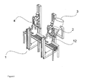
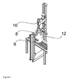
- the gas cylinder (12) advancing on the conveyor belt reaches the first station where the removal procedure (4) is performed and the gas cylinder is centered by the centering piston (9).
- the cylinder centering head (8) which is a pneumatic arm descends on top of the cylinder (12) and centers the cylinder (12).
- the removal piston (10) has a structure with a protrusion.
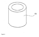
- the removal piston (10) on top of the cylinder (12) removes the gland rubber (11) from the mini-valve by the mechanism with protrusion.
- the mechanism with protrusion expands and holds the gland rubber (11) at multiple points and pulls up the held gland rubber (11) by using the pneumatic arm.
- the protrusions are then closed and drop the old gland rubber (11) into the accumulation tank located under the belt.
- the centering piston (9) is opened and the cylinder (12) starts advancing on the conveyor belt.
- the cylinder (12) reaching the installation system (2) is centered again by the centering piston (9).
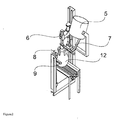
- the new gland rubber (11) is installed onto the mini-valve in the installation system (2).
- the centering head (8) descends onto the fixed cylinder (12).
- the centering head (8) is guided by a conical jig.
- the installation position of the new gland rubber (11) is precisely defined.
- the installation piston (6) installs the new gland rubber (11) to the mini-valve.
- the centering pistons (9) are opened and let the cylinder (12) advance on the conveyor belt.
- the installation system (2) is in relation with the feeding system (3).
- the feeding system (3) is comprised of the gland rubber chamber (5) where the new gland rubbers (11) are stored and the feeding rail (7).
- the feeding system (3) has a large capacity sufficient enough for the system.
- the installation system (2) takes the new gland rubber (11) from the feeding system (3).
- the new gland rubber (11) is transferred from the exit point of the feeding chamber (5) to the mouth of installation piston (6) on the installation system (2) by a rail (7). Then the installation procedure is performed.
Landscapes
- Engineering & Computer Science (AREA)
- Mechanical Engineering (AREA)
- Sealing Devices (AREA)
Claims (7)
- Système d'automatisation de caoutchouc d'étanchéité (1) permettant de changer automatiquement le caoutchouc d'étanchéité (11) qui est situé entre la soupape et le régulateur sur des cylindres à gaz ronds de type logement contenant du GPL et qui prévient les fuites, dans sa forme basique comprenant :- une chambre de caoutchouc d'étanchéité (5) qui stocke les nouveaux caoutchoucs d'étanchéité (11),- un piston d'installation (B) qui installe le nouveau caoutchouc d'étanchéité (11),- un rail (7) qui entraîne le caoutchouc d'étanchéité (11) vers le système d'installation,- une tête de centrage (8) qui ajuste la position d'installation et d'enlèvement du caoutchouc d'étanchéité (11) lors de l'installation du nouveau caoutchouc d'étanchéité (11) et de l'enlèvement de l'ancien caoutchouc d'étanchéité (11),- un groupe de pistons de centrage (9) qui centre le cylindre à gaz (12) lors de l'installation du nouveau caoutchouc d'étanchéité (11) et de l'enlèvement de l'ancien caoutchouc d'étanchéité (11).- un système d'installation (2) qui installe le caoutchouc d'étanchéité (11) sur le cylindre à gaz centré (12) et qui comprend et utilise le piston d'installation de caoutchouc d'étanchéité (6), la tête de centrage (8) et le piston de centrage (9) en combinaison,- un système d'alimentation (3) qui comprend la chambre de caoutchouc d'étanchéité (5) contenant les nouveaux caoutchoucs d'étanchéité (11) et le rail d'entraînement (7) qui transfère le caoutchouc d'étanchéité (11) au piston d'installation (6) et qui travaille conjointement avec le système d'installation (2),- un système d'enlèvement (4) qui comprend le piston d'enlèvement (10) ayant des protubérances et qui enlève l'ancien caoutchouc d'étanchéité (11).
- Système d'automatisation de caoutchouc d'étanchéité (1) selon la revendication 1, caractérisé par un piston d'enlèvement (10) avec des protubérances qui enlève le caoutchouc d'étanchéité (11) en descendant sur la mini-soupape et qui tient et comprime le caoutchouc d'étanchéité (11) par les protubérances.
- Système d'automatisation de caoutchouc d'étanchéité (1) selon la revendication 1, caractérisé par une chambre de caoutchouc d'étanchéité (5) qui stocke les nouveaux caoutchoucs d'étanchéité (11) et travaille en relation avec le système d'installation (2).
- Système d'automatisation de caoutchouc d'étanchéité (1) selon l'une quelconque des revendications précédentes, caractérisé par un rail d'entraînement de caoutchouc d'étanchéité (7) qui prélève le caoutchouc d'étanchéité (11) de la chambre d'alimentation (5) et le transfère vers le bec du piston d'installation (6).
- Système d'automatisation de caoutchouc d'étanchéité (1) selon l'une quelconque des revendications précédentes, caractérisé par un piston d'installation de caoutchouc d'étanchéité (6) qui reçoit le nouveau caoutchouc d'étanchéité (11) à travers le rail d'entraînement (7) et qui installe le caoutchouc d'étanchéité (11) sur la mini-soupape.
- Système d'automatisation de caoutchouc d'étanchéité (1) selon l'une quelconque des revendications précédentes, caractérisé par un piston de centrage de cylindre à gaz (9) qui fixe le cylindre à gaz (12) avançant sur la courroie de convoyeur lorsqu'elle atteint les systèmes d'enlèvement (4) ou d'installation (2) et permet ainsi un enlèvement et une installation faciles du caoutchouc d'étanchéité (11).
- Système d'automatisation de caoutchouc d'étanchéité (1) selon l'une quelconque des revendications précédentes, caractérisé par une tête de centrage de cylindre à gaz (8) qui descend sur le cylindre centré (12), qui définit précisément la position d'installation du caoutchouc d'étanchéité (11) et qui permet au piston d'installatien (6) de pouvoir installer le caoutchouc d'étanchéité (11) dans sa position en conséquence.
Applications Claiming Priority (1)
| Application Number | Priority Date | Filing Date | Title |
|---|---|---|---|
| TR200809549A TR200809549A2 (tr) | 2008-12-17 | 2008-12-17 | Bir boğaz lastiği otomasyon sistemi |
Publications (3)
| Publication Number | Publication Date |
|---|---|
| EP2199010A2 EP2199010A2 (fr) | 2010-06-23 |
| EP2199010A3 EP2199010A3 (fr) | 2011-12-28 |
| EP2199010B1 true EP2199010B1 (fr) | 2013-12-04 |
Family
ID=42110044
Family Applications (1)
| Application Number | Title | Priority Date | Filing Date |
|---|---|---|---|
| EP20090178675 Not-in-force EP2199010B1 (fr) | 2008-12-17 | 2009-12-10 | Système automatique pour remplacer un joint d'étanchéité en caoutchouc |
Country Status (3)
| Country | Link |
|---|---|
| EP (1) | EP2199010B1 (fr) |
| DK (1) | DK2199010T3 (fr) |
| TR (1) | TR200809549A2 (fr) |
Families Citing this family (6)
| Publication number | Priority date | Publication date | Assignee | Title |
|---|---|---|---|---|
| TR201007571A2 (tr) * | 2010-09-15 | 2012-04-24 | Aygaz Anoni̇m Şi̇rketi̇ | Bir lastik çıkarma makinası. |
| CN102489980B (zh) * | 2011-11-25 | 2013-07-03 | 长春工业大学 | 液化石油气瓶阀连接片装配工作台 |
| CN102672464B (zh) * | 2012-05-28 | 2014-05-21 | 南车株洲电力机车研究所有限公司 | 兆瓦级风力发电机组偏航制动器安装方法及辅助安装装置 |
| CN103537889B (zh) * | 2013-10-31 | 2016-04-13 | 维尔斯电子(昆山)有限公司 | 螺丝自动组装机 |
| CN111847364A (zh) * | 2019-04-29 | 2020-10-30 | 上海谷森医药有限公司 | 一种软雾吸入剂塑料瓶灌装压盖装置 |
| CN114833766A (zh) * | 2022-04-22 | 2022-08-02 | 中国煤炭地质总局第一水文地质队 | 一种胶活塞更换辅助装置 |
Family Cites Families (7)
| Publication number | Priority date | Publication date | Assignee | Title |
|---|---|---|---|---|
| US2380068A (en) * | 1943-12-08 | 1945-07-10 | Clark E Patton | Oil seal puller |
| FR2106646A5 (fr) * | 1970-09-18 | 1972-05-05 | Utilisation Ration Gaz | |
| US4612953A (en) * | 1985-04-19 | 1986-09-23 | Steven R. Zillig | Fluid coupling, seal removal tool and method |
| FR2683295B1 (fr) * | 1991-11-04 | 1994-03-04 | Butagaz | Appareil de pose automatique d'un joint dans le nez de robinet d'une bouteille de gaz. |
| ES2130896B1 (es) * | 1995-12-22 | 2000-02-16 | Repsol Butano Sa | Maquina colocadora de precintos, preferentemente en envases contenedores de gases a presion. |
| ES2148054B1 (es) * | 1997-11-27 | 2001-04-16 | Repsol Butano Sa | Maquina colocadora de tapones-precinto. |
| FR2859199B1 (fr) * | 2003-08-29 | 2007-01-05 | Newtec Internat Group | Installation de soufflage et de remplissage de bouteilles en matiere plastique |
-
2008
- 2008-12-17 TR TR200809549A patent/TR200809549A2/xx unknown
-
2009
- 2009-12-10 EP EP20090178675 patent/EP2199010B1/fr not_active Not-in-force
- 2009-12-10 DK DK09178675T patent/DK2199010T3/en active
Also Published As
| Publication number | Publication date |
|---|---|
| EP2199010A3 (fr) | 2011-12-28 |
| TR200809549A2 (tr) | 2010-07-21 |
| DK2199010T3 (en) | 2014-03-03 |
| EP2199010A2 (fr) | 2010-06-23 |
Similar Documents
| Publication | Publication Date | Title |
|---|---|---|
| EP2199010B1 (fr) | Système automatique pour remplacer un joint d'étanchéité en caoutchouc | |
| CN114057145A (zh) | 用于容器的填充-密封单元的密封性控制的方法以及填充-密封机 | |
| US4899899A (en) | Pressure vessel | |
| RU2011113760A (ru) | Способ и устройство в системе пневматического транспортирования материала | |
| JP2011246721A (ja) | 炭化水素を含有する製品を処理する方法及び装置 | |
| CN114055116A (zh) | 一种空气弹簧原拆原装检测检修方法 | |
| CN101873988A (zh) | 加工容器密封的设备及方法 | |
| ATE516461T1 (de) | Verschlusseinrichtung zum dichten verschliessen eines füll- und entleerungssystems von eisenbahnkesselwagen oder transporttanks | |
| DE69505802D1 (de) | Schutzbehälter für die unterirdische Installation von Tanks für Flüssiggas unter Druck | |
| US20170138498A1 (en) | Valve pressure assembly and methods of operating the same | |
| KR102095689B1 (ko) | 가스 엔진 파워 플랜트의 배기 연료 처리 조립체 및 가스 엔진 파워 플랜트로부터 배기 연료 가스를 회수하는 방법 | |
| BR0313947A (pt) | Método de teste de integridade de fechamento para operação de engarrafamento de enchimento a quente | |
| FI92250B (fi) | Menetelmä ja laitteisto aineen syöttämiseksi paineistettuun tilaan | |
| KR101599611B1 (ko) | 공압식 자동 수위조절 씰포트 | |
| EP4371926A1 (fr) | Système et procédé de détection d'anomalie liée à une paroi de séparation pour remplissage aseptique, et procédé de production d'un système de remplissage aseptique | |
| FR2841335B1 (fr) | Procede de controle de l'etancheite d'un reservoir d'un aeronef et dispositif associe pour equiper ces reservoirs | |
| PT919516E (pt) | Maquinas de instalacao de tampas de vedacao | |
| CN105253480A (zh) | 一种油泵房油气排放装置和使用其的油气排放方法 | |
| JP5354919B2 (ja) | 空気配管の漏気箇所判定方法 | |
| CN214987591U (zh) | 一种具有检测功能的储油罐 | |
| KR101324379B1 (ko) | 가스홀더 비상방산관의 수봉 장치 및 이를 이용한 수봉 방법 | |
| CN201194009Y (zh) | 用于喷气燃料抗氧剂性能评定的加速储存试验装置 | |
| CN115452268B (zh) | 一种lng船可燃气体探测系统隔离阀箱及其气密性检测方法 | |
| CN205424273U (zh) | 一种用于泄露法兰封堵的新型卡具 | |
| SU1078180A1 (ru) | Способ локализации участка трубопровода |
Legal Events
| Date | Code | Title | Description |
|---|---|---|---|
| PUAI | Public reference made under article 153(3) epc to a published international application that has entered the european phase |
Free format text: ORIGINAL CODE: 0009012 |
|
| AK | Designated contracting states |
Kind code of ref document: A2 Designated state(s): AT BE BG CH CY CZ DE DK EE ES FI FR GB GR HR HU IE IS IT LI LT LU LV MC MK MT NL NO PL PT RO SE SI SK SM TR |
|
| AX | Request for extension of the european patent |
Extension state: AL BA RS |
|
| PUAL | Search report despatched |
Free format text: ORIGINAL CODE: 0009013 |
|
| AK | Designated contracting states |
Kind code of ref document: A3 Designated state(s): AT BE BG CH CY CZ DE DK EE ES FI FR GB GR HR HU IE IS IT LI LT LU LV MC MK MT NL NO PL PT RO SE SI SK SM TR |
|
| AX | Request for extension of the european patent |
Extension state: AL BA RS |
|
| RIC1 | Information provided on ipc code assigned before grant |
Ipc: F17C 5/00 20060101ALI20111121BHEP Ipc: B23P 19/00 20060101AFI20111121BHEP Ipc: B23P 19/02 20060101ALI20111121BHEP Ipc: B67B 3/00 20060101ALI20111121BHEP Ipc: B23P 19/08 20060101ALI20111121BHEP |
|
| 17P | Request for examination filed |
Effective date: 20120626 |
|
| GRAP | Despatch of communication of intention to grant a patent |
Free format text: ORIGINAL CODE: EPIDOSNIGR1 |
|
| INTG | Intention to grant announced |
Effective date: 20130902 |
|
| GRAS | Grant fee paid |
Free format text: ORIGINAL CODE: EPIDOSNIGR3 |
|
| GRAA | (expected) grant |
Free format text: ORIGINAL CODE: 0009210 |
|
| AK | Designated contracting states |
Kind code of ref document: B1 Designated state(s): AT BE BG CH CY CZ DE DK EE ES FI FR GB GR HR HU IE IS IT LI LT LU LV MC MK MT NL NO PL PT RO SE SI SK SM TR |
|
| REG | Reference to a national code |
Ref country code: GB Ref legal event code: FG4D |
|
| REG | Reference to a national code |
Ref country code: CH Ref legal event code: EP |
|
| REG | Reference to a national code |
Ref country code: AT Ref legal event code: REF Ref document number: 643323 Country of ref document: AT Kind code of ref document: T Effective date: 20140115 Ref country code: IE Ref legal event code: FG4D |
|
| REG | Reference to a national code |
Ref country code: DE Ref legal event code: R096 Ref document number: 602009020485 Country of ref document: DE Effective date: 20140130 |
|
| REG | Reference to a national code |
Ref country code: DK Ref legal event code: T3 Effective date: 20140228 |
|
| REG | Reference to a national code |
Ref country code: NL Ref legal event code: VDEP Effective date: 20131204 |
|
| REG | Reference to a national code |
Ref country code: AT Ref legal event code: MK05 Ref document number: 643323 Country of ref document: AT Kind code of ref document: T Effective date: 20131204 |
|
| PG25 | Lapsed in a contracting state [announced via postgrant information from national office to epo] |
Ref country code: SE Free format text: LAPSE BECAUSE OF FAILURE TO SUBMIT A TRANSLATION OF THE DESCRIPTION OR TO PAY THE FEE WITHIN THE PRESCRIBED TIME-LIMIT Effective date: 20131204 Ref country code: LT Free format text: LAPSE BECAUSE OF FAILURE TO SUBMIT A TRANSLATION OF THE DESCRIPTION OR TO PAY THE FEE WITHIN THE PRESCRIBED TIME-LIMIT Effective date: 20131204 Ref country code: HR Free format text: LAPSE BECAUSE OF FAILURE TO SUBMIT A TRANSLATION OF THE DESCRIPTION OR TO PAY THE FEE WITHIN THE PRESCRIBED TIME-LIMIT Effective date: 20131204 Ref country code: NL Free format text: LAPSE BECAUSE OF FAILURE TO SUBMIT A TRANSLATION OF THE DESCRIPTION OR TO PAY THE FEE WITHIN THE PRESCRIBED TIME-LIMIT Effective date: 20131204 Ref country code: FI Free format text: LAPSE BECAUSE OF FAILURE TO SUBMIT A TRANSLATION OF THE DESCRIPTION OR TO PAY THE FEE WITHIN THE PRESCRIBED TIME-LIMIT Effective date: 20131204 Ref country code: NO Free format text: LAPSE BECAUSE OF FAILURE TO SUBMIT A TRANSLATION OF THE DESCRIPTION OR TO PAY THE FEE WITHIN THE PRESCRIBED TIME-LIMIT Effective date: 20140304 |
|
| REG | Reference to a national code |
Ref country code: LT Ref legal event code: MG4D |
|
| PG25 | Lapsed in a contracting state [announced via postgrant information from national office to epo] |
Ref country code: AT Free format text: LAPSE BECAUSE OF FAILURE TO SUBMIT A TRANSLATION OF THE DESCRIPTION OR TO PAY THE FEE WITHIN THE PRESCRIBED TIME-LIMIT Effective date: 20131204 Ref country code: LV Free format text: LAPSE BECAUSE OF FAILURE TO SUBMIT A TRANSLATION OF THE DESCRIPTION OR TO PAY THE FEE WITHIN THE PRESCRIBED TIME-LIMIT Effective date: 20131204 Ref country code: CY Free format text: LAPSE BECAUSE OF FAILURE TO SUBMIT A TRANSLATION OF THE DESCRIPTION OR TO PAY THE FEE WITHIN THE PRESCRIBED TIME-LIMIT Effective date: 20131204 |
|
| REG | Reference to a national code |
Ref country code: DE Ref legal event code: R119 Ref document number: 602009020485 Country of ref document: DE |
|
| PG25 | Lapsed in a contracting state [announced via postgrant information from national office to epo] |
Ref country code: IS Free format text: LAPSE BECAUSE OF FAILURE TO SUBMIT A TRANSLATION OF THE DESCRIPTION OR TO PAY THE FEE WITHIN THE PRESCRIBED TIME-LIMIT Effective date: 20140404 Ref country code: EE Free format text: LAPSE BECAUSE OF FAILURE TO SUBMIT A TRANSLATION OF THE DESCRIPTION OR TO PAY THE FEE WITHIN THE PRESCRIBED TIME-LIMIT Effective date: 20131204 Ref country code: BE Free format text: LAPSE BECAUSE OF FAILURE TO SUBMIT A TRANSLATION OF THE DESCRIPTION OR TO PAY THE FEE WITHIN THE PRESCRIBED TIME-LIMIT Effective date: 20131204 |
|
| REG | Reference to a national code |
Ref country code: CH Ref legal event code: PL |
|
| PG25 | Lapsed in a contracting state [announced via postgrant information from national office to epo] |
Ref country code: RO Free format text: LAPSE BECAUSE OF FAILURE TO SUBMIT A TRANSLATION OF THE DESCRIPTION OR TO PAY THE FEE WITHIN THE PRESCRIBED TIME-LIMIT Effective date: 20131204 Ref country code: CZ Free format text: LAPSE BECAUSE OF FAILURE TO SUBMIT A TRANSLATION OF THE DESCRIPTION OR TO PAY THE FEE WITHIN THE PRESCRIBED TIME-LIMIT Effective date: 20131204 Ref country code: PL Free format text: LAPSE BECAUSE OF FAILURE TO SUBMIT A TRANSLATION OF THE DESCRIPTION OR TO PAY THE FEE WITHIN THE PRESCRIBED TIME-LIMIT Effective date: 20131204 Ref country code: ES Free format text: LAPSE BECAUSE OF FAILURE TO SUBMIT A TRANSLATION OF THE DESCRIPTION OR TO PAY THE FEE WITHIN THE PRESCRIBED TIME-LIMIT Effective date: 20131204 Ref country code: SK Free format text: LAPSE BECAUSE OF FAILURE TO SUBMIT A TRANSLATION OF THE DESCRIPTION OR TO PAY THE FEE WITHIN THE PRESCRIBED TIME-LIMIT Effective date: 20131204 Ref country code: PT Free format text: LAPSE BECAUSE OF FAILURE TO SUBMIT A TRANSLATION OF THE DESCRIPTION OR TO PAY THE FEE WITHIN THE PRESCRIBED TIME-LIMIT Effective date: 20140404 |
|
| REG | Reference to a national code |
Ref country code: DE Ref legal event code: R119 Ref document number: 602009020485 Country of ref document: DE Effective date: 20140701 |
|
| REG | Reference to a national code |
Ref country code: IE Ref legal event code: MM4A |
|
| PG25 | Lapsed in a contracting state [announced via postgrant information from national office to epo] |
Ref country code: MC Free format text: LAPSE BECAUSE OF FAILURE TO SUBMIT A TRANSLATION OF THE DESCRIPTION OR TO PAY THE FEE WITHIN THE PRESCRIBED TIME-LIMIT Effective date: 20131204 |
|
| PLBE | No opposition filed within time limit |
Free format text: ORIGINAL CODE: 0009261 |
|
| STAA | Information on the status of an ep patent application or granted ep patent |
Free format text: STATUS: NO OPPOSITION FILED WITHIN TIME LIMIT |
|
| PG25 | Lapsed in a contracting state [announced via postgrant information from national office to epo] |
Ref country code: CH Free format text: LAPSE BECAUSE OF NON-PAYMENT OF DUE FEES Effective date: 20131231 Ref country code: IE Free format text: LAPSE BECAUSE OF NON-PAYMENT OF DUE FEES Effective date: 20131210 Ref country code: DE Free format text: LAPSE BECAUSE OF NON-PAYMENT OF DUE FEES Effective date: 20140701 Ref country code: LI Free format text: LAPSE BECAUSE OF NON-PAYMENT OF DUE FEES Effective date: 20131231 |
|
| 26N | No opposition filed |
Effective date: 20140905 |
|
| GBPC | Gb: european patent ceased through non-payment of renewal fee |
Effective date: 20140304 |
|
| PG25 | Lapsed in a contracting state [announced via postgrant information from national office to epo] |
Ref country code: GB Free format text: LAPSE BECAUSE OF NON-PAYMENT OF DUE FEES Effective date: 20140304 |
|
| PG25 | Lapsed in a contracting state [announced via postgrant information from national office to epo] |
Ref country code: SI Free format text: LAPSE BECAUSE OF FAILURE TO SUBMIT A TRANSLATION OF THE DESCRIPTION OR TO PAY THE FEE WITHIN THE PRESCRIBED TIME-LIMIT Effective date: 20131204 |
|
| PG25 | Lapsed in a contracting state [announced via postgrant information from national office to epo] |
Ref country code: SM Free format text: LAPSE BECAUSE OF FAILURE TO SUBMIT A TRANSLATION OF THE DESCRIPTION OR TO PAY THE FEE WITHIN THE PRESCRIBED TIME-LIMIT Effective date: 20131204 |
|
| PG25 | Lapsed in a contracting state [announced via postgrant information from national office to epo] |
Ref country code: TR Free format text: LAPSE BECAUSE OF FAILURE TO SUBMIT A TRANSLATION OF THE DESCRIPTION OR TO PAY THE FEE WITHIN THE PRESCRIBED TIME-LIMIT Effective date: 20131204 |
|
| PG25 | Lapsed in a contracting state [announced via postgrant information from national office to epo] |
Ref country code: MK Free format text: LAPSE BECAUSE OF FAILURE TO SUBMIT A TRANSLATION OF THE DESCRIPTION OR TO PAY THE FEE WITHIN THE PRESCRIBED TIME-LIMIT Effective date: 20131204 Ref country code: BG Free format text: LAPSE BECAUSE OF FAILURE TO SUBMIT A TRANSLATION OF THE DESCRIPTION OR TO PAY THE FEE WITHIN THE PRESCRIBED TIME-LIMIT Effective date: 20131204 Ref country code: HU Free format text: LAPSE BECAUSE OF FAILURE TO SUBMIT A TRANSLATION OF THE DESCRIPTION OR TO PAY THE FEE WITHIN THE PRESCRIBED TIME-LIMIT; INVALID AB INITIO Effective date: 20091210 Ref country code: LU Free format text: LAPSE BECAUSE OF NON-PAYMENT OF DUE FEES Effective date: 20131210 |
|
| PG25 | Lapsed in a contracting state [announced via postgrant information from national office to epo] |
Ref country code: GR Free format text: LAPSE BECAUSE OF NON-PAYMENT OF DUE FEES Effective date: 20131204 Ref country code: MT Free format text: LAPSE BECAUSE OF FAILURE TO SUBMIT A TRANSLATION OF THE DESCRIPTION OR TO PAY THE FEE WITHIN THE PRESCRIBED TIME-LIMIT Effective date: 20131204 |
|
| REG | Reference to a national code |
Ref country code: FR Ref legal event code: PLFP Year of fee payment: 7 |
|
| PG25 | Lapsed in a contracting state [announced via postgrant information from national office to epo] |
Ref country code: GR Free format text: LAPSE BECAUSE OF FAILURE TO SUBMIT A TRANSLATION OF THE DESCRIPTION OR TO PAY THE FEE WITHIN THE PRESCRIBED TIME-LIMIT Effective date: 20140305 |
|
| REG | Reference to a national code |
Ref country code: FR Ref legal event code: PLFP Year of fee payment: 8 |
|
| REG | Reference to a national code |
Ref country code: FR Ref legal event code: PLFP Year of fee payment: 9 |
|
| PGFP | Annual fee paid to national office [announced via postgrant information from national office to epo] |
Ref country code: IT Payment date: 20181220 Year of fee payment: 10 |
|
| PGFP | Annual fee paid to national office [announced via postgrant information from national office to epo] |
Ref country code: FR Payment date: 20191220 Year of fee payment: 11 Ref country code: DK Payment date: 20191227 Year of fee payment: 11 |
|
| PG25 | Lapsed in a contracting state [announced via postgrant information from national office to epo] |
Ref country code: IT Free format text: LAPSE BECAUSE OF NON-PAYMENT OF DUE FEES Effective date: 20191210 |
|
| REG | Reference to a national code |
Ref country code: DK Ref legal event code: EBP Effective date: 20201231 |
|
| PG25 | Lapsed in a contracting state [announced via postgrant information from national office to epo] |
Ref country code: FR Free format text: LAPSE BECAUSE OF NON-PAYMENT OF DUE FEES Effective date: 20201231 |
|
| PG25 | Lapsed in a contracting state [announced via postgrant information from national office to epo] |
Ref country code: DK Free format text: LAPSE BECAUSE OF NON-PAYMENT OF DUE FEES Effective date: 20201231 |