EP2199017A1 - Concept de machines produisant peu de vibrations - Google Patents
Concept de machines produisant peu de vibrations Download PDFInfo
- Publication number
- EP2199017A1 EP2199017A1 EP08171934A EP08171934A EP2199017A1 EP 2199017 A1 EP2199017 A1 EP 2199017A1 EP 08171934 A EP08171934 A EP 08171934A EP 08171934 A EP08171934 A EP 08171934A EP 2199017 A1 EP2199017 A1 EP 2199017A1
- Authority
- EP
- European Patent Office
- Prior art keywords
- machine
- machine bed
- locking device
- sanding unit
- grinding
- Prior art date
- Legal status (The legal status is an assumption and is not a legal conclusion. Google has not performed a legal analysis and makes no representation as to the accuracy of the status listed.)
- Granted
Links
- 230000010355 oscillation Effects 0.000 title 1
- 238000000034 method Methods 0.000 claims abstract description 5
- 238000003754 machining Methods 0.000 claims description 6
- 238000004891 communication Methods 0.000 claims description 4
- 239000002023 wood Substances 0.000 claims description 4
- 239000000463 material Substances 0.000 claims description 3
- 239000011372 high-strength concrete Substances 0.000 claims description 2
- 239000002184 metal Substances 0.000 claims description 2
- 239000004033 plastic Substances 0.000 claims description 2
- 238000010924 continuous production Methods 0.000 description 1
- 230000001419 dependent effect Effects 0.000 description 1
- 230000000694 effects Effects 0.000 description 1
- 230000002349 favourable effect Effects 0.000 description 1
- 230000008092 positive effect Effects 0.000 description 1
- 238000003860 storage Methods 0.000 description 1
Images


Classifications
-
- B—PERFORMING OPERATIONS; TRANSPORTING
- B24—GRINDING; POLISHING
- B24B—MACHINES, DEVICES, OR PROCESSES FOR GRINDING OR POLISHING; DRESSING OR CONDITIONING OF ABRADING SURFACES; FEEDING OF GRINDING, POLISHING, OR LAPPING AGENTS
- B24B21/00—Machines or devices using grinding or polishing belts; Accessories therefor
- B24B21/04—Machines or devices using grinding or polishing belts; Accessories therefor for grinding plane surfaces
-
- B—PERFORMING OPERATIONS; TRANSPORTING
- B24—GRINDING; POLISHING
- B24B—MACHINES, DEVICES, OR PROCESSES FOR GRINDING OR POLISHING; DRESSING OR CONDITIONING OF ABRADING SURFACES; FEEDING OF GRINDING, POLISHING, OR LAPPING AGENTS
- B24B21/00—Machines or devices using grinding or polishing belts; Accessories therefor
- B24B21/18—Accessories
- B24B21/20—Accessories for controlling or adjusting the tracking or the tension of the grinding belt
-
- B—PERFORMING OPERATIONS; TRANSPORTING
- B24—GRINDING; POLISHING
- B24B—MACHINES, DEVICES, OR PROCESSES FOR GRINDING OR POLISHING; DRESSING OR CONDITIONING OF ABRADING SURFACES; FEEDING OF GRINDING, POLISHING, OR LAPPING AGENTS
- B24B41/00—Component parts such as frames, beds, carriages, headstocks
- B24B41/007—Weight compensation; Temperature compensation; Vibration damping
-
- B—PERFORMING OPERATIONS; TRANSPORTING
- B24—GRINDING; POLISHING
- B24B—MACHINES, DEVICES, OR PROCESSES FOR GRINDING OR POLISHING; DRESSING OR CONDITIONING OF ABRADING SURFACES; FEEDING OF GRINDING, POLISHING, OR LAPPING AGENTS
- B24B7/00—Machines or devices designed for grinding plane surfaces on work, including polishing plane glass surfaces; Accessories therefor
- B24B7/06—Machines or devices designed for grinding plane surfaces on work, including polishing plane glass surfaces; Accessories therefor involving conveyor belts, a sequence of travelling work-tables or the like
Definitions
- the present invention relates to a grinding unit for processing substantially plate-shaped workpieces, the workpieces preferably at least partially made of wood, wood-based materials, plastic, metal or a combination thereof.
- a grinding unit is used in particular in the refinement of workpiece surfaces of such workpieces.
- EP 1 669 163 A1 a grinding unit, which has an endless grinding belt for machining workpieces.
- a roller is rotatably mounted on the machine head, and is driven by a likewise mounted on the machine head drive means.
- lifting means are provided for lifting the roller.
- grinding machines according to this and further prior art have the disadvantage that the machine upper part is exposed to strong vibrations, which in turn influence the grinding result.
- the surface structure of a workpiece to be machined thus depends inter alia also on vibrations of the grinding aggregate which result from the operating state of the aggregate.
- the present invention is thus also intended to ensure exact controllability of the processing result and the associated reproducibility.
- the invention is based on the idea to design a grinding unit in such a way that vibrations of the machine head can be avoided or derived in a favorable manner.
- the present invention provides a grinding unit comprising: a machine bed having a workpiece support surface, an engine top communicating with the machine bed, the machine top being movable in a direction substantially perpendicular to the workpiece support surface, and drive means for driving an abrasive, in particular an electric motor.
- the grinding unit according to the invention is characterized in that the drive means is fixed to the machine bed.
- the machine bed is commonly formed in a processing machine as the grinding unit according to the invention as a rigid body with high mass.
- the on the machine bed fastened machine head is thus stimulated to a much lesser extent by the drive means than was the case with a directly attached to the machine head drive means. Consequently, the present grinding unit can reduce the vibrations of the machine head, which in turn has a positive effect on the machining result and its targeted influence.
- the grinding unit according to the invention is characterized in that the movable machine head can be fixed by means of a locking device with respect to the machine bed.
- the machine head can be selectively fixed at the time of processing on the machine bed, while the mobility of the machine head is ensured in a direction substantially perpendicular to the workpiece support surface direction to the machine bed after releasing the locking device.
- the locking device can thus be controlled specifically and in accordance with the adjustment of the machine head and / or the grinding drive.
- the flexibility of the grinding unit is guaranteed with respect to different workpiece thicknesses.
- a system can be connected to the grinding unit, with which the respective workpiece thickness can be detected, and accordingly the adjustment of the machine head and the locking device can be controlled.
- the abrasive means driven by the drive means is a circulating belt grinding means. With this larger areas of plate-shaped workpieces can be processed evenly in continuous operation.
- the grinding unit according to the invention can be characterized in that the machine head is guided relative to the machine bed in a linear guide. Consequently, the stepless adjustability of the machine head relative to the machine bed in a vertical direction can be ensured, and the machine head can be adjusted according to the workpiece thickness of the plate-shaped workpiece to be worked.
- the grinding unit is characterized in that the drive means is in communication with the abrasive via a belt to drive the abrasive. In this way it can be ensured that the drive means is fixed to the machine bed, but at the same time can drive an abrasive located on the machine upper part.
- a grinding unit according to the invention is characterized in that the belt is guided over an adjustable deflection roller, wherein the deflection roller can be adjusted in accordance with a movement of the machine upper part to ensure a sufficient belt tension. Consequently, according to this embodiment of the invention, a continuous production of the machine head with respect to the machine bed can be carried out while the belt tension is always the same. Guiding the belt over a pulley is a relatively simple structural measure to achieve the objects of the present invention.
- a grinding unit according to this embodiment provides a variable system, which, however, can be realized structurally in a simple manner.
- the grinding unit is characterized in that the workpiece support surface has a conveyor belt, which conveyor belt is guided over rollers fixed to the machine bed.
- the grinding unit according to the invention is suitable for a continuous operation, so that high quantities can be processed.
- a grinding unit may be characterized in that the locking device used is a pneumatic brake. This can then be controlled to determine the machine head with respect to the machine bed according to flexible and targeted, to exert a braking effect or in turn to solve them.
- the locking device used is a pneumatic brake. This can then be controlled to determine the machine head with respect to the machine bed according to flexible and targeted, to exert a braking effect or in turn to solve them.
- the locking device is attached to the machine bed and can be guided or detected along a guide element attached to the machine head.
- the locking device can perform a locking movement in a plane parallel to the workpiece support surface.
- the machine head can be moved with respect to the machine bed in a vertical direction, wherein the movement of the machine head is substantially perpendicular to the direction of the braking force of the locking device.
- the locking device has a clamping device which is preferably guided in a groove provided on the guide element.
- a clamping device which is preferably guided in a groove provided on the guide element.
- the locking device may comprise a guide pin which is guided in a groove provided in the guide element. In this way, an additional guide for the relative movement between the machine head and machine bed is provided.
- the grinding unit is characterized in that the machine bed consists at least in sections of a high-strength concrete and is preferably made in one piece.
- Such a machine bed contributes in a special way to avoid vibrations of the machine head and is therefore particularly suitable for achieving the objectives of the present invention.
- the machine bed can also be made of a cast material without departing from the basic idea of the present invention.
- Fig. 1 shows an embodiment of a grinding unit 1 with two abrasive belts 21, 22 in a partially sectioned view.
- the grinding unit 1 in this case has a machine bed 2, as well as a machine head 3 mounted in the vertical direction above.
- the machine head 3 is movable relative to the machine bed 2 (indicated by arrows).
- FIG. 1 schematically to recognize holes 42 per drive means 4, which extend in a vertical direction and in which screw connections, not shown, can be screwed to fix the drive means 4 on the machine bed 2.
- the drive means 4 have an engine body 43 and a drive pulley 41, wherein the axes 44 of the drive pulleys 41 extend in a horizontal direction transversely to the feed direction of the workpieces to be machined explained in more detail later.
- a belt 5 is wound, which is driven via the respective drive pulley 41.
- two belts 5 are provided for driving the two abrasive belts 21, 22.
- the belt 5 is further guided over the deflecting rollers 6a and 6b attached to the machine bed 2, and drives the machine upper part 4 mounted roller 8 and the rollers 8a and 8b.
- the axes of rotation of all said rollers 6a, 6b, 8, 8a, 8b run in a substantially horizontal direction, and are aligned substantially parallel to the axis 44 of the corresponding drive pulley 44.
- Fig. 1 the embodiment of a grinding machine with two abrasive belts 21, 22 is shown. These sanding belts 21, 22 are guided between the roller 8 driven by the belt 5 and the driven rollers 8a, 8b and a respective deflecting roller 32 arranged above it. All rollers for guiding the abrasive belts 21, 22 are attached to the machine head 3.
- the belt 5 can always be kept in the tensioned state by adjusting the deflection roller 6a.
- the storage of the adjustable guide roller 6a may be provided with a dynamometer to always ensure sufficient tension of the drive belt.
- the described adjustability of the machine upper part 3 relative to the machine bed 2 is carried out by means of a mechanical adjusting device 9.
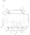
- a mechanical adjusting device 9 Like the top view in Fig. 2 can be seen, four mechanical adjusting devices 9 are provided for adjusting the machine head 3. These are driven in each case via a connected to the machine bed 2 and arranged below this angle gear 9a.
- the grinding unit 1 of the present embodiment a conveyor belt 10, which serves as a workpiece support surface.
- the conveyor belt 10 is guided and driven at the entrance area or at the end area of the grinding unit 1 by means of rollers 10a, 10b. Through this structure, a continuous processing is possible.
- the grinding unit 1 further comprises a total of four locking devices 7, two each on one side of the conveyor belt 10.
- a locking device 7 is in Fig. 3 shown in a schematic side view.
- the locking device 7 of the present embodiment a pneumatic brake, has a brake body 71 formed in the shape of a rectangular cube.
- the machine head 3 along a vertically extending groove 32 relative to the attached to the machine bed 2 locking device 7 is movable.
- the vertical groove 32 extends within a guide element 31 connected to the machine upper part 3.
- at least one pin 72 is provided on the locking device 7 and is guided in the vertical groove 32.
- the braking force is perpendicular to the plane of the drawing shown.
- the grinding unit 1 can be operated as follows. By means of a measuring device, the thickness of a component is determined, and passed the detected value to a control unit. Subsequently, the machine head 1 3 is moved relative to the machine bed 2, so that the distance between the sanding belt / sanding belts and the conveyor belt 10 is adjusted according to the processing. Subsequently, the machine head 3 is firmly connected by means of the locking device 7 with the machine bed 2.
- the workpiece to be machined is moved by means of the conveyor belt 10 after loading in the direction of the grinding belt / belts, and the processing is performed. Subsequently, the workpiece is again conveyed out of the processing area, and can be removed manually or mechanically at the end of the conveyor belt.
- the locking device 7 is released so that the machine upper part 3 in turn can be moved relative to the machine bed 2.
Landscapes
- Engineering & Computer Science (AREA)
- Mechanical Engineering (AREA)
- Finish Polishing, Edge Sharpening, And Grinding By Specific Grinding Devices (AREA)
Priority Applications (3)
| Application Number | Priority Date | Filing Date | Title |
|---|---|---|---|
| EP08171934A EP2199017B1 (fr) | 2008-12-17 | 2008-12-17 | Concept de machines produisant peu de vibrations |
| ES08171934T ES2378172T3 (es) | 2008-12-17 | 2008-12-17 | Concepto de máquina de baja vibración |
| PL08171934T PL2199017T3 (pl) | 2008-12-17 | 2008-12-17 | Koncepcja maszyny o niskim poziomie drgań |
Applications Claiming Priority (1)
| Application Number | Priority Date | Filing Date | Title |
|---|---|---|---|
| EP08171934A EP2199017B1 (fr) | 2008-12-17 | 2008-12-17 | Concept de machines produisant peu de vibrations |
Publications (2)
| Publication Number | Publication Date |
|---|---|
| EP2199017A1 true EP2199017A1 (fr) | 2010-06-23 |
| EP2199017B1 EP2199017B1 (fr) | 2011-11-30 |
Family
ID=40677718
Family Applications (1)
| Application Number | Title | Priority Date | Filing Date |
|---|---|---|---|
| EP08171934A Not-in-force EP2199017B1 (fr) | 2008-12-17 | 2008-12-17 | Concept de machines produisant peu de vibrations |
Country Status (3)
| Country | Link |
|---|---|
| EP (1) | EP2199017B1 (fr) |
| ES (1) | ES2378172T3 (fr) |
| PL (1) | PL2199017T3 (fr) |
Cited By (1)
| Publication number | Priority date | Publication date | Assignee | Title |
|---|---|---|---|---|
| CN107322402A (zh) * | 2017-08-31 | 2017-11-07 | 凯里市浪金科技有限责任公司 | 一种钣金研磨机 |
Citations (2)
| Publication number | Priority date | Publication date | Assignee | Title |
|---|---|---|---|---|
| US6089958A (en) * | 1999-05-13 | 2000-07-18 | Costa; Alessandro | Belt sander with orbitally translated abrasive belt |
| EP1669163A1 (fr) | 2004-12-10 | 2006-06-14 | SCM GROUP S.p.A. | Procédé et dispositif pour le meulage de panneaux en bois |
-
2008
- 2008-12-17 PL PL08171934T patent/PL2199017T3/pl unknown
- 2008-12-17 ES ES08171934T patent/ES2378172T3/es active Active
- 2008-12-17 EP EP08171934A patent/EP2199017B1/fr not_active Not-in-force
Patent Citations (2)
| Publication number | Priority date | Publication date | Assignee | Title |
|---|---|---|---|---|
| US6089958A (en) * | 1999-05-13 | 2000-07-18 | Costa; Alessandro | Belt sander with orbitally translated abrasive belt |
| EP1669163A1 (fr) | 2004-12-10 | 2006-06-14 | SCM GROUP S.p.A. | Procédé et dispositif pour le meulage de panneaux en bois |
Cited By (1)
| Publication number | Priority date | Publication date | Assignee | Title |
|---|---|---|---|---|
| CN107322402A (zh) * | 2017-08-31 | 2017-11-07 | 凯里市浪金科技有限责任公司 | 一种钣金研磨机 |
Also Published As
| Publication number | Publication date |
|---|---|
| PL2199017T3 (pl) | 2012-04-30 |
| ES2378172T3 (es) | 2012-04-09 |
| EP2199017B1 (fr) | 2011-11-30 |
Similar Documents
| Publication | Publication Date | Title |
|---|---|---|
| DE3432549A1 (de) | Kontinuierlich arbeitende presse zum verpressen von spanplattenbahnen, faserplattenbahnen u.dgl. pressgutbahnen | |
| DE102011116842A1 (de) | Schleifvorrichtung | |
| EP1990133B1 (fr) | Agrégat de ponçage comme outil pour un dispositif de traitement | |
| DE20319366U1 (de) | Durchlaufschleifmaschine zum Bearbeiten einer ebenen Werkstückoberfläche | |
| EP0455142A2 (fr) | Machine à meuler des profilés | |
| EP3459679A1 (fr) | Dispositif de production d'un finissage non défini sur une surface d'une pièce à usiner métallique dans un processus en continu | |
| DE19723306C2 (de) | Verfahren und Vorrichtung zum Schleifen oder Polieren von Stirnflächen plattenförmiger Körper | |
| DE102017101141A1 (de) | Vorrichtung und Verfahren zum Schleifen und Polieren | |
| DE69834953T2 (de) | Vorschubwalze | |
| DE1658304C3 (de) | Maschine zum Abschleifen des Schweißgrates von stumpfgeschweißten, nichtverlegten Schienen | |
| EP1615757B1 (fr) | Presse et procede de production de panneaux | |
| DD256612A3 (de) | Druckbalken fuer langbandschleifmaschine | |
| EP2199017B1 (fr) | Concept de machines produisant peu de vibrations | |
| EP3336019B1 (fr) | Appareil d'ajustage | |
| DE10053410C1 (de) | Schleifanlage und Verfahren zum differenzierten Schleifen einer mit einem leitfähigem Material beschichteten Platte für Leiterplatinen | |
| EP2527116B1 (fr) | Presse continue et procédé utilisant une telle press | |
| EP1918458B1 (fr) | Dispositif de meulage de profilés avec une bande abrasive en rotation | |
| WO2024208738A1 (fr) | Système de transport pour des pièces à travailler et procédé permettant de faire fonctionner un système de transport | |
| DE19828824C2 (de) | Verfahren und Presse zum kontinuierlichen Betrieb im Zuge der Herstellung von Spanplatten, Laminatplatten o. dgl. | |
| EP0571816B1 (fr) | Machine de collage des cÔtés avec dispositif d'affleurage de champs | |
| DE3109427C2 (fr) | ||
| DE19810574B4 (de) | Vorrichtung zur Betätigung von Pressen in Klemmeinrichtungen für den Zusammenbau von Möbelstücken | |
| DE10326455B4 (de) | Falzmesserantrieb einer Falzmaschine | |
| DE9116502U1 (de) | Abtafelmaschine zum Abtafeln einer kontinuierlich zugeführten Warenbahn | |
| EP1486445B1 (fr) | Dispositif d'entraînement de la lame de pliage d'une machine à plier |
Legal Events
| Date | Code | Title | Description |
|---|---|---|---|
| PUAI | Public reference made under article 153(3) epc to a published international application that has entered the european phase |
Free format text: ORIGINAL CODE: 0009012 |
|
| AK | Designated contracting states |
Kind code of ref document: A1 Designated state(s): AT BE BG CH CY CZ DE DK EE ES FI FR GB GR HR HU IE IS IT LI LT LU LV MC MT NL NO PL PT RO SE SI SK TR |
|
| AX | Request for extension of the european patent |
Extension state: AL BA MK RS |
|
| 17P | Request for examination filed |
Effective date: 20101201 |
|
| 17Q | First examination report despatched |
Effective date: 20110103 |
|
| AKX | Designation fees paid |
Designated state(s): DE ES FR IT PL |
|
| GRAP | Despatch of communication of intention to grant a patent |
Free format text: ORIGINAL CODE: EPIDOSNIGR1 |
|
| GRAS | Grant fee paid |
Free format text: ORIGINAL CODE: EPIDOSNIGR3 |
|
| GRAA | (expected) grant |
Free format text: ORIGINAL CODE: 0009210 |
|
| AK | Designated contracting states |
Kind code of ref document: B1 Designated state(s): DE ES FR IT PL |
|
| REG | Reference to a national code |
Ref country code: DE Ref legal event code: R096 Ref document number: 502008005738 Country of ref document: DE Effective date: 20120126 |
|
| REG | Reference to a national code |
Ref country code: ES Ref legal event code: FG2A Ref document number: 2378172 Country of ref document: ES Kind code of ref document: T3 Effective date: 20120409 |
|
| REG | Reference to a national code |
Ref country code: PL Ref legal event code: T3 |
|
| PLBI | Opposition filed |
Free format text: ORIGINAL CODE: 0009260 |
|
| PLAX | Notice of opposition and request to file observation + time limit sent |
Free format text: ORIGINAL CODE: EPIDOSNOBS2 |
|
| 26 | Opposition filed |
Opponent name: KARL HEESEMANN MASCHINENFABRIK GMBH & CO.KG Effective date: 20120830 |
|
| REG | Reference to a national code |
Ref country code: DE Ref legal event code: R026 Ref document number: 502008005738 Country of ref document: DE Effective date: 20120830 |
|
| PLBB | Reply of patent proprietor to notice(s) of opposition received |
Free format text: ORIGINAL CODE: EPIDOSNOBS3 |
|
| REG | Reference to a national code |
Ref country code: DE Ref legal event code: R100 Ref document number: 502008005738 Country of ref document: DE |
|
| PLCK | Communication despatched that opposition was rejected |
Free format text: ORIGINAL CODE: EPIDOSNREJ1 |
|
| PLBN | Opposition rejected |
Free format text: ORIGINAL CODE: 0009273 |
|
| STAA | Information on the status of an ep patent application or granted ep patent |
Free format text: STATUS: OPPOSITION REJECTED |
|
| 27O | Opposition rejected |
Effective date: 20141106 |
|
| REG | Reference to a national code |
Ref country code: DE Ref legal event code: R100 Ref document number: 502008005738 Country of ref document: DE Effective date: 20141106 |
|
| REG | Reference to a national code |
Ref country code: FR Ref legal event code: PLFP Year of fee payment: 8 |
|
| REG | Reference to a national code |
Ref country code: FR Ref legal event code: PLFP Year of fee payment: 9 |
|
| REG | Reference to a national code |
Ref country code: FR Ref legal event code: PLFP Year of fee payment: 10 |
|
| PGFP | Annual fee paid to national office [announced via postgrant information from national office to epo] |
Ref country code: FR Payment date: 20201211 Year of fee payment: 13 Ref country code: DE Payment date: 20201215 Year of fee payment: 13 Ref country code: IT Payment date: 20201218 Year of fee payment: 13 |
|
| PGFP | Annual fee paid to national office [announced via postgrant information from national office to epo] |
Ref country code: PL Payment date: 20201118 Year of fee payment: 13 |
|
| PGFP | Annual fee paid to national office [announced via postgrant information from national office to epo] |
Ref country code: ES Payment date: 20210104 Year of fee payment: 13 |
|
| REG | Reference to a national code |
Ref country code: DE Ref legal event code: R119 Ref document number: 502008005738 Country of ref document: DE |
|
| PG25 | Lapsed in a contracting state [announced via postgrant information from national office to epo] |
Ref country code: DE Free format text: LAPSE BECAUSE OF NON-PAYMENT OF DUE FEES Effective date: 20220701 |
|
| PG25 | Lapsed in a contracting state [announced via postgrant information from national office to epo] |
Ref country code: FR Free format text: LAPSE BECAUSE OF NON-PAYMENT OF DUE FEES Effective date: 20211231 |
|
| PG25 | Lapsed in a contracting state [announced via postgrant information from national office to epo] |
Ref country code: IT Free format text: LAPSE BECAUSE OF NON-PAYMENT OF DUE FEES Effective date: 20211217 |
|
| REG | Reference to a national code |
Ref country code: ES Ref legal event code: FD2A Effective date: 20230224 |
|
| PG25 | Lapsed in a contracting state [announced via postgrant information from national office to epo] |
Ref country code: ES Free format text: LAPSE BECAUSE OF NON-PAYMENT OF DUE FEES Effective date: 20211218 |
|
| PG25 | Lapsed in a contracting state [announced via postgrant information from national office to epo] |
Ref country code: PL Free format text: LAPSE BECAUSE OF NON-PAYMENT OF DUE FEES Effective date: 20211217 |