EP2199026A1 - Dämpfer aus Schaumstoffgefüge für einen Nagler - Google Patents
Dämpfer aus Schaumstoffgefüge für einen Nagler Download PDFInfo
- Publication number
- EP2199026A1 EP2199026A1 EP09179292A EP09179292A EP2199026A1 EP 2199026 A1 EP2199026 A1 EP 2199026A1 EP 09179292 A EP09179292 A EP 09179292A EP 09179292 A EP09179292 A EP 09179292A EP 2199026 A1 EP2199026 A1 EP 2199026A1
- Authority
- EP
- European Patent Office
- Prior art keywords
- bumper
- drive
- mpe
- cylinder
- extending
- Prior art date
- Legal status (The legal status is an assumption and is not a legal conclusion. Google has not performed a legal analysis and makes no representation as to the accuracy of the status listed.)
- Granted
Links
- 230000001413 cellular effect Effects 0.000 title 1
- 239000006260 foam Substances 0.000 title 1
- 230000003116 impacting effect Effects 0.000 claims abstract description 16
- 229920003225 polyurethane elastomer Polymers 0.000 claims abstract description 11
- 238000004891 communication Methods 0.000 description 5
- 229920000459 Nitrile rubber Polymers 0.000 description 3
- 239000000463 material Substances 0.000 description 2
- 238000012986 modification Methods 0.000 description 2
- 230000004048 modification Effects 0.000 description 2
- 230000004075 alteration Effects 0.000 description 1
- 238000009435 building construction Methods 0.000 description 1
- 230000006835 compression Effects 0.000 description 1
- 238000007906 compression Methods 0.000 description 1
- 238000010276 construction Methods 0.000 description 1
- 238000001816 cooling Methods 0.000 description 1
- 238000013461 design Methods 0.000 description 1
- 238000009432 framing Methods 0.000 description 1
- 230000001737 promoting effect Effects 0.000 description 1
- 230000035939 shock Effects 0.000 description 1
- 238000004513 sizing Methods 0.000 description 1
- 238000012546 transfer Methods 0.000 description 1
- 238000013022 venting Methods 0.000 description 1
- 239000002023 wood Substances 0.000 description 1
Images


Classifications
-
- B—PERFORMING OPERATIONS; TRANSPORTING
- B25—HAND TOOLS; PORTABLE POWER-DRIVEN TOOLS; MANIPULATORS
- B25C—HAND-HELD NAILING OR STAPLING TOOLS; MANUALLY OPERATED PORTABLE STAPLING TOOLS
- B25C1/00—Hand-held nailing tools; Nail feeding devices
- B25C1/04—Hand-held nailing tools; Nail feeding devices operated by fluid pressure, e.g. by air pressure
- B25C1/047—Mechanical details
Definitions
- This invention relates to the field of devices used to drive fasteners into work pieces and particularly to a device for impacting fasteners into work pieces.
- Fasteners such as nails and staples are commonly used in projects ranging from crafts to building construction. While manually driving such fasteners into a work piece is effective, a user may quickly become fatigued when involved in projects requiring a large number of fasteners and/or large fasteners. Moreover, proper driving of larger fasteners into a work piece frequently requires more than a single impact from a manual tool.
- the energy stored within the piston assembly is typically more than the amount of energy required to drive a nail or other fastener into a work piece. Accordingly, as the piston assembly reaches the end of a full stroke, a substantial amount of energy remains in the moving components of the piston assembly.
- a bumper is commonly located at the end of the piston assembly to arrest the moving components and to absorb the energy stored therein. Nitrile rubber is commonly used to fabricate such bumpers.
- Nitrile rubber bumpers are very effective at absorbing the kinetic energy from the piston assembly.
- the heavy shock loads to which the bumper is subjected ultimately results in wear and eventual disintegration of the bumper.
- the bumper component is prone to frequent failure and is one of the most frequently serviced components of a pneumatic nailer.
- a typical service life of a nitrile rubber bumper is on the order of 150,000 to 250,000 fir-ings.
- What is needed is a device incorporating an element which can be used to absorb kinetic energy from a drive mechanism. What is further needed is a device incorporating an element which is simple, reliable, lightweight, and compact. A further need exists for a device that incorporates a energy absorbing element that has a long useful lifetime.
- a device for impacting a fastener which includes a drive channel, a cylinder opening at an end portion to the drive channel, a microcellular polyurethane elastomer (MPE) bumper fixedly positioned at the end portion of the cylinder, the MPE bumper including a drive bore extending therethrough and aligned with the drive channel, and an outer wall defining a plurality of grooves extending radially about the MPE bumper, and a drive mechanism including a drive blade aligned with the drive bore.
- MPE microcellular polyurethane elastomer
- a device for impacting a fastener including a drive channel, a cylinder including a first end portion in communication with the drive channel, a second end portion spaced apart from the first end portion, and a cylinder wall extending between the first end portion and the second end portion, a microcellular polyurethane elastomer (MPE) bumper fixedly positioned at the first end portion of the cylinder, the MPE bumper including a drive bore extending axially therethrough and aligned with the drive channel, and an outer wall extending radially about the MPE bumper, the outer wall spaced apart from the cylinder wall about the circumference of the cylinder, and a drive mechanism including a drive blade aligned with the drive bore.
- MPE microcellular polyurethane elastomer
- a device for impacting a fastener includes a drive channel, a cylinder including a first end portion in communication with the drive channel, a second end portion spaced apart from the first end portion, and a cylinder wall extending between the first end portion and the second end portion, a microcellular polyurethane elastomer (MPE) bumper fixedly positioned at the first end portion of the cylinder, a drive bore extending axially from an upper surface of the MPE bumper to a lower surface of the MPE bumper and aligned with the drive channel, a throat portion within the drive bore, a first conical portion extending upwardly and outwardly from the throat portion toward the upper surface of the MPE bumper, and a drive mechanism including a drive blade aligned with the drive bore and configured to impact the upper surface of the MPE bumper.
- MPE microcellular polyurethane elastomer
- FIG. 1 depicts a front perspective view of a fastener impacting device in accordance with principles of the present invention
- FIG. 2 depicts a partial simplified side cross sectional view of the drive section of the fastener impacting device of FIG. 1 with a microcellular polyurethane elastomer bumper fixed at one end of a cylinder and including an extension area spaced apart from the cylinder wall by a gap;
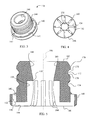
- FIG. 3 depicts a top perspective view of the bumper of the device of FIG. 2 ;
- FIG. 4 depicts a bottom plan view of the bumper of the device of FIG. 2 ;
- FIG. 5 depicts a cross sectional view of the bumper of the device of FIG. 2 showing vents, flutes and grooves formed in the bumper for cooling and controlled deformation of the bumper;
- FIG. 6 depicts a partial simplified side cross sectional view of the drive section of the fastener impacting device of FIG. 1 after the device has been fired and the piston has contacted the microcellular polyurethane elastomer bumper but before deformation of the bumper;
- FIG. 7 depicts a partial simplified side cross sectional view of the drive section of the fastener impacting device of FIG. 1 after the microcellular polyurethane elastomer bumper has been deformed showing a gap remaining between the bumper and the cylinder wall and between the bumper and the drive mechanism.
- FIG. 1 depicts a fastener impacting device 100 including a housing 102 and a fastener cartridge 104.
- the housing 102 defines a handle portion 106, an air receptacle portion 108 and a drive section 110.
- the fastener cartridge 104 in this embodiment is spring biased to force fasteners, such as nails or staples, serially one after the other, into a loaded position adjacent the drive section 110.
- a trigger 112 extends outwardly from the housing 102 and controls the supply of compressed air which is provided from a source of compressed air through an air supply hose 114.
- FIG. 2 is a simplified depiction of the internal components of the drive section 110, a piston 120 is located within a cylinder 122.
- a drive blade 124 is located at one end of the piston 120 and aligned with a drive channel 126 into which a fastener to be driven is forced by the fastener cartridge 104.
- a bumper 128 is positioned at the end portion 130 of the cylinder 122 which opens to the drive channel 126.
- the bumper 128, shown in additional detail in FIGs. 3-5 includes a flange 140, a number of vents 142, and an extension area 144.
- a drive bore 146 extends completely through the bumper 128.
- An inner lip 150 is located between an outer passage 152 and a lower passage 154 in each of the vents 142.
- Each lower passage 154 communicates with an upwardly extending flute 156 within the drive bore 146.
- a portion of the upwardly extending flutes 156 extend in the drive bore 146 along a cylindrical throat 158 which exhibits a uniform diameter.
- an upper conically shaped portion 160 of the drive bore 146 extends outwardly and upwardly to an upper surface 162.
- a lower conically shaped portion 164 of the drive bore 146 extends outwardly and downwardly to a lower surface 166.
- An outer surface 170 of the extension area 144 extends between the upper surface 162 and the flange 140.
- Two grooves 172 and 174 extend radially about the outer surface 170.
- the groove 172 includes opposing walls 176 and 178 which are set at a right angle (90°) to each other.
- the groove 174 is similarly shaped.
- the bumper 128 in this embodiment is constructed using a microcellular polyurethane elastomer (MPE).
- MPEs form a material with numerous randomly oriented air chambers. Some of the air chambers are closed and some are linked. Additionally, the linked air chambers have varying degrees of communication between the chambers and the orientation of the linked chambers varies. Accordingly, when the MPE structure is compressed, air in the chambers is compressed. As the air is compressed, some of the air remains within various chambers, some of the air migrates between other chambers and some of the air is expelled from the structure.
- MPE microcellular polyurethane elastomer
- the manner in which the bumper 128 is deformed when subjected to an impact is a function of the particular geometry of the bumper 128, the cylinder 122, and the piston 120.
- the end portion 130 has a diameter that is closely matched with the diameter of the flange 140. Accordingly, a lip 180, shown in FIG. 2 , which extends about the end portion 130 retains the bumper 128 within the end portion 130 of the cylinder 122.
- the diameter of the extension area 144 has a diameter that is less than the diameter of the cylinder 122 resulting in a gap 182 between the outer surface 170 of the bumper 128 and the cylinder 122.
- the relative diameters of the extension area 144 and the cylinder 122, and thus the size of the gap 182, is selected to reduce or eliminate contact between the extension area 144 and the cylinder 122 as the bumper 128 is compressed. Contact between the extension area 144 and the cylinder 122 can decrease the working life of the bumper 128. Additionally, the radially formed grooves 172 and 174, the shape of the drive bore 146, and the vents 142 guide the manner in which the bumper 128 deforms as described below.
- operation of the fastener impacting device 100 begins with the fastener impacting device in the configuration of FIG. 2 .
- the piston 120 is at the rearward portion of the cylinder 122 and a fastener (not shown) is positioned in the drive channel 126.
- the drive blade 124 is configured to extend into the drive bore 146.
- the drive blade 124 may be spaced apart, but aligned with, the drive bore 146. Additionally, the drive bore 146 and the drive blade 124 are aligned with the drive channel 126.
- the operator manipulates the trigger 112 resulting in venting of compressed air into the cylinder 122 at a location behind the piston 120 (to the right of the piston 120 as viewed in FIG. 2 ).
- the compressed air forces the piston 120 to move in the direction of the arrow 184 of FIG. 2 toward the end portion 130 of the cylinder 122.
- the fastener (not shown) has been driven by the drive blade 124 and the kinetic energy remaining in the piston 120 may be transferred to the bumper 128.
- the piston 120 is in contact with the upper surface 162 of the bumper 128.
- the throat 158 has a diameter that is larger than the base 186 of the drive blade 124.
- the bumper 128 does not contact the drive blade base 186.
- the amount of MPE to be compressed in the bumper 128 has been selected such that when the piston 120 reaches the position shown in FIG. 7 , substantially all of the kinetic energy initially in the piston 120 has been transferred to either the driven fastener or the bumper 128. Additionally, as shown in FIG. 7 , the size of the throat 158 along with the taper of the upper portion 160 and lower portion 164 of the drive bore 146 has guided deformation of the bumper 128 such that the bumper 128 is not in contact with, or is only slightly in contact with, the drive blade 124 and/or the drive blade base 186.
- the piston 120 is returned to the position shown in FIG. 2 . Movement of the piston 120 away from the bumper 128 allows the resilient characteristic of the bumper 128 to reform into the shape shown in FIG .2 . As the bumper 128 reforms, air is provided through the vents 142 to the upwardly extending flutes and the drive bore 146. Air also flows through the outer passages 152 toward the cylinder 122. This air, in addition to refilling air chambers within the bumper 128, removes additional heat from the bumper 128. The remaining air then passes into the area of the cylinder 122 between the bumper 128 and the piston 120.
- a bumper 128 made from MH 24-65 MPE which provides desired kinetic energy transfer and deformation has an overall height of 44 millimeters and includes a flange 140 with a diameter of about 66 millimeters and an extension area 144 with a diameter of 52.6 millimeters.
- the outer passages 152 and the lower passages 154 have diameters of 4 millimeters and the upwardly extending flutes 156 are 4 millimeters wide, about 6.2 millimeters deep, and extend upwardly along the drive bore 140 to a height of 25 millimeters above the lower surface 166.
- the throat 158 has a diameter of 20.1 millimeters and the upper conically shaped portion 160 has a height of 18.1 millimeters and is formed with a cone angle of 20° about a longitudinal axis 190 (see FIG. 5 ).
- the lower conically shaped portion 164 has a height of 13.1 millimeters and is formed with a cone angle of 20° about the longitudinal axis 190.
- the grooves 172 and 174 in this embodiment are about 2 millimeters deep and, at their widest point, are 6.9 millimeters wide.
- the outer surface 170 extends between the grooves 172 and 174 for a distance of 3.2 millimeters. These dimensions may be modified for different applications or design requirements.
- the drive bore may comprise:
- the drive bore may further comprise:
- the device may further comprise:
- the outer wall may define a plurality of grooves extending radially about the MPE bumper.
- Each of the plurality of grooves may extend radially about the entire circumference of the MPE bumper.
- the MPE bumper may further comprise:
- the drive bore may further comprise:
- the throat portion may be is cylindrical.
- the MPE bumper may further comprise:
- the outer wall can be spaced apart from the cylinder wall about the circumference of the cylinder.
Landscapes
- Physics & Mathematics (AREA)
- Fluid Mechanics (AREA)
- Engineering & Computer Science (AREA)
- Mechanical Engineering (AREA)
- Portable Nailing Machines And Staplers (AREA)
Applications Claiming Priority (1)
| Application Number | Priority Date | Filing Date | Title |
|---|---|---|---|
| US12/340,097 US7975777B2 (en) | 2008-12-19 | 2008-12-19 | Cellular foam bumper for nailer |
Publications (2)
| Publication Number | Publication Date |
|---|---|
| EP2199026A1 true EP2199026A1 (de) | 2010-06-23 |
| EP2199026B1 EP2199026B1 (de) | 2017-06-21 |
Family
ID=42106024
Family Applications (1)
| Application Number | Title | Priority Date | Filing Date |
|---|---|---|---|
| EP09179292.9A Not-in-force EP2199026B1 (de) | 2008-12-19 | 2009-12-15 | Dämpfer aus Schaumstoffgefüge für einen Nagler |
Country Status (3)
| Country | Link |
|---|---|
| US (1) | US7975777B2 (de) |
| EP (1) | EP2199026B1 (de) |
| TW (1) | TWI516349B (de) |
Cited By (5)
| Publication number | Priority date | Publication date | Assignee | Title |
|---|---|---|---|---|
| CN102528750A (zh) * | 2010-12-28 | 2012-07-04 | 日立工机株式会社 | 用于调整紧固件的驱动深度的紧固工具 |
| USD677543S1 (en) * | 2011-12-20 | 2013-03-12 | Techtronic Power Tools Technology Limited | Angle finish nailer |
| WO2015073688A1 (en) * | 2013-11-18 | 2015-05-21 | Illinois Tool Works Inc. | Faceted fastener driver bumper with cooling slots |
| USD756740S1 (en) * | 2014-06-02 | 2016-05-24 | Stanley Fastening Systems, L.P. | Pneumatic nailer |
| USD756739S1 (en) * | 2014-06-02 | 2016-05-24 | Stanley Fastening Systems, L.P. | Pneumatic nailer |
Families Citing this family (10)
| Publication number | Priority date | Publication date | Assignee | Title |
|---|---|---|---|---|
| US7870987B1 (en) * | 2009-06-30 | 2011-01-18 | Robert Bosch Gmbh | Fastener driving tool with protection inserts |
| WO2016127101A1 (en) | 2015-02-06 | 2016-08-11 | Milwaukee Electric Tool Corporation | Gas spring-powered fastener driver |
| US20160303728A1 (en) * | 2015-04-17 | 2016-10-20 | Caterpillar Inc. | Hammer Buffer |
| US10654160B2 (en) * | 2017-06-20 | 2020-05-19 | Miner Elastomer Products Corporation | Nail gun recoil bumper |
| WO2023158729A1 (en) | 2022-02-18 | 2023-08-24 | Milwaukee Electric Tool Corporation | Powered fastener driver |
| DE112023000450T5 (de) | 2022-03-04 | 2024-10-24 | Milwaukee Electric Tool Corporation | Fremdkraftbetätigter befestigungsmitteleintreiber |
| US12533778B2 (en) | 2022-03-04 | 2026-01-27 | Milwaukee Electric Tool Corporation | Powered fastener driver |
| US12434367B2 (en) | 2022-03-04 | 2025-10-07 | Milwaukee Electric Tool Corporation | Powered fastener driver |
| DE102024112221A1 (de) | 2023-05-05 | 2024-11-07 | Milwaukee Electric Tool Corporation | Fremdkraftbetätigter befestigungsmitteleintreiber |
| DE102024112566A1 (de) | 2023-05-05 | 2024-11-07 | Milwaukee Electric Tool Corporation | Fremdkraftbetätigter befestigungsmitteleintreiber |
Citations (5)
| Publication number | Priority date | Publication date | Assignee | Title |
|---|---|---|---|---|
| GB1132954A (en) * | 1966-04-07 | 1968-11-06 | Angus George Co Ltd | Improvements in and relating to anti-vibration mounting elements |
| US3496840A (en) * | 1968-01-29 | 1970-02-24 | Fastener Corp | Fastener driving apparatus |
| US4509669A (en) * | 1981-05-20 | 1985-04-09 | Joh. Friedrich Behrens Ag | Sound-dampened driving apparatus for fasteners |
| US4932480A (en) * | 1988-12-16 | 1990-06-12 | Illinois Tool Works Inc. | Driving tool with air-cooled bumper |
| WO2007142997A2 (en) * | 2006-05-31 | 2007-12-13 | Stanley Fastening Systems, L.P. | Fastener driving device |
Family Cites Families (20)
| Publication number | Priority date | Publication date | Assignee | Title |
|---|---|---|---|---|
| US3104395A (en) * | 1957-11-22 | 1963-09-24 | Jr Hugh M Grey | Automatic nailer |
| US3661216A (en) * | 1969-09-10 | 1972-05-09 | Nippon Pneumatic Mfg | Impact air driven tool |
| DE2339163C2 (de) * | 1973-08-02 | 1975-01-30 | Karl M. Reich, Maschinenfabrik Gmbh, 7440 Nuertingen | Schlagpuffer für Einschlaggeräte |
| US4188858A (en) * | 1978-05-11 | 1980-02-19 | Signode Corporation | Bumper deterioration warning system for fastener driving tools |
| US4401251A (en) * | 1980-11-19 | 1983-08-30 | Signode Corporation | Bumperless gun nailer |
| US4549344A (en) * | 1980-11-19 | 1985-10-29 | Signode Corporation | Method of driving fasteners with a bumperless pneumatic gun |
| DE3047662C2 (de) * | 1980-12-18 | 1985-02-21 | Karl M. Reich Maschinenfabrik GmbH, 7440 Nürtingen | Puffersystem bei Einschlaggeräten |
| US5131579A (en) * | 1988-03-02 | 1992-07-21 | Max Co., Ltd. | Nailing machine |
| DE3924620A1 (de) * | 1989-07-26 | 1991-01-31 | Hilti Ag | Pulverkraftbetriebenes bolzensetzgeraet |
| GB2265106B (en) * | 1992-03-18 | 1995-07-05 | Max Co Ltd | Air-pressure-operated impulsion mechanism |
| JPH07156078A (ja) * | 1993-12-03 | 1995-06-20 | Kanematsu Nnk Corp | 固着具打撃工具 |
| JP3626011B2 (ja) * | 1998-05-11 | 2005-03-02 | 株式会社マキタ | 釘打ち機 |
| JP3622193B2 (ja) * | 1999-03-04 | 2005-02-23 | マックス株式会社 | 釘打機、タッカ等のバンパ |
| US6619527B1 (en) * | 2000-10-10 | 2003-09-16 | Illinois Tool Works Inc. | Combustion powered tool suspension for iron core fan motor |
| US6648202B2 (en) * | 2001-02-08 | 2003-11-18 | Black & Decker Inc. | Pneumatic fastening tool |
| US6779698B2 (en) * | 2001-10-15 | 2004-08-24 | Hwai-Tay Lin | Abrasion-resistant bumper for a nail-driving tool |
| JP3818234B2 (ja) * | 2002-07-19 | 2006-09-06 | 日立工機株式会社 | 釘打機 |
| US6695192B1 (en) * | 2002-09-30 | 2004-02-24 | Illinois Tool Works Inc. | Adjustable depth control for fastener driving tool |
| TW200600288A (en) * | 2004-02-20 | 2006-01-01 | Black & Decker Inc | Adjustable exhaust system for pneumatic nailers and staplers |
| US7905377B2 (en) * | 2008-08-14 | 2011-03-15 | Robert Bosch Gmbh | Flywheel driven nailer with safety mechanism |
-
2008
- 2008-12-19 US US12/340,097 patent/US7975777B2/en not_active Expired - Fee Related
-
2009
- 2009-12-11 TW TW098142393A patent/TWI516349B/zh not_active IP Right Cessation
- 2009-12-15 EP EP09179292.9A patent/EP2199026B1/de not_active Not-in-force
Patent Citations (5)
| Publication number | Priority date | Publication date | Assignee | Title |
|---|---|---|---|---|
| GB1132954A (en) * | 1966-04-07 | 1968-11-06 | Angus George Co Ltd | Improvements in and relating to anti-vibration mounting elements |
| US3496840A (en) * | 1968-01-29 | 1970-02-24 | Fastener Corp | Fastener driving apparatus |
| US4509669A (en) * | 1981-05-20 | 1985-04-09 | Joh. Friedrich Behrens Ag | Sound-dampened driving apparatus for fasteners |
| US4932480A (en) * | 1988-12-16 | 1990-06-12 | Illinois Tool Works Inc. | Driving tool with air-cooled bumper |
| WO2007142997A2 (en) * | 2006-05-31 | 2007-12-13 | Stanley Fastening Systems, L.P. | Fastener driving device |
Cited By (7)
| Publication number | Priority date | Publication date | Assignee | Title |
|---|---|---|---|---|
| CN102528750A (zh) * | 2010-12-28 | 2012-07-04 | 日立工机株式会社 | 用于调整紧固件的驱动深度的紧固工具 |
| USD677543S1 (en) * | 2011-12-20 | 2013-03-12 | Techtronic Power Tools Technology Limited | Angle finish nailer |
| WO2015073688A1 (en) * | 2013-11-18 | 2015-05-21 | Illinois Tool Works Inc. | Faceted fastener driver bumper with cooling slots |
| US9664045B2 (en) | 2013-11-18 | 2017-05-30 | Illinois Tool Works Inc. | Faceted fastener driver bumper with cooling slots |
| US10711610B2 (en) | 2013-11-18 | 2020-07-14 | Illinois Tool Works Inc. | Faceted fastener driver bumper with cooling slots |
| USD756740S1 (en) * | 2014-06-02 | 2016-05-24 | Stanley Fastening Systems, L.P. | Pneumatic nailer |
| USD756739S1 (en) * | 2014-06-02 | 2016-05-24 | Stanley Fastening Systems, L.P. | Pneumatic nailer |
Also Published As
| Publication number | Publication date |
|---|---|
| TW201032977A (en) | 2010-09-16 |
| TWI516349B (zh) | 2016-01-11 |
| US20100155097A1 (en) | 2010-06-24 |
| EP2199026B1 (de) | 2017-06-21 |
| US7975777B2 (en) | 2011-07-12 |
Similar Documents
| Publication | Publication Date | Title |
|---|---|---|
| US7975777B2 (en) | Cellular foam bumper for nailer | |
| US6779699B2 (en) | Pneumatically operated nail gun having cylinder floating prevention arrangement | |
| EP2533944B1 (de) | Druckluftnagler mit muffenbetriebenem kolbenrückschlag | |
| US3969989A (en) | Impact buffer for impact drive tools | |
| TWI549788B (zh) | 打擊工具及打擊工具用緩衝器 | |
| EP2103387A1 (de) | Elektrowerkzeug und dämpfungsmechanismus dafür | |
| TWI399270B (zh) | 扣件驅動工具 | |
| JP5716395B2 (ja) | 打込機 | |
| CN109093567B (zh) | 钉枪反冲缓冲器 | |
| EP2221148B1 (de) | Hammerplatte für ein Nagelsetzgerät | |
| AU2005201108B2 (en) | Fastener driving tool and magazine device | |
| JP3622193B2 (ja) | 釘打機、タッカ等のバンパ | |
| JP4687572B2 (ja) | 打込機 | |
| KR101212197B1 (ko) | 연소 동력식 파스너-박는 공구를 위한 보조 연소 챔버를 구비한 구동기 블레이드 | |
| US6981474B2 (en) | Setting tool | |
| JP4569521B2 (ja) | 打込機 | |
| TWM618193U (zh) | 避震式往復氣動工具 | |
| JP4174727B2 (ja) | 釘打機 | |
| JP2010228010A (ja) | 打込機 | |
| KR100502682B1 (ko) | 범퍼 열화방지 및 챔버내 저항 감소를 위해 이중공기유통홈이 형성된 타카장치 | |
| WO2023080192A1 (ja) | 作業機 | |
| SE545906C2 (en) | Hand-held percussive tool | |
| HK1260032A1 (en) | Nail gun recoil bumper | |
| JP5845492B2 (ja) | 作業工具 | |
| JP2019107723A (ja) | 打込み機 |
Legal Events
| Date | Code | Title | Description |
|---|---|---|---|
| PUAI | Public reference made under article 153(3) epc to a published international application that has entered the european phase |
Free format text: ORIGINAL CODE: 0009012 |
|
| AK | Designated contracting states |
Kind code of ref document: A1 Designated state(s): AT BE BG CH CY CZ DE DK EE ES FI FR GB GR HR HU IE IS IT LI LT LU LV MC MK MT NL NO PL PT RO SE SI SK SM TR |
|
| AX | Request for extension of the european patent |
Extension state: AL BA RS |
|
| RTI1 | Title (correction) |
Free format text: CELLULAR FOAM BUMPER FOR NAILER |
|
| 17P | Request for examination filed |
Effective date: 20101223 |
|
| GRAP | Despatch of communication of intention to grant a patent |
Free format text: ORIGINAL CODE: EPIDOSNIGR1 |
|
| STAA | Information on the status of an ep patent application or granted ep patent |
Free format text: STATUS: GRANT OF PATENT IS INTENDED |
|
| INTG | Intention to grant announced |
Effective date: 20170105 |
|
| GRAS | Grant fee paid |
Free format text: ORIGINAL CODE: EPIDOSNIGR3 |
|
| GRAA | (expected) grant |
Free format text: ORIGINAL CODE: 0009210 |
|
| STAA | Information on the status of an ep patent application or granted ep patent |
Free format text: STATUS: THE PATENT HAS BEEN GRANTED |
|
| AK | Designated contracting states |
Kind code of ref document: B1 Designated state(s): AT BE BG CH CY CZ DE DK EE ES FI FR GB GR HR HU IE IS IT LI LT LU LV MC MK MT NL NO PL PT RO SE SI SK SM TR |
|
| REG | Reference to a national code |
Ref country code: GB Ref legal event code: FG4D |
|
| REG | Reference to a national code |
Ref country code: CH Ref legal event code: EP |
|
| REG | Reference to a national code |
Ref country code: IE Ref legal event code: FG4D |
|
| REG | Reference to a national code |
Ref country code: AT Ref legal event code: REF Ref document number: 902488 Country of ref document: AT Kind code of ref document: T Effective date: 20170715 |
|
| REG | Reference to a national code |
Ref country code: DE Ref legal event code: R096 Ref document number: 602009046703 Country of ref document: DE |
|
| REG | Reference to a national code |
Ref country code: NL Ref legal event code: MP Effective date: 20170621 |
|
| PG25 | Lapsed in a contracting state [announced via postgrant information from national office to epo] |
Ref country code: FI Free format text: LAPSE BECAUSE OF FAILURE TO SUBMIT A TRANSLATION OF THE DESCRIPTION OR TO PAY THE FEE WITHIN THE PRESCRIBED TIME-LIMIT Effective date: 20170621 Ref country code: HR Free format text: LAPSE BECAUSE OF FAILURE TO SUBMIT A TRANSLATION OF THE DESCRIPTION OR TO PAY THE FEE WITHIN THE PRESCRIBED TIME-LIMIT Effective date: 20170621 Ref country code: GR Free format text: LAPSE BECAUSE OF FAILURE TO SUBMIT A TRANSLATION OF THE DESCRIPTION OR TO PAY THE FEE WITHIN THE PRESCRIBED TIME-LIMIT Effective date: 20170922 Ref country code: NO Free format text: LAPSE BECAUSE OF FAILURE TO SUBMIT A TRANSLATION OF THE DESCRIPTION OR TO PAY THE FEE WITHIN THE PRESCRIBED TIME-LIMIT Effective date: 20170921 Ref country code: LT Free format text: LAPSE BECAUSE OF FAILURE TO SUBMIT A TRANSLATION OF THE DESCRIPTION OR TO PAY THE FEE WITHIN THE PRESCRIBED TIME-LIMIT Effective date: 20170621 |
|
| REG | Reference to a national code |
Ref country code: LT Ref legal event code: MG4D |
|
| REG | Reference to a national code |
Ref country code: AT Ref legal event code: MK05 Ref document number: 902488 Country of ref document: AT Kind code of ref document: T Effective date: 20170621 |
|
| PG25 | Lapsed in a contracting state [announced via postgrant information from national office to epo] |
Ref country code: LV Free format text: LAPSE BECAUSE OF FAILURE TO SUBMIT A TRANSLATION OF THE DESCRIPTION OR TO PAY THE FEE WITHIN THE PRESCRIBED TIME-LIMIT Effective date: 20170621 Ref country code: SE Free format text: LAPSE BECAUSE OF FAILURE TO SUBMIT A TRANSLATION OF THE DESCRIPTION OR TO PAY THE FEE WITHIN THE PRESCRIBED TIME-LIMIT Effective date: 20170621 Ref country code: NL Free format text: LAPSE BECAUSE OF FAILURE TO SUBMIT A TRANSLATION OF THE DESCRIPTION OR TO PAY THE FEE WITHIN THE PRESCRIBED TIME-LIMIT Effective date: 20170621 Ref country code: BG Free format text: LAPSE BECAUSE OF FAILURE TO SUBMIT A TRANSLATION OF THE DESCRIPTION OR TO PAY THE FEE WITHIN THE PRESCRIBED TIME-LIMIT Effective date: 20170921 |
|
| PG25 | Lapsed in a contracting state [announced via postgrant information from national office to epo] |
Ref country code: CZ Free format text: LAPSE BECAUSE OF FAILURE TO SUBMIT A TRANSLATION OF THE DESCRIPTION OR TO PAY THE FEE WITHIN THE PRESCRIBED TIME-LIMIT Effective date: 20170621 Ref country code: EE Free format text: LAPSE BECAUSE OF FAILURE TO SUBMIT A TRANSLATION OF THE DESCRIPTION OR TO PAY THE FEE WITHIN THE PRESCRIBED TIME-LIMIT Effective date: 20170621 Ref country code: AT Free format text: LAPSE BECAUSE OF FAILURE TO SUBMIT A TRANSLATION OF THE DESCRIPTION OR TO PAY THE FEE WITHIN THE PRESCRIBED TIME-LIMIT Effective date: 20170621 Ref country code: RO Free format text: LAPSE BECAUSE OF FAILURE TO SUBMIT A TRANSLATION OF THE DESCRIPTION OR TO PAY THE FEE WITHIN THE PRESCRIBED TIME-LIMIT Effective date: 20170621 Ref country code: SK Free format text: LAPSE BECAUSE OF FAILURE TO SUBMIT A TRANSLATION OF THE DESCRIPTION OR TO PAY THE FEE WITHIN THE PRESCRIBED TIME-LIMIT Effective date: 20170621 |
|
| PG25 | Lapsed in a contracting state [announced via postgrant information from national office to epo] |
Ref country code: IS Free format text: LAPSE BECAUSE OF FAILURE TO SUBMIT A TRANSLATION OF THE DESCRIPTION OR TO PAY THE FEE WITHIN THE PRESCRIBED TIME-LIMIT Effective date: 20171021 Ref country code: SM Free format text: LAPSE BECAUSE OF FAILURE TO SUBMIT A TRANSLATION OF THE DESCRIPTION OR TO PAY THE FEE WITHIN THE PRESCRIBED TIME-LIMIT Effective date: 20170621 Ref country code: IT Free format text: LAPSE BECAUSE OF FAILURE TO SUBMIT A TRANSLATION OF THE DESCRIPTION OR TO PAY THE FEE WITHIN THE PRESCRIBED TIME-LIMIT Effective date: 20170621 Ref country code: PL Free format text: LAPSE BECAUSE OF FAILURE TO SUBMIT A TRANSLATION OF THE DESCRIPTION OR TO PAY THE FEE WITHIN THE PRESCRIBED TIME-LIMIT Effective date: 20170621 Ref country code: ES Free format text: LAPSE BECAUSE OF FAILURE TO SUBMIT A TRANSLATION OF THE DESCRIPTION OR TO PAY THE FEE WITHIN THE PRESCRIBED TIME-LIMIT Effective date: 20170621 |
|
| REG | Reference to a national code |
Ref country code: DE Ref legal event code: R097 Ref document number: 602009046703 Country of ref document: DE |
|
| PLBE | No opposition filed within time limit |
Free format text: ORIGINAL CODE: 0009261 |
|
| STAA | Information on the status of an ep patent application or granted ep patent |
Free format text: STATUS: NO OPPOSITION FILED WITHIN TIME LIMIT |
|
| PG25 | Lapsed in a contracting state [announced via postgrant information from national office to epo] |
Ref country code: DK Free format text: LAPSE BECAUSE OF FAILURE TO SUBMIT A TRANSLATION OF THE DESCRIPTION OR TO PAY THE FEE WITHIN THE PRESCRIBED TIME-LIMIT Effective date: 20170621 |
|
| PGFP | Annual fee paid to national office [announced via postgrant information from national office to epo] |
Ref country code: DE Payment date: 20171229 Year of fee payment: 9 |
|
| 26N | No opposition filed |
Effective date: 20180322 |
|
| REG | Reference to a national code |
Ref country code: CH Ref legal event code: PL |
|
| GBPC | Gb: european patent ceased through non-payment of renewal fee |
Effective date: 20171215 |
|
| PG25 | Lapsed in a contracting state [announced via postgrant information from national office to epo] |
Ref country code: SI Free format text: LAPSE BECAUSE OF FAILURE TO SUBMIT A TRANSLATION OF THE DESCRIPTION OR TO PAY THE FEE WITHIN THE PRESCRIBED TIME-LIMIT Effective date: 20170621 |
|
| REG | Reference to a national code |
Ref country code: IE Ref legal event code: MM4A |
|
| PG25 | Lapsed in a contracting state [announced via postgrant information from national office to epo] |
Ref country code: MT Free format text: LAPSE BECAUSE OF NON-PAYMENT OF DUE FEES Effective date: 20171215 Ref country code: LU Free format text: LAPSE BECAUSE OF NON-PAYMENT OF DUE FEES Effective date: 20171215 |
|
| REG | Reference to a national code |
Ref country code: FR Ref legal event code: ST Effective date: 20180831 |
|
| REG | Reference to a national code |
Ref country code: BE Ref legal event code: MM Effective date: 20171231 |
|
| PG25 | Lapsed in a contracting state [announced via postgrant information from national office to epo] |
Ref country code: FR Free format text: LAPSE BECAUSE OF NON-PAYMENT OF DUE FEES Effective date: 20180102 Ref country code: IE Free format text: LAPSE BECAUSE OF NON-PAYMENT OF DUE FEES Effective date: 20171215 |
|
| PG25 | Lapsed in a contracting state [announced via postgrant information from national office to epo] |
Ref country code: BE Free format text: LAPSE BECAUSE OF NON-PAYMENT OF DUE FEES Effective date: 20171231 Ref country code: LI Free format text: LAPSE BECAUSE OF NON-PAYMENT OF DUE FEES Effective date: 20171231 Ref country code: GB Free format text: LAPSE BECAUSE OF NON-PAYMENT OF DUE FEES Effective date: 20171215 Ref country code: CH Free format text: LAPSE BECAUSE OF NON-PAYMENT OF DUE FEES Effective date: 20171231 |
|
| PG25 | Lapsed in a contracting state [announced via postgrant information from national office to epo] |
Ref country code: HU Free format text: LAPSE BECAUSE OF FAILURE TO SUBMIT A TRANSLATION OF THE DESCRIPTION OR TO PAY THE FEE WITHIN THE PRESCRIBED TIME-LIMIT; INVALID AB INITIO Effective date: 20091215 Ref country code: MC Free format text: LAPSE BECAUSE OF FAILURE TO SUBMIT A TRANSLATION OF THE DESCRIPTION OR TO PAY THE FEE WITHIN THE PRESCRIBED TIME-LIMIT Effective date: 20170621 |
|
| REG | Reference to a national code |
Ref country code: DE Ref legal event code: R119 Ref document number: 602009046703 Country of ref document: DE |
|
| PG25 | Lapsed in a contracting state [announced via postgrant information from national office to epo] |
Ref country code: DE Free format text: LAPSE BECAUSE OF NON-PAYMENT OF DUE FEES Effective date: 20190702 Ref country code: CY Free format text: LAPSE BECAUSE OF NON-PAYMENT OF DUE FEES Effective date: 20170621 |
|
| PG25 | Lapsed in a contracting state [announced via postgrant information from national office to epo] |
Ref country code: MK Free format text: LAPSE BECAUSE OF FAILURE TO SUBMIT A TRANSLATION OF THE DESCRIPTION OR TO PAY THE FEE WITHIN THE PRESCRIBED TIME-LIMIT Effective date: 20170621 |
|
| PG25 | Lapsed in a contracting state [announced via postgrant information from national office to epo] |
Ref country code: TR Free format text: LAPSE BECAUSE OF FAILURE TO SUBMIT A TRANSLATION OF THE DESCRIPTION OR TO PAY THE FEE WITHIN THE PRESCRIBED TIME-LIMIT Effective date: 20170621 |
|
| PG25 | Lapsed in a contracting state [announced via postgrant information from national office to epo] |
Ref country code: PT Free format text: LAPSE BECAUSE OF FAILURE TO SUBMIT A TRANSLATION OF THE DESCRIPTION OR TO PAY THE FEE WITHIN THE PRESCRIBED TIME-LIMIT Effective date: 20170621 |