EP2199172B1 - Seilbahnkabine und Seilbahnanlage wobei die Kabine auf jeder Längsseite mit einer Tür versehen ist - Google Patents
Seilbahnkabine und Seilbahnanlage wobei die Kabine auf jeder Längsseite mit einer Tür versehen ist Download PDFInfo
- Publication number
- EP2199172B1 EP2199172B1 EP09450123A EP09450123A EP2199172B1 EP 2199172 B1 EP2199172 B1 EP 2199172B1 EP 09450123 A EP09450123 A EP 09450123A EP 09450123 A EP09450123 A EP 09450123A EP 2199172 B1 EP2199172 B1 EP 2199172B1
- Authority
- EP
- European Patent Office
- Prior art keywords
- cabins
- cable car
- cabin
- aerial cableway
- end stations
- Prior art date
- Legal status (The legal status is an assumption and is not a legal conclusion. Google has not performed a legal analysis and makes no representation as to the accuracy of the status listed.)
- Not-in-force
Links
Images
Classifications
-
- B—PERFORMING OPERATIONS; TRANSPORTING
- B61—RAILWAYS
- B61B—RAILWAY SYSTEMS; EQUIPMENT THEREFOR NOT OTHERWISE PROVIDED FOR
- B61B12/00—Component parts, details or accessories not provided for in groups B61B7/00 - B61B11/00
- B61B12/002—Cabins; Ski-lift seats
-
- B—PERFORMING OPERATIONS; TRANSPORTING
- B61—RAILWAYS
- B61B—RAILWAY SYSTEMS; EQUIPMENT THEREFOR NOT OTHERWISE PROVIDED FOR
- B61B1/00—General arrangement of stations, platforms, or sidings; Railway networks; Rail vehicle marshalling systems
- B61B1/02—General arrangement of stations and platforms including protection devices for the passengers
-
- B—PERFORMING OPERATIONS; TRANSPORTING
- B61—RAILWAYS
- B61B—RAILWAY SYSTEMS; EQUIPMENT THEREFOR NOT OTHERWISE PROVIDED FOR
- B61B12/00—Component parts, details or accessories not provided for in groups B61B7/00 - B61B11/00
- B61B12/02—Suspension of the load; Guiding means, e.g. wheels; Attaching traction cables
- B61B12/022—Vehicle receiving and dispatching devices
- B61B12/024—Docking devices
Definitions
- the subject invention relates to a cable car system with at least one support or hoisting rope, which is guided in the two end stations of the cable car over deflection pulleys, of which at least one is driven, and with cable car cabins, which are coupled to the support and hoisting rope, where they uncoupled in the end stations of the support or hoisting rope, along guide rails moved through the end stations and are subsequently coupled to the support and hoisting rope, wherein further the cable car cabins are formed at their two longitudinal side walls, each with at least one door, and in the End stations along both sides of at least one trajectory of the cable car cabins Perrone for boarding or leaving the cable car cabins are provided by the passengers.
- a cable car system with cable car cabins in which the cable car cabins are formed at their two longitudinal side walls with doors and in which a middle platform is provided in the end stations, around which the cable car cabins are guided around and on the outside of the running around the middle platform curved trajectory the cable car cabins each a further platform is provided.
- this cable car so passengers can simultaneously get out of the cable car cabins on the middle platform and on one of the two side Perrone or get into the cable car cabins from the middle platform and the two side perron.
- the present invention is based on the object, a cable car system in which the cable car cabins are moved through the two end stations in circulation to create, through which avoided the existing in such cable car installations disadvantages of low production capacity and large footprint become.
- This is inventively achieved in that at least one pair of turnouts is provided in at least one of the end stations in the trajectory of the cable car cabins, connect to which further guide rails, whereby two adjacent paths of movement are created, and that the cable car cabins along two in the end station side by side located guide rails along the two juxtaposed movement paths are moved, which two trajectories are assigned only three perforations, of which the middle platform is associated with both trajectories, wherein the middle platform (6b) is located between the two Bewegunsbahnen.
- a first of these is intended for those passengers boarding the cable car cabins
- the second of these is intended for those passengers leaving the cable car cabins.
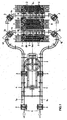
- FIG.1 and FIG.2 one of the end stations of a cable car system according to the invention is shown.
- This cableway system has a carrying and conveying cable 1, which is moved, for example, at a speed of 6 m / sec, wherein it is guided in one of the end stations via a deflecting plate 2.
- Cable car cabins 3 are coupled to this support and hoisting rope 1, which in the end station is uncoupled from the strand 1a of the support and hoisting rope 1 moving in it along a guide rail 4 through this end station and subsequently to the latter
- This station also moving strand 1b of the support and hoisting rope 1 are coupled.
- delay wheels 5a, 5b and 5c acceleration wheels 5c provided, by means of which the speed of the uncoupled from Seiltrum 1a cable car cabins 3 is reduced to a speed of, for example, 0.3 m / sec, with which speed through an entry and exit area 6 are moved through for the passengers. Then the cable car cabins 3 are accelerated again to the speed of movement of the carrying and conveying cable 3, whereupon they are coupled to the strand leaving the station 1b of the carrying and conveying cable 1.
- the cable car cabins 3 are formed at their two longitudinal side walls with at least one door 31 and 32. Furthermore, the guide rail 4 is formed with a pair of switches 41 and 42, to which two side by side guide rails 4a and 4b, along which the cable car cabins 3 are moved along two adjacent movement paths through the entry and exit area 6 therethrough. These two trajectories are associated with three perforations 6a, 6b and 6c, the perforations 6a and 6b of the first trajectory of the cable car cabins 3 and the perforations 6b and 6c of the second trajectory of the cable car cabins 3 are assigned. The middle platform 6b is associated with both trajectories. A first platform may be intended for the passengers leaving the cable car cabins 3, and a second platform may be intended for the passengers boarding the cable car cabins 3.
- This design of the cable car system makes it easier for the passengers to climb and exit the cable car cabins 3, since with the same conveying capacity of the cable car cabins 3, only half the number of passengers moves through each of the two doors 31 and 32 of the cable car cabins 3.
- a plurality of pairs of switches 41 and 42 may be provided, whereby more than two adjacent paths of movement are created, each associated with two perforators for boarding the cable car cabins or for leaving the cable car cabins.
Landscapes
- Engineering & Computer Science (AREA)
- Transportation (AREA)
- Mechanical Engineering (AREA)
- Lift-Guide Devices, And Elevator Ropes And Cables (AREA)
- Body Structure For Vehicles (AREA)
- Intermediate Stations On Conveyors (AREA)
- Platform Screen Doors And Railroad Systems (AREA)
Description
- Die gegenständliche Erfindung betrifft eine Seilbahnanlage mit mindestens einem Trag- bzw. Förderseil, welches in den beiden Endstationen der Seilbahnanlage über Umlenkscheiben geführt ist, von welchen mindestens eine angetrieben ist, und mit Seilbahnkabinen, welche mit dem Trag- und Förderseil kuppelbar sind, wobei sie in den Endstationen vom Trag- bzw. Förderseil abgekuppelt, längs Führungsschienen durch die Endstationen hindurch bewegt sowie in der Folge an das Trag- und Förderseil angekuppelt werden, wobei weiters die Seilbahnkabinen an ihren beiden Längsseitenwänden mit jeweils mindestens einer Türe ausgebildet sind, sowie in den Endstationen längs beider Seiten der mindestens einen Bewegungsbahn der Seilbahnkabinen Perrone für das Besteigen bzw. das Verlassen der Seilbahnkabinen durch die Passagiere vorgesehen sind.
- Bei Seilbahnanlagen, bei welchen das Trag- bzw. Förderseil in den Endstationen über Umlenkscheiben, von welchen mindestens eine angetrieben ist, geführt werden und weiters mit Seilbahnkabinen, welche mit dem Trag- und Förderseil kuppelbar sind, wobei sie in den Endstationen vom Trag- bzw. Förderseil abgekuppelt, längs Führungsschienen durch die Endstationen hindurch bewegt und in der Folge an das Trag- und Förderseil angekuppelt werden, also bei solchen Seilbahnanlagen, bei welchen die Seilbahnkabinen durch die Endstationen im Umlauf hindurchgeführt werden, befinden sich in den Endstationen jeweils an einer Seite der Bewegungsbahn Perrone, von welchen aus die Passagiere die Seilbahnkabinen besteigen bzw. auf welche diejenigen Passagiere, welche die Seilbahnkabinen verlassen, gelangen. Es ist dabei bekannt, die Seilbahnkabinen jeweils auf einer ihrer beiden Längssseitenwände mit Türen auszubilden, durch welche hindurch die Passagiere die Seilbahnkabinen verlassen oder in diese hinein gelangen.
- Wenngleich bei diesen bekannten Seilbahnanlagen die Seilbahnkabinen in den Endstationen vom Trag- bzw. Förderseil abgekuppelt werden und die Seilbahnkabinen durch die Endstationen mit einer nur geringen Geschwindigkeit hindurch bewegt werden, bedingt es für die Passagiere eine Belastung, zugleich mit anderen Personen aus einer sich bewegenden Seilbahn kabine auszusteigen oder in diese einzusteigen, insbesondere dann, wenn gleichzeitig gegenläufige Bewegungen der Passagiere, also ein Aussteigen und ein Einsteigen von Passagieren, erfolgen.
- Um diese Nachteile zu vermeiden, ist es bekannt, in Stationen von Seilbahnanlagen einerseits Bereiche von Perronen vorzusehen, welche für aus den Seilbahnkabinen aussteigende Passagiere -bestimmt sind und in Bewegungsrichtung der Seilbahnkabinen dahinter befindliche Bereiche von Perronen vorzusehen, welche für diejenigen Passagiere bestimmt sind, welche in die Seilbahnkabinen einsteigen. Allerdings bedingt eine derartige Unterteilung der Perrone sich in Bewegungsrichtung der Seilbahnkabinen erstreckende Perrone mit einem Platzbedarf, welcher bei vorgegebenen räumlichen Gegebenheiten oftmals nicht zur Verfügung steht.
- Es ist weiters bekannt, bei Pendelbahnen, also bei solchen Seilbahnanlagen, bei welchen zwei Tragseile vorgesehen sind, längs welcher mittels diesen zugeordneter Förderseile jeweils eine Seilbahnkabine längs zweier paralleler Bahnen hin- und herbewegt werden, mehrere Perrone vorzusehen, welche den beiden Bewegungsbahnen zugeordnet sind, und weiters die Seilbahnkabinen an ihren beiden Längsseitenwänden mit Türen auszubilden. Allerdings weisen derartige Pendelbahnen deshalb, da sie nur zwei Seilbahnkabinen aufweisen, gegenüber solcher Seilbahnanlagen, bei welchen die Seilbahnkabinen durch die Endstationen hindurch im Umlauf bewegt werden und bei welchen eine Vielzahl von Seilbahnkabinen vorgesehen ist, eine weitaus geringere Förderkapazität auf.
- Aus der
FR-2731196-A1 - Aus der
JP 3132465 A - Diese bekannte Seilbahnanlage entspricht jedoch deshalb nicht den technischen Erfordernissen, da an den Perronen nur eine einzige Bewegungsbahn vorbeiführt, wodurch die Förderkapazität dieser Seilbahnanlage beschränkt ist.
- Der gegenständlichen Erfindung liegt die Aufgabe zugrunde, eine Seilbahnanlage, bei welcher die Seilbahnkabinen durch die beiden Endstationen im Umlauf hindurch bewegt werden, zu schaffen, durch welche die bisher bei derartigen Seilbahnanlagen bestehenden Nachteile der geringen Förderkapazität bzw. des großen Platzbedarfes vermieden werden. Dies wird erfindungsgemäß dadurch erzielt, dass in mindestens einer der Endstationen in der Bewegungsbahn der Seilbahnkabinen mindestens ein Paar von Weichen vorgesehen ist, an welche weitere Führungsschienen anschließen, wodurch zwei nebeneinander verlaufende Bewegungsbahnen geschaffen sind, und dass die Seilbahnkabinen längs zweier sich in der Endstation nebeneinander befindlichen Führungsschienen längs den beiden nebeneinander verlaufenden Bewegungsbahnen bewegt werden, welchen beiden Bewegungsbahnen nur drei Perrone zugeordnet sind, von welchen der mittlere Perron beiden Bewegungsbahnen zugeordnet ist, wobei sich der mittlere Perron (6b) zwischen den beiden Bewegunsbahnen befindet. Vorzugsweise ist von den zwei einer Bewegungsbahn zugeordneten Perronen ein erster derselben für diejenigen Passagiere bestimmt, welche die Seilbahnkabinen besteigen, und der zweite derselben für diejenigen Passagiere bestimmt, welche die Seilbahnkabinen verlassen.
- Der Gegenstand der Erfindung ist nachstehend anhand eines in der Zeichnung dargestellten Ausführungsbeispieles näher erläutert. Es zeigen:
- FIG.1
- eine der Endstationen einer erfindungsgemäßen Seilbahnanlage, in Draufsicht, und
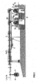
- FIG.2
- die Endstation gemäß
FIG.1 , in Seitenansicht. - In den
FIG.1 undFIG.2 ist eine der Endstationen einer erfindungsgemäßen Seilbahnanlage dargestellt. Diese Seilbahnanlage weist ein Trag- und Förderseil 1 auf, welches z.B. mit einer Geschwindigkeit von 6 m/sec bewegt wird, wobei es in einer der Endstationen über eine Umlenkscheibe 2 geführt ist. An dieses Trag- und Förderseil 1 sind Seilbahnkabinen 3 angekuppelt, welche in der Endstation von dem sich in diese hinein bewegenden Trum 1a des Trag- und Förderseiles 1 abgekuppelt, längs einer Führungsschiene 4 durch diese Endstation hindurch geführt und in der Folge an das sich aus dieser Station hinaus bewegende Trum 1b des Trag- und Förderseiles 1 angekuppelt werden. Längs der Führungsschienen 4 sind Verzögerungsräder 5a, Förderräder 5b und Beschleunigungsräder 5c vorgesehen, mittels welcher die Geschwindigkeit der vom Seiltrum 1a abgekuppelten Seilbahnkabinen 3 auf eine Geschwindigkeit von z.B. 0,3 m/ sec vermindert wird, mit welcher Geschwindigkeit sie durch einen Ein- und Ausstiegsbereich 6 für die Passagiere hindurch bewegt werden. Hierauf werden die Seilbahnkabinen 3 wieder auf die Bewegungsgeschwindigkeit des Trag- und Förderseiles 3 beschleunigt, worauf sie an das die Station verlassende Trum 1b des Trag- und Förderseiles 1 angekuppelt werden. - Die Seilbahnkabinen 3 sind an ihren beiden Längsseitenwänden mit mindestens einer Türe 31 und 32 ausgebildet. Weiters ist die Führungsschiene 4 mit einem Paar von Weichen 41 und 42 ausgebildet, an welche zwei nebeneinander befindliche Führungsschienen 4a und 4b anschließen, längs welcher die Seilbahnkabinen 3 längs zweier nebeneinander liegender Bewegungsbahnen durch den Ein- und Ausstiegsbereich 6 hindurch bewegt werden. Diesen beiden Bewegungsbahnen sind drei Perrone 6a, 6b und 6c zugeordnet, wobei die Perrone 6a und 6b der ersten Bewegungsbahne der Seilbahnkabinen 3 und die Perrone 6b und 6c der zweiten Bewegungsbahn der Seilbahnkabinen 3 zugeordnet sind. Der mittlere Perron 6b ist beiden Bewegungsbahnen zugeordnet. Ein erster Perron kann für die die Seilbahnkabinen 3 verlassenden Passagiere und ein zweiter Perron kann für die die Seilbahnkabinen 3 besteigenden Passagiere bestimmt sein.
- Durch diese Ausbildung der Seilbahnanlage wird für die Passagiere eine Erleichterung beim Besteigen und beim Verlassen der Seilbahnkabinen 3 erzielt, da bei gleicher Förderkapazität der Seilbahnkabinen 3 sich durch jede der beiden Türen 31 und 32 der Seilbahnkabinen 3 nur die halbe Anzahl von Passagieren hindurch bewegt.
- In Bezug auf den bekannten Stand der Technik, gemäß welchem für die die Seilbahnkabinen 3 verlassenden Passagiere einerseits und für die in die Seilbahnkabinen 3 einsteigenden Passagiere andererseits längs der Bewegungsbahn der Seilbahnkabinen 3 zwei aufeinander folgende Perrone vorgesehen sind, besteht der Vorteil der vereinfachten räumlichen Anordnung der Zu- und Abgänge. Zudem ist diese Anordnung der Perrone dann vorteilhaft, wenn der für zwei in der Bewegungsbahn der Seilbahnkabinen aufeinander folgende Perrone erforderliche Platz nicht zur Verfügung steht.
- Es wird darauf verwiesen, dass auch eine Mehrzahl von Paaren von Weichen 41 und 42 vorgesehen sein kann, wodurch mehr als zwei nebeneinander verlaufende Bewegungsbahnen geschaffen werden, welchen jeweils zwei Perrone für das Besteigen der Seilbahnkabinen bzw. für das Verlassen der Seilbahnkabinen zugeordnet sind.
Claims (2)
- Seilbahnanlage mit mindestens einem Trag- bzw. Förderseil (1), welches in den beiden Endstationen der Seilbahnanlage über Umlenkscheiben (2) geführt ist, von welchen mindestens eine angetrieben ist, und mit Seilbahnkabinen (3), welche mit dem Trag- und Förderseil (1) kuppelbar sind, wobei sie in den Endstationen vom Trag- bzw. Förderseil (1) abgekuppelt, längs Führungsschienen (4) durch die Endstationen hindurch bewegt sowie in der Folge an das Trag- und Förderseil (1) angekuppelt werden, wobei weiters die Seilbahnkabinen (3) an ihren beiden Längsseitenwänden mit mindestens einer Türe (31, 32) ausgebildet sind und wobei in den Endstationen längs beider Seiten der mindestens einen Bewegungsbahn der Seilbahnkabinen (3) Perrone für das Besteigen bzw. das Verlassen der Seilbahnkabinen (3) durch die Passagiere vorgesehen sind, dadurch gekennzeichnet, dass in mindestens einer der Endstationen in der Bewegungsbahn der Seilbahnkabinen (3) mindestens ein Paar von Weichen (41, 42) vorgesehen ist, an welche weitere Führungsschienen (4a, 4b) anschließen, wodurch zwei nebeneinander verlaufende Bewegungsbahnen geschaffen sind, und dass die Seilbahnkabinen (3) längs zweier sich in der Endstation nebeneinander befindliche Führungsschienen (4a, 4b) längs der beiden nebeneinander verlaufenden Bewegungsbahnen bewegt werden, welchen beiden Bewegungsbahnen nur drei Perrone (6a, 6b, 6c) zugeordnet sind, von welchen der mittlere Perron (6b) beiden Bewegungsbahnen zugeordnet ist, wobei sich der mittlere Perron (6b) zwischen den beiden Bewegungsbahnen befindet.
- Seilbahnanlage nach Patentanspruch 1, dadurch gekennzeichnet, dass von den zwei einer Bewegungsbahn zugeordneten Perronen (6a, 6b, 6c) ein erster derselben für diejenigen Passagiere bestimmt ist, welche die Seilbahnkabinen (3) besteigen und der zweite derselben für diejenigen Passagiere bestimmt ist, welche die Seilbahnkabine (3) verlassen.
Applications Claiming Priority (1)
| Application Number | Priority Date | Filing Date | Title |
|---|---|---|---|
| AT19762008 | 2008-12-18 |
Publications (3)
| Publication Number | Publication Date |
|---|---|
| EP2199172A2 EP2199172A2 (de) | 2010-06-23 |
| EP2199172A3 EP2199172A3 (de) | 2011-06-22 |
| EP2199172B1 true EP2199172B1 (de) | 2012-05-09 |
Family
ID=41683108
Family Applications (1)
| Application Number | Title | Priority Date | Filing Date |
|---|---|---|---|
| EP09450123A Not-in-force EP2199172B1 (de) | 2008-12-18 | 2009-07-02 | Seilbahnkabine und Seilbahnanlage wobei die Kabine auf jeder Längsseite mit einer Tür versehen ist |
Country Status (2)
| Country | Link |
|---|---|
| EP (1) | EP2199172B1 (de) |
| AT (1) | ATE556911T1 (de) |
Cited By (2)
| Publication number | Priority date | Publication date | Assignee | Title |
|---|---|---|---|---|
| CN103847747A (zh) * | 2014-03-14 | 2014-06-11 | 武汉工程大学 | 一种集束式分布轨道交通系统及其控制方法 |
| RU2653653C1 (ru) * | 2014-06-02 | 2018-05-11 | Иннова Патент Гмбх | Канатная дорога для перевозки пассажиров |
Families Citing this family (4)
| Publication number | Priority date | Publication date | Assignee | Title |
|---|---|---|---|---|
| CN102275738A (zh) * | 2011-04-26 | 2011-12-14 | 中铁工程设计院有限公司 | 火车站行包邮政自动运输系统 |
| AT14827U1 (de) * | 2013-09-16 | 2016-07-15 | Innova Patent Gmbh | Seilbahnanlage zur Beförderung von Personen |
| CN104015731A (zh) * | 2014-05-30 | 2014-09-03 | 赵毅 | 大运能直达轨交系统 |
| EP3293069A1 (de) * | 2016-09-09 | 2018-03-14 | Bartholet Maschinenbau AG | Verfahren sowie seilbahnanlage zur beförderung von personen |
Family Cites Families (6)
| Publication number | Priority date | Publication date | Assignee | Title |
|---|---|---|---|---|
| JPH0667730B2 (ja) * | 1989-06-15 | 1994-08-31 | 日本ケーブル株式会社 | 自動循環式索道の乗客の乗降用設備 |
| JPH03132465A (ja) | 1989-10-19 | 1991-06-05 | Anzen Sakudo Kk | 循環式索道の乗降方法及びそのシステム |
| DE4241677A1 (de) * | 1992-12-11 | 1994-06-16 | Harald Hauschild | Schwebebahn hängend, für Ballungsgebiete, mit privaten und öffentlichen Personenbeförderungskabinen und computergesteuertem Zielangabesystem |
| FR2731196A1 (fr) | 1995-03-02 | 1996-09-06 | Creissels Denis | Teleporteur a deux emplacements d'embarquement |
| FR2774963B1 (fr) * | 1998-02-17 | 2000-04-14 | Pomagalski Sa | Installation de transport a cable aerien a defilement continu a boucle |
| FR2899191B1 (fr) * | 2006-04-04 | 2008-05-30 | Denis Creissels Consultant Sar | Installation de telecabines automatiques |
-
2009
- 2009-07-02 EP EP09450123A patent/EP2199172B1/de not_active Not-in-force
- 2009-07-02 AT AT09450123T patent/ATE556911T1/de active
Cited By (3)
| Publication number | Priority date | Publication date | Assignee | Title |
|---|---|---|---|---|
| CN103847747A (zh) * | 2014-03-14 | 2014-06-11 | 武汉工程大学 | 一种集束式分布轨道交通系统及其控制方法 |
| CN103847747B (zh) * | 2014-03-14 | 2016-05-25 | 武汉工程大学 | 一种集束式分布轨道交通系统及其控制方法 |
| RU2653653C1 (ru) * | 2014-06-02 | 2018-05-11 | Иннова Патент Гмбх | Канатная дорога для перевозки пассажиров |
Also Published As
| Publication number | Publication date |
|---|---|
| EP2199172A2 (de) | 2010-06-23 |
| EP2199172A3 (de) | 2011-06-22 |
| ATE556911T1 (de) | 2012-05-15 |
Similar Documents
| Publication | Publication Date | Title |
|---|---|---|
| EP2157004B1 (de) | Seilbahnanlage | |
| EP2708433B1 (de) | Station für eine Seilbahnanlage | |
| EP1849674A1 (de) | Seilbahnanlage mit an ein Förderseil ankuppelbaren Fahrbetriebsmitteln | |
| EP2199172B1 (de) | Seilbahnkabine und Seilbahnanlage wobei die Kabine auf jeder Längsseite mit einer Tür versehen ist | |
| EP1424257B1 (de) | Seilbahnanlage mit einem Trag- und Förderseil und durch Kabinen und durch Sessel gebildeten ankuppelbaren Fahrbetriebsmitteln | |
| EP3148858B1 (de) | Seilbahnanlage zur beförderung von personen | |
| DE102016223147A1 (de) | Aufzugsanlage | |
| DE3206630A1 (de) | Befoerderungsanlage mit einem seilgeschleppten fahrzeug | |
| AT14827U1 (de) | Seilbahnanlage zur Beförderung von Personen | |
| EP1878631B1 (de) | Seilbahnanlage mit mindestens einem Förderseil | |
| EP1927523A1 (de) | Seilbahn | |
| EP3129268B1 (de) | Seilbahnanlage | |
| EP4061686B1 (de) | Überführeinrichtung für selbstfahrende wagen an einem hochbahnähnlichen streckennetz | |
| AT411045B (de) | Anlage zur beförderung von personen | |
| DE2651983B2 (de) | Anlage zur Beförderung von Personen | |
| EP0248782B1 (de) | Mehrfachförderseil-Umlaufbahn | |
| WO2016164941A1 (de) | Seilbahnanlage und verfahren zum be- und entladen von sportgeräten | |
| DE102018205151A1 (de) | Verfahren zum Betreiben einer Aufzugsanlage | |
| EP3293069A1 (de) | Verfahren sowie seilbahnanlage zur beförderung von personen | |
| AT510268A4 (de) | Seilbahnanlage zur beförderung von skifahrern | |
| AT503900A2 (de) | Seilbahnanlage mit mindestens einem förderseil | |
| WO2007140501A1 (de) | Station für kabinenbahn und verfahren zum betrieb | |
| CH692732A5 (de) | Seilgezogene Transporteinrichtung. | |
| EP2881300B1 (de) | Seilschwebebahn | |
| EP4699888A1 (de) | Seilbahnstation mit stetigförderer |
Legal Events
| Date | Code | Title | Description |
|---|---|---|---|
| PUAI | Public reference made under article 153(3) epc to a published international application that has entered the european phase |
Free format text: ORIGINAL CODE: 0009012 |
|
| AK | Designated contracting states |
Kind code of ref document: A2 Designated state(s): AT BE BG CH CY CZ DE DK EE ES FI FR GB GR HR HU IE IS IT LI LT LU LV MC MK MT NL NO PL PT RO SE SI SK SM TR |
|
| AX | Request for extension of the european patent |
Extension state: AL BA RS |
|
| PUAL | Search report despatched |
Free format text: ORIGINAL CODE: 0009013 |
|
| AK | Designated contracting states |
Kind code of ref document: A3 Designated state(s): AT BE BG CH CY CZ DE DK EE ES FI FR GB GR HR HU IE IS IT LI LT LU LV MC MK MT NL NO PL PT RO SE SI SK SM TR |
|
| AX | Request for extension of the european patent |
Extension state: AL BA RS |
|
| 17P | Request for examination filed |
Effective date: 20110825 |
|
| GRAP | Despatch of communication of intention to grant a patent |
Free format text: ORIGINAL CODE: EPIDOSNIGR1 |
|
| RIN1 | Information on inventor provided before grant (corrected) |
Inventor name: MORITZHUBER, JOHANNES |
|
| GRAS | Grant fee paid |
Free format text: ORIGINAL CODE: EPIDOSNIGR3 |
|
| GRAA | (expected) grant |
Free format text: ORIGINAL CODE: 0009210 |
|
| AK | Designated contracting states |
Kind code of ref document: B1 Designated state(s): AT BE BG CH CY CZ DE DK EE ES FI FR GB GR HR HU IE IS IT LI LT LU LV MC MK MT NL NO PL PT RO SE SI SK SM TR |
|
| REG | Reference to a national code |
Ref country code: GB Ref legal event code: FG4D Free format text: NOT ENGLISH |
|
| REG | Reference to a national code |
Ref country code: AT Ref legal event code: REF Ref document number: 556911 Country of ref document: AT Kind code of ref document: T Effective date: 20120515 Ref country code: CH Ref legal event code: EP |
|
| REG | Reference to a national code |
Ref country code: CH Ref legal event code: NV Representative=s name: LUCHS & PARTNER AG PATENTANWAELTE |
|
| REG | Reference to a national code |
Ref country code: IE Ref legal event code: FG4D Free format text: LANGUAGE OF EP DOCUMENT: GERMAN |
|
| REG | Reference to a national code |
Ref country code: DE Ref legal event code: R096 Ref document number: 502009003463 Country of ref document: DE Effective date: 20120628 |
|
| REG | Reference to a national code |
Ref country code: NL Ref legal event code: VDEP Effective date: 20120509 |
|
| REG | Reference to a national code |
Ref country code: LT Ref legal event code: MG4D Effective date: 20120509 |
|
| PG25 | Lapsed in a contracting state [announced via postgrant information from national office to epo] |
Ref country code: NO Free format text: LAPSE BECAUSE OF FAILURE TO SUBMIT A TRANSLATION OF THE DESCRIPTION OR TO PAY THE FEE WITHIN THE PRESCRIBED TIME-LIMIT Effective date: 20120809 Ref country code: LT Free format text: LAPSE BECAUSE OF FAILURE TO SUBMIT A TRANSLATION OF THE DESCRIPTION OR TO PAY THE FEE WITHIN THE PRESCRIBED TIME-LIMIT Effective date: 20120509 Ref country code: IS Free format text: LAPSE BECAUSE OF FAILURE TO SUBMIT A TRANSLATION OF THE DESCRIPTION OR TO PAY THE FEE WITHIN THE PRESCRIBED TIME-LIMIT Effective date: 20120909 Ref country code: SE Free format text: LAPSE BECAUSE OF FAILURE TO SUBMIT A TRANSLATION OF THE DESCRIPTION OR TO PAY THE FEE WITHIN THE PRESCRIBED TIME-LIMIT Effective date: 20120509 Ref country code: FI Free format text: LAPSE BECAUSE OF FAILURE TO SUBMIT A TRANSLATION OF THE DESCRIPTION OR TO PAY THE FEE WITHIN THE PRESCRIBED TIME-LIMIT Effective date: 20120509 Ref country code: CY Free format text: LAPSE BECAUSE OF FAILURE TO SUBMIT A TRANSLATION OF THE DESCRIPTION OR TO PAY THE FEE WITHIN THE PRESCRIBED TIME-LIMIT Effective date: 20120509 Ref country code: PL Free format text: LAPSE BECAUSE OF FAILURE TO SUBMIT A TRANSLATION OF THE DESCRIPTION OR TO PAY THE FEE WITHIN THE PRESCRIBED TIME-LIMIT Effective date: 20120509 |
|
| PG25 | Lapsed in a contracting state [announced via postgrant information from national office to epo] |
Ref country code: PT Free format text: LAPSE BECAUSE OF FAILURE TO SUBMIT A TRANSLATION OF THE DESCRIPTION OR TO PAY THE FEE WITHIN THE PRESCRIBED TIME-LIMIT Effective date: 20120910 Ref country code: HR Free format text: LAPSE BECAUSE OF FAILURE TO SUBMIT A TRANSLATION OF THE DESCRIPTION OR TO PAY THE FEE WITHIN THE PRESCRIBED TIME-LIMIT Effective date: 20120509 Ref country code: GR Free format text: LAPSE BECAUSE OF FAILURE TO SUBMIT A TRANSLATION OF THE DESCRIPTION OR TO PAY THE FEE WITHIN THE PRESCRIBED TIME-LIMIT Effective date: 20120810 Ref country code: LV Free format text: LAPSE BECAUSE OF FAILURE TO SUBMIT A TRANSLATION OF THE DESCRIPTION OR TO PAY THE FEE WITHIN THE PRESCRIBED TIME-LIMIT Effective date: 20120509 Ref country code: SI Free format text: LAPSE BECAUSE OF FAILURE TO SUBMIT A TRANSLATION OF THE DESCRIPTION OR TO PAY THE FEE WITHIN THE PRESCRIBED TIME-LIMIT Effective date: 20120509 |
|
| BERE | Be: lapsed |
Owner name: INNOVA PATENT GMBH Effective date: 20120731 |
|
| PG25 | Lapsed in a contracting state [announced via postgrant information from national office to epo] |
Ref country code: DK Free format text: LAPSE BECAUSE OF FAILURE TO SUBMIT A TRANSLATION OF THE DESCRIPTION OR TO PAY THE FEE WITHIN THE PRESCRIBED TIME-LIMIT Effective date: 20120509 Ref country code: EE Free format text: LAPSE BECAUSE OF FAILURE TO SUBMIT A TRANSLATION OF THE DESCRIPTION OR TO PAY THE FEE WITHIN THE PRESCRIBED TIME-LIMIT Effective date: 20120509 Ref country code: CZ Free format text: LAPSE BECAUSE OF FAILURE TO SUBMIT A TRANSLATION OF THE DESCRIPTION OR TO PAY THE FEE WITHIN THE PRESCRIBED TIME-LIMIT Effective date: 20120509 Ref country code: NL Free format text: LAPSE BECAUSE OF FAILURE TO SUBMIT A TRANSLATION OF THE DESCRIPTION OR TO PAY THE FEE WITHIN THE PRESCRIBED TIME-LIMIT Effective date: 20120509 Ref country code: RO Free format text: LAPSE BECAUSE OF FAILURE TO SUBMIT A TRANSLATION OF THE DESCRIPTION OR TO PAY THE FEE WITHIN THE PRESCRIBED TIME-LIMIT Effective date: 20120509 Ref country code: SK Free format text: LAPSE BECAUSE OF FAILURE TO SUBMIT A TRANSLATION OF THE DESCRIPTION OR TO PAY THE FEE WITHIN THE PRESCRIBED TIME-LIMIT Effective date: 20120509 |
|
| PG25 | Lapsed in a contracting state [announced via postgrant information from national office to epo] |
Ref country code: MK Free format text: LAPSE BECAUSE OF FAILURE TO SUBMIT A TRANSLATION OF THE DESCRIPTION OR TO PAY THE FEE WITHIN THE PRESCRIBED TIME-LIMIT Effective date: 20120509 Ref country code: MC Free format text: LAPSE BECAUSE OF NON-PAYMENT OF DUE FEES Effective date: 20120731 |
|
| PLBE | No opposition filed within time limit |
Free format text: ORIGINAL CODE: 0009261 |
|
| STAA | Information on the status of an ep patent application or granted ep patent |
Free format text: STATUS: NO OPPOSITION FILED WITHIN TIME LIMIT |
|
| 26N | No opposition filed |
Effective date: 20130212 |
|
| PG25 | Lapsed in a contracting state [announced via postgrant information from national office to epo] |
Ref country code: ES Free format text: LAPSE BECAUSE OF FAILURE TO SUBMIT A TRANSLATION OF THE DESCRIPTION OR TO PAY THE FEE WITHIN THE PRESCRIBED TIME-LIMIT Effective date: 20120820 |
|
| REG | Reference to a national code |
Ref country code: IE Ref legal event code: MM4A |
|
| PG25 | Lapsed in a contracting state [announced via postgrant information from national office to epo] |
Ref country code: BE Free format text: LAPSE BECAUSE OF NON-PAYMENT OF DUE FEES Effective date: 20120731 |
|
| REG | Reference to a national code |
Ref country code: DE Ref legal event code: R097 Ref document number: 502009003463 Country of ref document: DE Effective date: 20130212 |
|
| PG25 | Lapsed in a contracting state [announced via postgrant information from national office to epo] |
Ref country code: BG Free format text: LAPSE BECAUSE OF FAILURE TO SUBMIT A TRANSLATION OF THE DESCRIPTION OR TO PAY THE FEE WITHIN THE PRESCRIBED TIME-LIMIT Effective date: 20120809 Ref country code: IE Free format text: LAPSE BECAUSE OF NON-PAYMENT OF DUE FEES Effective date: 20120702 Ref country code: MT Free format text: LAPSE BECAUSE OF FAILURE TO SUBMIT A TRANSLATION OF THE DESCRIPTION OR TO PAY THE FEE WITHIN THE PRESCRIBED TIME-LIMIT Effective date: 20120509 |
|
| GBPC | Gb: european patent ceased through non-payment of renewal fee |
Effective date: 20130702 |
|
| PG25 | Lapsed in a contracting state [announced via postgrant information from national office to epo] |
Ref country code: TR Free format text: LAPSE BECAUSE OF FAILURE TO SUBMIT A TRANSLATION OF THE DESCRIPTION OR TO PAY THE FEE WITHIN THE PRESCRIBED TIME-LIMIT Effective date: 20120509 Ref country code: GB Free format text: LAPSE BECAUSE OF NON-PAYMENT OF DUE FEES Effective date: 20130702 |
|
| PG25 | Lapsed in a contracting state [announced via postgrant information from national office to epo] |
Ref country code: SM Free format text: LAPSE BECAUSE OF FAILURE TO SUBMIT A TRANSLATION OF THE DESCRIPTION OR TO PAY THE FEE WITHIN THE PRESCRIBED TIME-LIMIT Effective date: 20120509 Ref country code: LU Free format text: LAPSE BECAUSE OF NON-PAYMENT OF DUE FEES Effective date: 20120702 |
|
| PG25 | Lapsed in a contracting state [announced via postgrant information from national office to epo] |
Ref country code: HU Free format text: LAPSE BECAUSE OF FAILURE TO SUBMIT A TRANSLATION OF THE DESCRIPTION OR TO PAY THE FEE WITHIN THE PRESCRIBED TIME-LIMIT Effective date: 20090702 |
|
| REG | Reference to a national code |
Ref country code: FR Ref legal event code: PLFP Year of fee payment: 8 |
|
| REG | Reference to a national code |
Ref country code: FR Ref legal event code: PLFP Year of fee payment: 9 |
|
| REG | Reference to a national code |
Ref country code: FR Ref legal event code: PLFP Year of fee payment: 10 |
|
| PGFP | Annual fee paid to national office [announced via postgrant information from national office to epo] |
Ref country code: IT Payment date: 20190725 Year of fee payment: 11 Ref country code: FR Payment date: 20190725 Year of fee payment: 11 |
|
| PGFP | Annual fee paid to national office [announced via postgrant information from national office to epo] |
Ref country code: AT Payment date: 20190722 Year of fee payment: 11 |
|
| PGFP | Annual fee paid to national office [announced via postgrant information from national office to epo] |
Ref country code: CH Payment date: 20190725 Year of fee payment: 11 Ref country code: DE Payment date: 20190930 Year of fee payment: 11 |
|
| REG | Reference to a national code |
Ref country code: DE Ref legal event code: R119 Ref document number: 502009003463 Country of ref document: DE |
|
| REG | Reference to a national code |
Ref country code: CH Ref legal event code: PL |
|
| REG | Reference to a national code |
Ref country code: AT Ref legal event code: MM01 Ref document number: 556911 Country of ref document: AT Kind code of ref document: T Effective date: 20200702 |
|
| PG25 | Lapsed in a contracting state [announced via postgrant information from national office to epo] |
Ref country code: LI Free format text: LAPSE BECAUSE OF NON-PAYMENT OF DUE FEES Effective date: 20200731 Ref country code: CH Free format text: LAPSE BECAUSE OF NON-PAYMENT OF DUE FEES Effective date: 20200731 Ref country code: FR Free format text: LAPSE BECAUSE OF NON-PAYMENT OF DUE FEES Effective date: 20200731 |
|
| PG25 | Lapsed in a contracting state [announced via postgrant information from national office to epo] |
Ref country code: AT Free format text: LAPSE BECAUSE OF NON-PAYMENT OF DUE FEES Effective date: 20200702 Ref country code: DE Free format text: LAPSE BECAUSE OF NON-PAYMENT OF DUE FEES Effective date: 20210202 |
|
| PG25 | Lapsed in a contracting state [announced via postgrant information from national office to epo] |
Ref country code: IT Free format text: LAPSE BECAUSE OF NON-PAYMENT OF DUE FEES Effective date: 20200702 |