EP2199192A1 - Verbindungsachse für Raupenkettenglieder eines Fahrzeugs - Google Patents
Verbindungsachse für Raupenkettenglieder eines Fahrzeugs Download PDFInfo
- Publication number
- EP2199192A1 EP2199192A1 EP09290921A EP09290921A EP2199192A1 EP 2199192 A1 EP2199192 A1 EP 2199192A1 EP 09290921 A EP09290921 A EP 09290921A EP 09290921 A EP09290921 A EP 09290921A EP 2199192 A1 EP2199192 A1 EP 2199192A1
- Authority
- EP
- European Patent Office
- Prior art keywords
- axis
- bore
- temperature
- links
- connectors
- Prior art date
- Legal status (The legal status is an assumption and is not a legal conclusion. Google has not performed a legal analysis and makes no representation as to the accuracy of the status listed.)
- Granted
Links
Images

Classifications
-
- B—PERFORMING OPERATIONS; TRANSPORTING
- B62—LAND VEHICLES FOR TRAVELLING OTHERWISE THAN ON RAILS
- B62D—MOTOR VEHICLES; TRAILERS
- B62D55/00—Endless track vehicles
- B62D55/08—Endless track units; Parts thereof
- B62D55/18—Tracks
- B62D55/20—Tracks of articulated type, e.g. chains
- B62D55/205—Connections between track links
- B62D55/21—Links connected by transverse pivot pins
- B62D55/211—Bitubular chain links assembled by pins and double connectors
-
- B—PERFORMING OPERATIONS; TRANSPORTING
- B62—LAND VEHICLES FOR TRAVELLING OTHERWISE THAN ON RAILS
- B62D—MOTOR VEHICLES; TRAILERS
- B62D55/00—Endless track vehicles
- B62D55/08—Endless track units; Parts thereof
- B62D55/18—Tracks
- B62D55/20—Tracks of articulated type, e.g. chains
Definitions
- the technical field of the invention is that of the vehicle tracks and more particularly that of the caterpillars connector and connecting means between the links of a caterpillar connector. It is known to make vehicle tracks by assembling different links by means of pins and connectors.
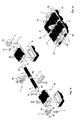
- Figures 1a and 1b such type of known connecting means.
- the figure 1a shows four links 1 (1a, 1b) assembled and the figure 1b shows in exploded form different components of this assembly.
- the parts shown in black in these figures are made of rubber.
- each link 1 has two parallel holes 4 which each receive an axis 2 (a single axis is shown on the figure 1b ).
- each axis 2 thus carries two links 1a, 1b symmetrical to each other.
- Each pair of links 1 is then attached to another similar pair by means of connectors 3 which are attached to the axis 2.
- figure 1a shows such an assembly.
- each pair of links 1a, 1b is also attached to the neighboring pair by a central connector 5 (also visible figure 1b ).
- This central connector has two flanges fixed by screws and carries an extension 5a which acts as a guide tooth for the caterpillar.
- the end connectors 3 comprise two cylindrical holes 3a, 3b, intended to cap the axes 2, and connected by tabs 6a, 6b.
- a screw 7 passes through the tongues 6a, 6b and cooperates with a thread formed in one of the tongues. The tightening of this screw makes it possible to elastically bring the tabs 6a, 6b closer to one another, which causes the connector 3 to be clamped on the pins 2.
- the connector 3 and the ends of the axis may be provided with one or more flats (not shown). Such an arrangement will ensure a relative positioning of the links giving a prior flexion between successive links. This will facilitate the winding of the tracks on the gypsy, the tension pulley and the end rollers of the undercarriage.
- each axis 2 comprises two rings 8 of a coating of a synthetic material.
- the axis thus comprises three bearing surfaces 9a, 9b and 9c (which may be cylindrical or prismatic), bearing surfaces delimiting the two rings 8.
- the connectors 3 and 5 are fixed on these bearing surfaces.
- the rings 8 are made most often of rubber, either in one piece by overmolding or by threading different concentric rings glued to each other (rings called adhesives).
- These rings 8 are interposed between the axis 2 and the link 1. They allow to absorb some of the mechanical stresses received links. They also prevent metal to metal friction between the axis 2 and the link 1 during operation of the track. Indeed such friction would lead to premature wear of the axes which would cause breaks.
- the rubber crowns 8 allows to allow different deformations for the axes 2 from one link to the other during operation of the track.
- the rings 8 must not slide during operation and they support by their deformation the relative torsions of the axes 2 relative to the links 1.
- the object of the invention is to propose a connection axis making it possible to limit the heating of the synthetic crowns, which increases the lifespan of the tracks.
- the subject of the invention is an axis of connection between caterpillar links of a vehicle and the connectors of these links, which axis comprises at least one ring of a coating of a synthetic material, a ring interposed between the axis and at least one link and enabling part of the mechanical stresses received from the links to be absorbed, the axis comprising at least two bearing surfaces on either side of the ring, on which connectors are fixed, axis characterized in that it comprises at least one axial bore extending longitudinally from one bearing surface to another bearing surface, the bore being closed on both sides by closure means and enclosing a material comprising a liquid phase and making it possible to evacuate to the connectors the calories likely to accumulate at the level of the crown, the volume of this material in the liquid state being lower than the total volume of the bore to allow the circulation of the material
- the volume of material in the liquid state will be less than half of the total volume of the bore.
- the inner surface of the bore may advantageously comprise longitudinal grooves.
- At least one means for closing the bore may be removable.
- the bore containing the material may be partially under vacuum.
- the material will be chosen such that it vaporizes at a temperature of at least 20 ° C below a critical temperature Tc, defined as the temperature at which the crown may deteriorate, the vaporization of the material occurring at the hottest parts of the axis, and the material condensing in the vicinity of the connectors, a convection movement which appears inside the axis ensuring the cooling of the latter in the vicinity of the crown .
- Tc critical temperature
- the vaporizable material may be chosen from the following materials: water, alcohols, trichlorethylene, trichloroethane, tetrahydrofuran, thiols.
- the material will be a metal or a metal alloy which is liquid at a temperature of at least 20 ° C below a critical temperature Tc, that is to say a temperature at which the crown is likely to deteriorate.
- the metal or metal alloy may be selected from the following list: sodium, potassium, rubidium, gallium, cesium, mercury, sodium / potassium alloy.
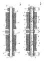
- a connecting pin 2 according to a first embodiment of the invention comprises, as the known axes, two rings 8 of a coating of a synthetic material (for example rubber). These rings 8 are interposed between the axis 2 and the links 1.
- the crowns 8 delimit on the axis 2 of the bearings 9a, 9b and 9c.
- the median span 9b receives a central connector 5 and the lateral surfaces 9a and 9c each receive an end connector 3.
- the axis 2 is tubular and therefore comprises an axial bore 10 which extends longitudinally from the span 9a to the range 9c.
- This bore 10 is closed on both sides by closure means 11 which are constituted here by threaded plugs, each cooperating with a tapping arranged on the bore 10.
- the bore 10 contains a material 12 which comprises a liquid phase.
- the material 12 does not completely fill the total volume of the bore in the liquid state. Indeed, it is necessary that the material 12 can circulate in this bore 10.
- the volume occupied by the material will preferably be less than half the volume total bore. At least one of the plugs 11 will be removable (during a part of the life of the equipment) which will introduce the material 12 or to complete its level.
- the material 12 is chosen so that it vaporizes at a temperature of at least 20 ° C below a critical temperature Tc, defined as that at which the ring 8 risk of deterioration.
- a vaporizing fluid for a temperature less than or equal to Tc-20 ° C is around 100 ° C; for example water, methanol, ethanol, other alcohols of higher molecular weight (such as isopropanol), trichlorethylene or trichloroethane, tetrahydrofuran, thiols.
- Thiols are chemical substances homologous to alcohols, in which a -SH (sulphhydryl) -terminal substitutes for the -OH termination of alcohols.
- the temperature of the peripheral zones Z2 and Z3 will increase.
- the temperature of the median zones Z1 will decrease. All temperatures becoming close to the temperature of vaporization of the liquid (ie almost 20 ° C below the critical temperature Tc).
- zone Z1 The zones are located in the figures for information only. The temperature is of course not the same throughout each zone, nor between different zones. The thermal differences will however remain moderate. The hottest parts of zone Z1 are located approximately halfway between connectors 3 and 5. The temperature decreases progressively between this median part and the ends of axis 2.
- the material 12 will vaporize (appearance of a vapor phase V 12 ) at the Z1 zones of the tube 2. This change of state leads to the absorption of calories provided by the tube, and therefore to the cooling of the zone Z1.
- the generated vapor which occupies a larger volume than the original liquid material, moves away from both sides of the zone Z1 (arrows 13) towards the colder parts of the tube 2, thus towards the zones Z2 and Z3 .
- the liquid material 12 therefore returns to the central zones Z1 where it will again vaporize. It thus appears in steady state a convection movement inside the axis which ensures its cooling in the vicinity of the crown 8.
- the axis 2 according to the invention thus constitutes a heat machine (heat pipe) which ensures the cooling of the insulating rings 8 which allows them to be maintained at a reasonable temperature and increases their service life.
- the temperature difference between zones Z1 and Z2 / Z3 at an axis can reach 40 ° C.
- the implementation of the invention makes it possible to stabilize the overall temperature of the axis at the temperature of change of state of the liquid (at least 20 ° C below the critical temperature Tc).
- This difference of at least 20 ° C was chosen to ensure in all cases a steady state operating temperature which is well below the critical temperature Tc.
- the axis 2 proposed by the invention thus constitutes a heat pipe in which a fluid spontaneously circulates in equilibrium between its liquid and vapor phases.
- the "heat engine” of this heat pipe consists of the phase changes and the absorption - release of the associated latent heats.
- the main heat exchanges occur at the end of the line, which means on the walls of zones Z1 and Z2-Z3.
- the incoming heat flow (Z1 side) and the outgoing thermal flow (Z2-Z3 side) will be balanced by increasing the internal pressure and the temperature (up to the level of the liquid state change temperature), until that equal flow is achieved.
- the material 12 will be chosen according to the critical temperature Tc of the ring 8.
- the material 12 will be placed in the bore 10 under a partial vacuum. Such an arrangement facilitates convection movements, the gas phase is not then hindered by a complementary air mass.
- the partial vacuum also allows a rapid engagement of the vaporization-condensation phenomenon because, at low pressure, the boiling temperatures are lowered considerably.
- This initial vacuum will be chosen sufficient to guarantee acceptable thermal levels in the "internal pressure - temperature change of state” pairs that will appear (the vaporization does indeed inevitably increase the internal pressure to the bore).
- the figure 5 shows a section of an axis 2 which thus comprises grooves 15 V-shaped profile, grooves evenly distributed angularly about the axis of the bore 10 (here eight grooves). It is of course possible to make grooves having another profile shape (U-shaped for example).
- the grooves 15 also make it possible to increase the heat exchange surface between the liquid 12 and the axis 2.
- the U-shape of the grooves is moreover the shape giving the largest exchange surface.
- the figure 6 shows another embodiment of the invention which differs from the previous in that the axis 2 comprises two bores 10a and 10b separated by a partition 16 made of a thermally conductive material.
- the partition 16 is located at the center connector 5.
- Each bore 10a, 10b is closed by a specific plug 11 and it contains a material 12.
- This embodiment makes it possible to improve the heat transfer at the middle connector 5.
- This partition 16, as well as the plugs 11, may be provided with pins or other prominences increasing its heat exchange surface.
- the partition 16 is in fact then a cold zone which is in good thermal contact with the connector 5.
- the axis 2 then comprises two separate thermal machines, one for each link 1 integral with the same axis 2.
- the convection movements directed towards the median connector 5 are stopped by a cold partition 16 on which condensation is more easily caused.
- material 12 not a vaporizable material but a metal (or a metal alloy) which is liquid at a temperature at least 20 ° C below the critical temperature Tc (temperature at which the crown may deteriorate).
- the physical phenomenon used for cooling is no longer the change of state of a material but the simple thermal conduction, activated by the advance movements of the vehicle.
- the thermal conductivity of the liquid metals is indeed important and the agitation to which they are subjected during the movement of the caterpillar facilitates the evacuation of calories between the hot zones Z1 and the cold zones Z2 and Z3.
- the bore 10 must then have a total and definitive seal, with its end caps set up (welded). It will also be ensured of the chemical compatibility of the metal or the alloy introduced with the material constituting the axis 2 and plugs 11.
- the vacuum can be achieved in the bore 10 which will prevent the oxidation problems of the metals in question. It will also be possible to achieve a partial vacuum of the bore and using an inert gas with respect to metals or alloys.
Landscapes
- Engineering & Computer Science (AREA)
- Chemical & Material Sciences (AREA)
- Combustion & Propulsion (AREA)
- Transportation (AREA)
- Mechanical Engineering (AREA)
- Pressure Vessels And Lids Thereof (AREA)
- Connector Housings Or Holding Contact Members (AREA)
- Heat Treatment Of Articles (AREA)
- Transmissions By Endless Flexible Members (AREA)
- Vehicle Waterproofing, Decoration, And Sanitation Devices (AREA)
- Fittings On The Vehicle Exterior For Carrying Loads, And Devices For Holding Or Mounting Articles (AREA)
- Road Signs Or Road Markings (AREA)
Applications Claiming Priority (1)
| Application Number | Priority Date | Filing Date | Title |
|---|---|---|---|
| FR0807143A FR2939757B1 (fr) | 2008-12-16 | 2008-12-16 | Axe de liaison pour maillons de chenille de vehicule |
Publications (2)
| Publication Number | Publication Date |
|---|---|
| EP2199192A1 true EP2199192A1 (de) | 2010-06-23 |
| EP2199192B1 EP2199192B1 (de) | 2011-08-03 |
Family
ID=40810226
Family Applications (1)
| Application Number | Title | Priority Date | Filing Date |
|---|---|---|---|
| EP09290921A Active EP2199192B1 (de) | 2008-12-16 | 2009-12-09 | Verbindungsachse für Raupenkettenglieder eines Fahrzeugs |
Country Status (4)
| Country | Link |
|---|---|
| US (1) | US8292375B2 (de) |
| EP (1) | EP2199192B1 (de) |
| AT (1) | ATE518731T1 (de) |
| FR (1) | FR2939757B1 (de) |
Families Citing this family (1)
| Publication number | Priority date | Publication date | Assignee | Title |
|---|---|---|---|---|
| RU183776U1 (ru) * | 2018-04-11 | 2018-10-02 | Общество с ограниченной ответственностью "Концепт" | Палец гусеничной цепи |
Citations (4)
| Publication number | Priority date | Publication date | Assignee | Title |
|---|---|---|---|---|
| US2391907A (en) * | 1942-04-20 | 1946-01-01 | Harry A Knox | Track shoe |
| US4139241A (en) | 1977-01-06 | 1979-02-13 | Ing. Ludwig Pietzsch | Endless track |
| FR2537939A1 (fr) * | 1982-12-18 | 1984-06-22 | Diehl Gmbh & Co | Dispositif de liaison d'elements de chenilles pour vehicules chenilles |
| US4700992A (en) | 1985-07-03 | 1987-10-20 | General Dynamics Land Systems, Inc. | Endless track and components thereof for track laying vehicle |
Family Cites Families (5)
| Publication number | Priority date | Publication date | Assignee | Title |
|---|---|---|---|---|
| DE3127104C2 (de) * | 1981-07-09 | 1985-05-23 | Intertractor Viehmann GmbH & Co, 5820 Gevelsberg | Scharniergelenk einer Gleiskette |
| US4840438A (en) * | 1985-07-03 | 1989-06-20 | General Dynamics Land Systems, Inc. | Pin and bushing assembly for shoe assembly of track laying vehicle |
| US4892365A (en) * | 1988-05-04 | 1990-01-09 | Szakacs Geza C | Track unit for use in a vehicle track assembly |
| DE19929961A1 (de) * | 1999-06-29 | 2001-01-04 | Intertractor Gmbh | Gleiskette für Kettenfahrzeuge |
| US7850256B2 (en) * | 2008-10-24 | 2010-12-14 | Deere & Company | Dual-bushing track chain cartridge |
-
2008
- 2008-12-16 FR FR0807143A patent/FR2939757B1/fr not_active Expired - Fee Related
-
2009
- 2009-12-09 EP EP09290921A patent/EP2199192B1/de active Active
- 2009-12-09 AT AT09290921T patent/ATE518731T1/de not_active IP Right Cessation
- 2009-12-15 US US12/654,250 patent/US8292375B2/en active Active
Patent Citations (4)
| Publication number | Priority date | Publication date | Assignee | Title |
|---|---|---|---|---|
| US2391907A (en) * | 1942-04-20 | 1946-01-01 | Harry A Knox | Track shoe |
| US4139241A (en) | 1977-01-06 | 1979-02-13 | Ing. Ludwig Pietzsch | Endless track |
| FR2537939A1 (fr) * | 1982-12-18 | 1984-06-22 | Diehl Gmbh & Co | Dispositif de liaison d'elements de chenilles pour vehicules chenilles |
| US4700992A (en) | 1985-07-03 | 1987-10-20 | General Dynamics Land Systems, Inc. | Endless track and components thereof for track laying vehicle |
Also Published As
| Publication number | Publication date |
|---|---|
| EP2199192B1 (de) | 2011-08-03 |
| US8292375B2 (en) | 2012-10-23 |
| ATE518731T1 (de) | 2011-08-15 |
| FR2939757B1 (fr) | 2010-12-17 |
| FR2939757A1 (fr) | 2010-06-18 |
| US20100148576A1 (en) | 2010-06-17 |
Similar Documents
| Publication | Publication Date | Title |
|---|---|---|
| EP0012050B1 (de) | Gekühlte Elektrode zur Herstellung des Kontakts mit einer Metallschmelze | |
| CA1259367A (fr) | Dispositif de connexion electrique destine a etre place en paroi d'un four metallurgique a courant continu | |
| FR2984472A1 (fr) | Dispositif de regulation thermique passif | |
| EP3516217B1 (de) | Wasserstoffverdichter mit metallhydrid | |
| EP1264999A2 (de) | Thermisch gesteuerter Entriegelungsmechanismus | |
| EP2440806A1 (de) | Stossdämpfer und mit solch einem stossdämpfer versehenes fahrwerk | |
| LU84681A1 (fr) | Frein a disque a performances elevees | |
| EP2199192B1 (de) | Verbindungsachse für Raupenkettenglieder eines Fahrzeugs | |
| FR2556804A1 (fr) | Element de suspension hydropneumatique de vehicule, notamment suspension oleopneumatique destinee a equiper des vehicules lourds, et suspension constituee de tels elements | |
| FR2776762A1 (fr) | Dispositif de liaison thermique pour machine cryogenique | |
| EP2044381B1 (de) | Wärmeübertrager | |
| WO2022171968A1 (fr) | Dispositif de suspension pour roue avant directrice de type mono-pivot équipé d'une biellette de couple et d'un support d'étrier spécifique permettant le montage d'éléments standards | |
| CA2198566C (fr) | Cylindre de coulee d'une installation de coulee continue sur un ou entre deux cylindres | |
| FR2572873A1 (fr) | Electrode de paroi pour four metallurgique electrique a courant continu | |
| FR2785025A1 (fr) | Plaque de dressage pour un embrayage a friction, groupe structurel comprenant une telle plaque, et volant d'inertie presentant ses caracteristiques | |
| EP3217137A1 (de) | Vorrichtung zur thermischen kühlung eines objekts mithilfe einer kühlquelle, wie etwa einem kühlmittelbad | |
| FR2500581A1 (fr) | Refroidisseur cryogenique a liaison thermique perfectionnee | |
| FR2630161A1 (fr) | Thermostat de securite pour un circuit de liquide de refroidissement, notamment dans un moteur | |
| EP0025021A1 (de) | Vorrichtung zur kryochirurgischen Behandlung mit einer Wärmeaustauscher-Einheit mit hohem Wirkungsgrad | |
| EP0307308B1 (de) | Einrichtung zum Verhindern von Waffenrohr-Ausbiegungen | |
| FR2752287A1 (fr) | Dispositif de liaison a temperature cryogenique | |
| FR3116313A1 (fr) | Ressort élastique à spires, système d’amortissement et procédé de fabrication associés | |
| WO2014006055A1 (fr) | Raccord rotulaire a dissipation thermique par radiation | |
| WO2023118180A1 (fr) | Unité de stockage de fluide cryogénique | |
| EP0285491B1 (de) | Tiefsttemperaturkälteanlage |
Legal Events
| Date | Code | Title | Description |
|---|---|---|---|
| PUAI | Public reference made under article 153(3) epc to a published international application that has entered the european phase |
Free format text: ORIGINAL CODE: 0009012 |
|
| AK | Designated contracting states |
Kind code of ref document: A1 Designated state(s): AT BE BG CH CY CZ DE DK EE ES FI FR GB GR HR HU IE IS IT LI LT LU LV MC MK MT NL NO PL PT RO SE SI SK SM TR |
|
| AX | Request for extension of the european patent |
Extension state: AL BA RS |
|
| 17P | Request for examination filed |
Effective date: 20101223 |
|
| GRAP | Despatch of communication of intention to grant a patent |
Free format text: ORIGINAL CODE: EPIDOSNIGR1 |
|
| RIC1 | Information provided on ipc code assigned before grant |
Ipc: B62D 55/21 20060101AFI20110118BHEP |
|
| GRAS | Grant fee paid |
Free format text: ORIGINAL CODE: EPIDOSNIGR3 |
|
| GRAA | (expected) grant |
Free format text: ORIGINAL CODE: 0009210 |
|
| AK | Designated contracting states |
Kind code of ref document: B1 Designated state(s): AT BE BG CH CY CZ DE DK EE ES FI FR GB GR HR HU IE IS IT LI LT LU LV MC MK MT NL NO PL PT RO SE SI SK SM TR |
|
| REG | Reference to a national code |
Ref country code: GB Ref legal event code: FG4D Free format text: NOT ENGLISH |
|
| REG | Reference to a national code |
Ref country code: CH Ref legal event code: EP |
|
| REG | Reference to a national code |
Ref country code: IE Ref legal event code: FG4D Free format text: LANGUAGE OF EP DOCUMENT: FRENCH |
|
| REG | Reference to a national code |
Ref country code: DE Ref legal event code: R096 Ref document number: 602009001991 Country of ref document: DE Effective date: 20111006 |
|
| REG | Reference to a national code |
Ref country code: NL Ref legal event code: VDEP Effective date: 20110803 |
|
| LTIE | Lt: invalidation of european patent or patent extension |
Effective date: 20110803 |
|
| PG25 | Lapsed in a contracting state [announced via postgrant information from national office to epo] |
Ref country code: NO Free format text: LAPSE BECAUSE OF FAILURE TO SUBMIT A TRANSLATION OF THE DESCRIPTION OR TO PAY THE FEE WITHIN THE PRESCRIBED TIME-LIMIT Effective date: 20111103 Ref country code: PT Free format text: LAPSE BECAUSE OF FAILURE TO SUBMIT A TRANSLATION OF THE DESCRIPTION OR TO PAY THE FEE WITHIN THE PRESCRIBED TIME-LIMIT Effective date: 20111205 Ref country code: IS Free format text: LAPSE BECAUSE OF FAILURE TO SUBMIT A TRANSLATION OF THE DESCRIPTION OR TO PAY THE FEE WITHIN THE PRESCRIBED TIME-LIMIT Effective date: 20111203 Ref country code: FI Free format text: LAPSE BECAUSE OF FAILURE TO SUBMIT A TRANSLATION OF THE DESCRIPTION OR TO PAY THE FEE WITHIN THE PRESCRIBED TIME-LIMIT Effective date: 20110803 Ref country code: NL Free format text: LAPSE BECAUSE OF FAILURE TO SUBMIT A TRANSLATION OF THE DESCRIPTION OR TO PAY THE FEE WITHIN THE PRESCRIBED TIME-LIMIT Effective date: 20110803 Ref country code: HR Free format text: LAPSE BECAUSE OF FAILURE TO SUBMIT A TRANSLATION OF THE DESCRIPTION OR TO PAY THE FEE WITHIN THE PRESCRIBED TIME-LIMIT Effective date: 20110803 Ref country code: SE Free format text: LAPSE BECAUSE OF FAILURE TO SUBMIT A TRANSLATION OF THE DESCRIPTION OR TO PAY THE FEE WITHIN THE PRESCRIBED TIME-LIMIT Effective date: 20110803 Ref country code: LT Free format text: LAPSE BECAUSE OF FAILURE TO SUBMIT A TRANSLATION OF THE DESCRIPTION OR TO PAY THE FEE WITHIN THE PRESCRIBED TIME-LIMIT Effective date: 20110803 |
|
| REG | Reference to a national code |
Ref country code: AT Ref legal event code: MK05 Ref document number: 518731 Country of ref document: AT Kind code of ref document: T Effective date: 20110803 |
|
| PG25 | Lapsed in a contracting state [announced via postgrant information from national office to epo] |
Ref country code: SI Free format text: LAPSE BECAUSE OF FAILURE TO SUBMIT A TRANSLATION OF THE DESCRIPTION OR TO PAY THE FEE WITHIN THE PRESCRIBED TIME-LIMIT Effective date: 20110803 Ref country code: AT Free format text: LAPSE BECAUSE OF FAILURE TO SUBMIT A TRANSLATION OF THE DESCRIPTION OR TO PAY THE FEE WITHIN THE PRESCRIBED TIME-LIMIT Effective date: 20110803 Ref country code: PL Free format text: LAPSE BECAUSE OF FAILURE TO SUBMIT A TRANSLATION OF THE DESCRIPTION OR TO PAY THE FEE WITHIN THE PRESCRIBED TIME-LIMIT Effective date: 20110803 Ref country code: CY Free format text: LAPSE BECAUSE OF FAILURE TO SUBMIT A TRANSLATION OF THE DESCRIPTION OR TO PAY THE FEE WITHIN THE PRESCRIBED TIME-LIMIT Effective date: 20110803 Ref country code: LV Free format text: LAPSE BECAUSE OF FAILURE TO SUBMIT A TRANSLATION OF THE DESCRIPTION OR TO PAY THE FEE WITHIN THE PRESCRIBED TIME-LIMIT Effective date: 20110803 Ref country code: GR Free format text: LAPSE BECAUSE OF FAILURE TO SUBMIT A TRANSLATION OF THE DESCRIPTION OR TO PAY THE FEE WITHIN THE PRESCRIBED TIME-LIMIT Effective date: 20111104 |
|
| REG | Reference to a national code |
Ref country code: IE Ref legal event code: FD4D |
|
| PG25 | Lapsed in a contracting state [announced via postgrant information from national office to epo] |
Ref country code: IE Free format text: LAPSE BECAUSE OF FAILURE TO SUBMIT A TRANSLATION OF THE DESCRIPTION OR TO PAY THE FEE WITHIN THE PRESCRIBED TIME-LIMIT Effective date: 20110803 Ref country code: CZ Free format text: LAPSE BECAUSE OF FAILURE TO SUBMIT A TRANSLATION OF THE DESCRIPTION OR TO PAY THE FEE WITHIN THE PRESCRIBED TIME-LIMIT Effective date: 20110803 Ref country code: SK Free format text: LAPSE BECAUSE OF FAILURE TO SUBMIT A TRANSLATION OF THE DESCRIPTION OR TO PAY THE FEE WITHIN THE PRESCRIBED TIME-LIMIT Effective date: 20110803 |
|
| PG25 | Lapsed in a contracting state [announced via postgrant information from national office to epo] |
Ref country code: EE Free format text: LAPSE BECAUSE OF FAILURE TO SUBMIT A TRANSLATION OF THE DESCRIPTION OR TO PAY THE FEE WITHIN THE PRESCRIBED TIME-LIMIT Effective date: 20110803 Ref country code: RO Free format text: LAPSE BECAUSE OF FAILURE TO SUBMIT A TRANSLATION OF THE DESCRIPTION OR TO PAY THE FEE WITHIN THE PRESCRIBED TIME-LIMIT Effective date: 20110803 Ref country code: IT Free format text: LAPSE BECAUSE OF FAILURE TO SUBMIT A TRANSLATION OF THE DESCRIPTION OR TO PAY THE FEE WITHIN THE PRESCRIBED TIME-LIMIT Effective date: 20110803 |
|
| PLBE | No opposition filed within time limit |
Free format text: ORIGINAL CODE: 0009261 |
|
| STAA | Information on the status of an ep patent application or granted ep patent |
Free format text: STATUS: NO OPPOSITION FILED WITHIN TIME LIMIT |
|
| PG25 | Lapsed in a contracting state [announced via postgrant information from national office to epo] |
Ref country code: DK Free format text: LAPSE BECAUSE OF FAILURE TO SUBMIT A TRANSLATION OF THE DESCRIPTION OR TO PAY THE FEE WITHIN THE PRESCRIBED TIME-LIMIT Effective date: 20110803 |
|
| BERE | Be: lapsed |
Owner name: NEXTER SYSTEMS Effective date: 20111231 |
|
| 26N | No opposition filed |
Effective date: 20120504 |
|
| PG25 | Lapsed in a contracting state [announced via postgrant information from national office to epo] |
Ref country code: MC Free format text: LAPSE BECAUSE OF NON-PAYMENT OF DUE FEES Effective date: 20111231 |
|
| REG | Reference to a national code |
Ref country code: DE Ref legal event code: R097 Ref document number: 602009001991 Country of ref document: DE Effective date: 20120504 |
|
| PG25 | Lapsed in a contracting state [announced via postgrant information from national office to epo] |
Ref country code: BE Free format text: LAPSE BECAUSE OF NON-PAYMENT OF DUE FEES Effective date: 20111231 |
|
| PG25 | Lapsed in a contracting state [announced via postgrant information from national office to epo] |
Ref country code: MK Free format text: LAPSE BECAUSE OF FAILURE TO SUBMIT A TRANSLATION OF THE DESCRIPTION OR TO PAY THE FEE WITHIN THE PRESCRIBED TIME-LIMIT Effective date: 20110803 Ref country code: MT Free format text: LAPSE BECAUSE OF FAILURE TO SUBMIT A TRANSLATION OF THE DESCRIPTION OR TO PAY THE FEE WITHIN THE PRESCRIBED TIME-LIMIT Effective date: 20110803 |
|
| PG25 | Lapsed in a contracting state [announced via postgrant information from national office to epo] |
Ref country code: SM Free format text: LAPSE BECAUSE OF FAILURE TO SUBMIT A TRANSLATION OF THE DESCRIPTION OR TO PAY THE FEE WITHIN THE PRESCRIBED TIME-LIMIT Effective date: 20110803 Ref country code: ES Free format text: LAPSE BECAUSE OF FAILURE TO SUBMIT A TRANSLATION OF THE DESCRIPTION OR TO PAY THE FEE WITHIN THE PRESCRIBED TIME-LIMIT Effective date: 20111114 |
|
| PG25 | Lapsed in a contracting state [announced via postgrant information from national office to epo] |
Ref country code: LU Free format text: LAPSE BECAUSE OF NON-PAYMENT OF DUE FEES Effective date: 20111209 |
|
| PG25 | Lapsed in a contracting state [announced via postgrant information from national office to epo] |
Ref country code: BG Free format text: LAPSE BECAUSE OF FAILURE TO SUBMIT A TRANSLATION OF THE DESCRIPTION OR TO PAY THE FEE WITHIN THE PRESCRIBED TIME-LIMIT Effective date: 20111103 |
|
| PG25 | Lapsed in a contracting state [announced via postgrant information from national office to epo] |
Ref country code: TR Free format text: LAPSE BECAUSE OF FAILURE TO SUBMIT A TRANSLATION OF THE DESCRIPTION OR TO PAY THE FEE WITHIN THE PRESCRIBED TIME-LIMIT Effective date: 20110803 |
|
| PG25 | Lapsed in a contracting state [announced via postgrant information from national office to epo] |
Ref country code: HU Free format text: LAPSE BECAUSE OF FAILURE TO SUBMIT A TRANSLATION OF THE DESCRIPTION OR TO PAY THE FEE WITHIN THE PRESCRIBED TIME-LIMIT Effective date: 20110803 |
|
| REG | Reference to a national code |
Ref country code: CH Ref legal event code: PL |
|
| PG25 | Lapsed in a contracting state [announced via postgrant information from national office to epo] |
Ref country code: LI Free format text: LAPSE BECAUSE OF NON-PAYMENT OF DUE FEES Effective date: 20131231 Ref country code: CH Free format text: LAPSE BECAUSE OF NON-PAYMENT OF DUE FEES Effective date: 20131231 |
|
| REG | Reference to a national code |
Ref country code: FR Ref legal event code: PLFP Year of fee payment: 7 |
|
| REG | Reference to a national code |
Ref country code: FR Ref legal event code: PLFP Year of fee payment: 8 |
|
| REG | Reference to a national code |
Ref country code: FR Ref legal event code: PLFP Year of fee payment: 9 |
|
| PGFP | Annual fee paid to national office [announced via postgrant information from national office to epo] |
Ref country code: DE Payment date: 20251126 Year of fee payment: 17 |
|
| PGFP | Annual fee paid to national office [announced via postgrant information from national office to epo] |
Ref country code: GB Payment date: 20251119 Year of fee payment: 17 |
|
| PGFP | Annual fee paid to national office [announced via postgrant information from national office to epo] |
Ref country code: FR Payment date: 20251120 Year of fee payment: 17 |