EP2199196B1 - Befestigungsvorrichtung für eine Zündschaltsperre - Google Patents
Befestigungsvorrichtung für eine Zündschaltsperre Download PDFInfo
- Publication number
- EP2199196B1 EP2199196B1 EP09173222A EP09173222A EP2199196B1 EP 2199196 B1 EP2199196 B1 EP 2199196B1 EP 09173222 A EP09173222 A EP 09173222A EP 09173222 A EP09173222 A EP 09173222A EP 2199196 B1 EP2199196 B1 EP 2199196B1
- Authority
- EP
- European Patent Office
- Prior art keywords
- fastening device
- tubular body
- adjusting member
- head pipe
- circular recess
- Prior art date
- Legal status (The legal status is an assumption and is not a legal conclusion. Google has not performed a legal analysis and makes no representation as to the accuracy of the status listed.)
- Not-in-force
Links
Images




Classifications
-
- B—PERFORMING OPERATIONS; TRANSPORTING
- B62—LAND VEHICLES FOR TRAVELLING OTHERWISE THAN ON RAILS
- B62K—CYCLES; CYCLE FRAMES; CYCLE STEERING DEVICES; RIDER-OPERATED TERMINAL CONTROLS SPECIALLY ADAPTED FOR CYCLES; CYCLE AXLE SUSPENSIONS; CYCLE SIDECARS, FORECARS, OR THE LIKE
- B62K21/00—Steering devices
-
- B—PERFORMING OPERATIONS; TRANSPORTING
- B62—LAND VEHICLES FOR TRAVELLING OTHERWISE THAN ON RAILS
- B62K—CYCLES; CYCLE FRAMES; CYCLE STEERING DEVICES; RIDER-OPERATED TERMINAL CONTROLS SPECIALLY ADAPTED FOR CYCLES; CYCLE AXLE SUSPENSIONS; CYCLE SIDECARS, FORECARS, OR THE LIKE
- B62K11/00—Motorcycles, engine-assisted cycles or motor scooters with one or two wheels
Definitions
- the present invention relates to a fastening device, especially to a fastening device for attaching an ignition switch lock to a head pipe of a motorcycle.
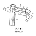
- a conventional fastening device (93) is used to attach an ignition switch lock (92) of a motorcycle to a head pipe (91) of the motorcycle (90).
- the fastening device (93) can be fabricated by punching press.
- the fastening device (93) has a first side mounted on the head pipe (91) and a second side forming a connecting end (94). The connecting end (94) allows the ignition switch lock (92) to be fixed thereon.
- a keyhole of an ignition switch lock may be arranged in different positions of a plastic body shell of the motorcycle. Therefore, the ignition switch lock may be disposed in different positions relative to the head pipe (91) so the fastening device (93) may not be suitable for all types of motorcycles.
- the structure of the fastening device (93) needs to be re-designed, such as the fastening device (93) shown in Figs. 9 to 11 .
- DE-U-202004017996 also discloses a conventional fastening device.
- the present invention provides a fastening device for an ignition switch look in order to mitigate or obviate the aforementioned problems.
- the main objective of the present invention is to provide a fastening device for ignition switch locks that is suitable for different kinds of motorcycles.
- the fastening device is adapted to be mounted on a head pipe of a motorcycle for attaching an ignition switch lock to the head pipe and comprises an adjusting member and a connector.
- the adjusting member is a hollow tubular body having a proximal end and a distal end.
- the proximal end is connected to an outer wall of the head pipe.
- the connector has a connecting body, a circular recess and a shaft hole.
- the connecting body has an outer surface adapted to be connected to the ignition switch lock.
- the circular recess is formed on an inner surface of the connecting body, corresponds to and receives the distal end of the adjusting member.
- the shaft hole is formed through the outer surface of the connecting body and communicates with the circular recess.
- the fastening device can be structurally changed for a specific motorcycle.
- the ignition switch lock can be fixed by the fastening device in a predetermined position based on motorcycle design.
- the adjusting member cooperating with the connector can be widely used in many types of motorcycles. Standardization of the fastening device simplifies motorcycle design and reduces retooling and time costs and associated costs of new motorcycle designs.
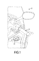
- a motorcycle (2) may be a motorbike, a scooter, a motorized tricycle or the like and generally has a body shell.
- the body shell has a mounting hole for mounting an ignition switch lock (5) and revealing a keyhole (51) of the ignition switch lock (5).
- the mounting hole for the ignition switch lock (5) is often arranged near a handlebar (3) of the motorcycle (2). However, exact position of the mounting hole depends on motorcycle type and design. Therefore, the position of the mounting hole that reveals the keyhole (51) differs.
- a fastening device (1) is mounted on a head pipe (4) of the motorcycle (2) for mounting an ignition switch lock (5).
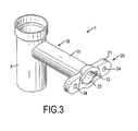
- the fastening device (1) comprises an adjusting member (10) and a connector (20).
- the adjusting member (10) is formed as a hollow tubular body (11).
- the tubular body (11) has a proximal end, a distal end (12) and an outer sidewall and may be cylindrical.
- the proximal end is connected to an outer surface of the head pipe (4).
- the distal end (12) may be circular in cross section.
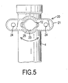
- a length of the adjusting member (10) is designed depending on motorcycle type. With further reference to Fig. 4 , the position of the adjusting member (10) relative to the head pipe (4) can be changed by rotating the adjusting member (10) before fixing the adjusting member (10) to the head pipe (4).
- the connector (20) has a connecting body (21), a circular recess (22), a shaft hole (23) and may have two fastening holes (24).
- the connecting body (21) has an inner surface and an outer surface.
- the circular recess (22) is formed on the inner surface of the connecting body (21) and corresponds to the distal end (12) of the adjusting member (10).
- the distal end (12) is adapted to extend into the circular recess (22).
- angle of the connector (20) can be changed to a desired angle by rotating the connector (20) around an axis of the adjusting member (10) before fixing the connector (20) on the adjusting member (10).
- the shaft hole (23) is formed through the outer surface of the connecting body (21) and communicates with the circular recess (22).
- the shaft hole (23) allows insertion of a shaft of the ignition switch leek (5).
- the fastening holes (24) are formed through the connecting body (21) and respectively disposed on two opposite sides of the shaft hole (23).
- the ignition switch lock (5) can be fixed to the connector (20) with multiple fasteners mounted through the fastening holes (24).
- the circular recess (22) may have a cambered inner sidewall (25) corresponding to the outer sidewall of the tubular body (11) to facilitate rotation of the connector (20) relative to the adjusting member (10).
- the fastening device (1) may further have a reinforcing rib (30) mounted on the outer sidewall of the tubular body (11).
- the reinforcing rib (30) extends along a direction opposite to the distal end (12) of the tubular body (11).
- the reinforcing rib (30) connects the adjusting member (10) and a frame of the motorcycle (2), especially the head pipe (4) of the motorcycle (2), to increase a structural stability of the adjusting member (10).
- the tubular body (11) further has multiple cutting surfaces (13).
- the cutting surfaces (13) of the tubular body (11) are formed circumferentially on the outer sidewall and make the tubular body (11) polygonal in cross section.
- the circular recess (22) further has multiple cutting surfaces (26) formed on the cambered inner sidewall (25), wherein the cutting surfaces (26) of the circular recess (22) correspond in shape to the cutting surfaces (13) of the tubular body (11).
- the connector (20) can be rotated around the axis of the adjusting member (10) to a desired angle as well before the connector (20) is fixed to the adjusting member (10).
- the connector (20) may be fixed to the adjusting member (10) by soldering.
- the fastening device (1) can be structurally changed as desired to fix the ignition switch lock (5) in a predetermined position by adjusting the length of the adjusting member (10), the position of the adjusting member (10) relative to the head pipe (4) and the angle of the connector (20).
- the fastening device (1) can be widely used in many types of motorcycles.
- the adjusting member (10) and the connector (20) both have simple structures that simplify the design and reduce the number of the molds used in the manufacturing process. Therefore, retooling costs can be reduced.
- the fastening device (1) uses the adjusting member (10) and the connector (20) to achieve design standardization and further reduce lead times and associated costs of new motorcycle designs.
Landscapes
- Engineering & Computer Science (AREA)
- Mechanical Engineering (AREA)
- Lock And Its Accessories (AREA)
- Motorcycle And Bicycle Frame (AREA)
- Steering Devices For Bicycles And Motorcycles (AREA)
Claims (8)
- Befestigungsvorrichtung (1), die dafür eingerichtet ist, an einem Steuerrohr (4) eines Motorrades (2) angebracht zu werden, um ein Zündschalterschloss (5) an dem Steuerrohr (4) zu befestigen, wobei die Befestigungsvorrichtung (1) ein Einstellelement (10) hat, das an dem Steuerrohr (4) geformt ist, wobei das Einstellelement (10) als ein hohler röhrenförmiger Korpus (11) geformt ist, der ein proximales Ende, ein distales Ende (12) und eine äußere Seitenwand hat, wobei das proximale Ende mit einer Außenwand des Steuerrohres (4) verbunden ist, dadurch gekennzeichnet, dass sie Folgendes umfasst:einen Verbinder (20), der Folgendes hat:einen Verbindungskorpus (21), der eine Innenfläche und eine Außenfläche hat, wobei die Außenfläche dafür eingerichtet ist, mit dem Zündschalterschloss (5) verbunden zu werden,eine kreisförmige Aussparung (22), die an der Innenfläche des Verbindungskorpus (21) geformt ist, wobei sie dem distalen Ende (12) des Einstellelements (10) entspricht und dasselbe aufnimmt, undein Schaftloch (23), das durch die Außenfläche des Verbindungskorpus (21) geformt und mit der kreisförmigen Aussparung (22) verbunden ist.
- Befestigungsvorrichtung nach Anspruch 1, wobei der Verbinder (20) ferner zwei Befestigungslöcher (24) hat, die durch den Verbindungskorpus (21) geformt und jeweils auf zwei entgegengesetzten Seiten des Schaftlochs (23) angeordnet sind.
- Befestigungsvorrichtung nach Anspruch 1, wobei:der röhrenförmige Korpus (11) zylindrisch ist,die äußere Seitenwand des röhrenförmigen Korpus (11) gewölbt ist unddie kreisförmige Aussparung (22) eine gewölbte innere Seitenwand (25) hat, die der äußeren Seitenwand des röhrenförmigen Korpus (11) entspricht.
- Befestigungsvorrichtung nach Anspruch 2, wobei:der röhrenförmige Korpus (11) zylindrisch ist,die äußere Seitenwand des röhrenförmigen Korpus (11) gewölbt ist unddie kreisförmige Aussparung (22) eine gewölbte innere Seitenwand (25) hat, die der äußeren Seitenwand des röhrenförmigen Korpus (11) entspricht.
- Befestigungsvorrichtung nach Anspruch 1, wobei:der röhrenförmige Korpus (11) ferner mehrere Schneidflächen (13) hat, die umlaufend an der äußeren Seitenwand des röhrenförmigen Körpers (11) geformt sind, unddie kreisförmige Aussparung (22) eine gewölbte innere Seitenwand (25) und mehrere Schneidflächen (26), die an der gewölbten inneren Seitenwand (25) geformt sind, hat, wobei die Schneidflächen (26) der kreisförmigen Aussparung (22) den Schneidflächen (13) des röhrenförmigen Korpus (11) entsprechen.
- Befestigungsvorrichtung nach Anspruch 2, wobei:der röhrenförmige Korpus (11) ferner mehrere Schneidflächen (13) hat, die umlaufend an der äußeren Seitenwand des röhrenförmigen Körpers (11) geformt sind, unddie kreisförmige Aussparung (22) eine gewölbte innere Seitenwand (25) und mehrere Schneidflächen (26), die an der gewölbten inneren Seitenwand (25) geformt sind, hat, wobei die Schneidflächen (26) der kreisförmigen Aussparung (22) den Schneidflächen (13) des röhrenförmigen Korpus (11) entsprechen.
- Befestigungsvorrichtung nach einem der Ansprüche 1 bis 6, der ferner eine Verstärkungsrippe (30) umfasst, die an der äußeren Seitenwand des röhrenförmigen Korpus (11) angebracht ist, wobei sich die Verstärkungsrippe (30) längs einer Richtung, entgegengesetzt zu dem distalen Ende (12) des röhrenförmigen Korpus (11), erstreckt.
- Befestigungsvorrichtung nach Anspruch 7, wobei die Verstärkungsrippe (30) das Einstellelement (10) und das Steuerrohr (4) des Motorrades (2) verbindet.
Applications Claiming Priority (1)
| Application Number | Priority Date | Filing Date | Title |
|---|---|---|---|
| TW097149972A TW201024151A (en) | 2008-12-22 | 2008-12-22 | Retaining device for main switch lock head |
Publications (2)
| Publication Number | Publication Date |
|---|---|
| EP2199196A1 EP2199196A1 (de) | 2010-06-23 |
| EP2199196B1 true EP2199196B1 (de) | 2011-01-26 |
Family
ID=41557427
Family Applications (1)
| Application Number | Title | Priority Date | Filing Date |
|---|---|---|---|
| EP09173222A Not-in-force EP2199196B1 (de) | 2008-12-22 | 2009-10-16 | Befestigungsvorrichtung für eine Zündschaltsperre |
Country Status (5)
| Country | Link |
|---|---|
| EP (1) | EP2199196B1 (de) |
| AT (1) | ATE496821T1 (de) |
| DE (1) | DE602009000684D1 (de) |
| ES (1) | ES2355940T3 (de) |
| TW (1) | TW201024151A (de) |
Families Citing this family (2)
| Publication number | Priority date | Publication date | Assignee | Title |
|---|---|---|---|---|
| TWI421192B (zh) * | 2011-08-11 | 2014-01-01 | Kwang Yang Motor Co | Speed locomotive structure |
| CN113212620B (zh) * | 2021-06-11 | 2022-05-03 | 浙江群英车业有限公司 | 电动平衡扭扭车 |
Family Cites Families (2)
| Publication number | Priority date | Publication date | Assignee | Title |
|---|---|---|---|---|
| JP4176610B2 (ja) * | 2003-10-15 | 2008-11-05 | 本田技研工業株式会社 | スクータ型車両 |
| FR2862601B1 (fr) * | 2003-11-20 | 2006-02-24 | Peugeot Motocycles | Ensemble de colonne de direction pour vehicule a deux roues de type scooter |
-
2008
- 2008-12-22 TW TW097149972A patent/TW201024151A/zh not_active IP Right Cessation
-
2009
- 2009-10-16 AT AT09173222T patent/ATE496821T1/de not_active IP Right Cessation
- 2009-10-16 DE DE602009000684T patent/DE602009000684D1/de active Active
- 2009-10-16 ES ES09173222T patent/ES2355940T3/es active Active
- 2009-10-16 EP EP09173222A patent/EP2199196B1/de not_active Not-in-force
Also Published As
| Publication number | Publication date |
|---|---|
| ATE496821T1 (de) | 2011-02-15 |
| EP2199196A1 (de) | 2010-06-23 |
| ES2355940T3 (es) | 2011-04-01 |
| TWI359759B (de) | 2012-03-11 |
| DE602009000684D1 (de) | 2011-03-10 |
| TW201024151A (en) | 2010-07-01 |
Similar Documents
| Publication | Publication Date | Title |
|---|---|---|
| US9227465B2 (en) | Bicycle wheel securing structure | |
| US11807326B2 (en) | Concealed bicycle lock system and setup method thereof | |
| US6609437B2 (en) | Handlebar stem structure | |
| CN102080719A (zh) | 具有按钮型换档手柄的换档杆 | |
| EP2199196A1 (de) | Befestigungsvorrichtung für eine Zündschaltsperre | |
| JP2009214756A (ja) | 自転車の折畳機構とこの折畳機構を備える自転車 | |
| JP5593251B2 (ja) | 鞍乗型車両のステアリングステムの締結構造 | |
| US20020149211A1 (en) | Door lock assembly having escutcheon with removable posts | |
| US9475534B2 (en) | Locking threadless bicycle headset | |
| US9359792B1 (en) | Combination of lock with adjustable key and core | |
| US20060156770A1 (en) | Restraining plate cooperating with a locking/unlocking control bar for use in a door lock mechanism | |
| US6405981B1 (en) | Roller type support frame structure | |
| JP2006312449A (ja) | 自動二輪車用調節可能ライザー | |
| CN217969790U (zh) | 一种车把手端堵结构 | |
| US20110061501A1 (en) | Signal lock tool | |
| JP2000336998A (ja) | U字型盗難防止装置 | |
| EP2103763B1 (de) | Rohrförmiger Griff für Türen und Fenster | |
| CN117585089B (zh) | 一种免工具拆卸把立 | |
| TWI667956B (zh) | 操作桿組裝體 | |
| CN220175523U (zh) | 一种用于助行器或轮椅的车轮组装结构 | |
| CN216242228U (zh) | 一种可以定位锁止的排挡头结构 | |
| JPH07324529A (ja) | ドア用ハンドル取付座 | |
| WO1999067125A1 (en) | Bicycle pedal crank | |
| KR102891564B1 (ko) | 팜측 사이드커버의 탈착이 편리한 낚시 릴 | |
| JP2001239858A (ja) | 車両用構造部材の取付構造 |
Legal Events
| Date | Code | Title | Description |
|---|---|---|---|
| PUAI | Public reference made under article 153(3) epc to a published international application that has entered the european phase |
Free format text: ORIGINAL CODE: 0009012 |
|
| AK | Designated contracting states |
Kind code of ref document: A1 Designated state(s): AT BE BG CH CY CZ DE DK EE ES FI FR GB GR HR HU IE IS IT LI LT LU LV MC MK MT NL NO PL PT RO SE SI SK SM TR |
|
| AX | Request for extension of the european patent |
Extension state: AL BA RS |
|
| 17P | Request for examination filed |
Effective date: 20100629 |
|
| GRAP | Despatch of communication of intention to grant a patent |
Free format text: ORIGINAL CODE: EPIDOSNIGR1 |
|
| RIC1 | Information provided on ipc code assigned before grant |
Ipc: B62K 11/00 20060101AFI20100715BHEP Ipc: B62K 21/00 20060101ALI20100715BHEP |
|
| GRAS | Grant fee paid |
Free format text: ORIGINAL CODE: EPIDOSNIGR3 |
|
| GRAA | (expected) grant |
Free format text: ORIGINAL CODE: 0009210 |
|
| AK | Designated contracting states |
Kind code of ref document: B1 Designated state(s): AT BE BG CH CY CZ DE DK EE ES FI FR GB GR HR HU IE IS IT LI LT LU LV MC MK MT NL NO PL PT RO SE SI SK SM TR |
|
| REG | Reference to a national code |
Ref country code: GB Ref legal event code: FG4D |
|
| REG | Reference to a national code |
Ref country code: CH Ref legal event code: EP |
|
| REG | Reference to a national code |
Ref country code: IE Ref legal event code: FG4D |
|
| REF | Corresponds to: |
Ref document number: 602009000684 Country of ref document: DE Date of ref document: 20110310 Kind code of ref document: P |
|
| REG | Reference to a national code |
Ref country code: DE Ref legal event code: R096 Ref document number: 602009000684 Country of ref document: DE Effective date: 20110310 |
|
| REG | Reference to a national code |
Ref country code: ES Ref legal event code: FG2A Ref document number: 2355940 Country of ref document: ES Kind code of ref document: T3 Effective date: 20110401 |
|
| REG | Reference to a national code |
Ref country code: GR Ref legal event code: EP Ref document number: 20110400615 Country of ref document: GR Effective date: 20110412 |
|
| REG | Reference to a national code |
Ref country code: NL Ref legal event code: VDEP Effective date: 20110126 |
|
| LTIE | Lt: invalidation of european patent or patent extension |
Effective date: 20110126 |
|
| PG25 | Lapsed in a contracting state [announced via postgrant information from national office to epo] |
Ref country code: LV Free format text: LAPSE BECAUSE OF FAILURE TO SUBMIT A TRANSLATION OF THE DESCRIPTION OR TO PAY THE FEE WITHIN THE PRESCRIBED TIME-LIMIT Effective date: 20110126 Ref country code: PT Free format text: LAPSE BECAUSE OF FAILURE TO SUBMIT A TRANSLATION OF THE DESCRIPTION OR TO PAY THE FEE WITHIN THE PRESCRIBED TIME-LIMIT Effective date: 20110526 Ref country code: NO Free format text: LAPSE BECAUSE OF FAILURE TO SUBMIT A TRANSLATION OF THE DESCRIPTION OR TO PAY THE FEE WITHIN THE PRESCRIBED TIME-LIMIT Effective date: 20110426 Ref country code: HR Free format text: LAPSE BECAUSE OF FAILURE TO SUBMIT A TRANSLATION OF THE DESCRIPTION OR TO PAY THE FEE WITHIN THE PRESCRIBED TIME-LIMIT Effective date: 20110126 Ref country code: SE Free format text: LAPSE BECAUSE OF FAILURE TO SUBMIT A TRANSLATION OF THE DESCRIPTION OR TO PAY THE FEE WITHIN THE PRESCRIBED TIME-LIMIT Effective date: 20110126 Ref country code: LT Free format text: LAPSE BECAUSE OF FAILURE TO SUBMIT A TRANSLATION OF THE DESCRIPTION OR TO PAY THE FEE WITHIN THE PRESCRIBED TIME-LIMIT Effective date: 20110126 |
|
| PG25 | Lapsed in a contracting state [announced via postgrant information from national office to epo] |
Ref country code: FI Free format text: LAPSE BECAUSE OF FAILURE TO SUBMIT A TRANSLATION OF THE DESCRIPTION OR TO PAY THE FEE WITHIN THE PRESCRIBED TIME-LIMIT Effective date: 20110126 Ref country code: PL Free format text: LAPSE BECAUSE OF FAILURE TO SUBMIT A TRANSLATION OF THE DESCRIPTION OR TO PAY THE FEE WITHIN THE PRESCRIBED TIME-LIMIT Effective date: 20110126 Ref country code: BG Free format text: LAPSE BECAUSE OF FAILURE TO SUBMIT A TRANSLATION OF THE DESCRIPTION OR TO PAY THE FEE WITHIN THE PRESCRIBED TIME-LIMIT Effective date: 20110426 Ref country code: AT Free format text: LAPSE BECAUSE OF FAILURE TO SUBMIT A TRANSLATION OF THE DESCRIPTION OR TO PAY THE FEE WITHIN THE PRESCRIBED TIME-LIMIT Effective date: 20110126 Ref country code: BE Free format text: LAPSE BECAUSE OF FAILURE TO SUBMIT A TRANSLATION OF THE DESCRIPTION OR TO PAY THE FEE WITHIN THE PRESCRIBED TIME-LIMIT Effective date: 20110126 Ref country code: SI Free format text: LAPSE BECAUSE OF FAILURE TO SUBMIT A TRANSLATION OF THE DESCRIPTION OR TO PAY THE FEE WITHIN THE PRESCRIBED TIME-LIMIT Effective date: 20110126 Ref country code: CY Free format text: LAPSE BECAUSE OF FAILURE TO SUBMIT A TRANSLATION OF THE DESCRIPTION OR TO PAY THE FEE WITHIN THE PRESCRIBED TIME-LIMIT Effective date: 20110126 Ref country code: NL Free format text: LAPSE BECAUSE OF FAILURE TO SUBMIT A TRANSLATION OF THE DESCRIPTION OR TO PAY THE FEE WITHIN THE PRESCRIBED TIME-LIMIT Effective date: 20110126 |
|
| PG25 | Lapsed in a contracting state [announced via postgrant information from national office to epo] |
Ref country code: EE Free format text: LAPSE BECAUSE OF FAILURE TO SUBMIT A TRANSLATION OF THE DESCRIPTION OR TO PAY THE FEE WITHIN THE PRESCRIBED TIME-LIMIT Effective date: 20110126 Ref country code: DK Free format text: LAPSE BECAUSE OF FAILURE TO SUBMIT A TRANSLATION OF THE DESCRIPTION OR TO PAY THE FEE WITHIN THE PRESCRIBED TIME-LIMIT Effective date: 20110126 |
|
| PG25 | Lapsed in a contracting state [announced via postgrant information from national office to epo] |
Ref country code: CZ Free format text: LAPSE BECAUSE OF FAILURE TO SUBMIT A TRANSLATION OF THE DESCRIPTION OR TO PAY THE FEE WITHIN THE PRESCRIBED TIME-LIMIT Effective date: 20110126 Ref country code: RO Free format text: LAPSE BECAUSE OF FAILURE TO SUBMIT A TRANSLATION OF THE DESCRIPTION OR TO PAY THE FEE WITHIN THE PRESCRIBED TIME-LIMIT Effective date: 20110126 Ref country code: SK Free format text: LAPSE BECAUSE OF FAILURE TO SUBMIT A TRANSLATION OF THE DESCRIPTION OR TO PAY THE FEE WITHIN THE PRESCRIBED TIME-LIMIT Effective date: 20110126 |
|
| PLBE | No opposition filed within time limit |
Free format text: ORIGINAL CODE: 0009261 |
|
| STAA | Information on the status of an ep patent application or granted ep patent |
Free format text: STATUS: NO OPPOSITION FILED WITHIN TIME LIMIT |
|
| 26N | No opposition filed |
Effective date: 20111027 |
|
| REG | Reference to a national code |
Ref country code: DE Ref legal event code: R097 Ref document number: 602009000684 Country of ref document: DE Effective date: 20111027 |
|
| PG25 | Lapsed in a contracting state [announced via postgrant information from national office to epo] |
Ref country code: MC Free format text: LAPSE BECAUSE OF NON-PAYMENT OF DUE FEES Effective date: 20111031 |
|
| REG | Reference to a national code |
Ref country code: IE Ref legal event code: MM4A |
|
| PG25 | Lapsed in a contracting state [announced via postgrant information from national office to epo] |
Ref country code: IE Free format text: LAPSE BECAUSE OF NON-PAYMENT OF DUE FEES Effective date: 20111016 |
|
| PG25 | Lapsed in a contracting state [announced via postgrant information from national office to epo] |
Ref country code: MK Free format text: LAPSE BECAUSE OF FAILURE TO SUBMIT A TRANSLATION OF THE DESCRIPTION OR TO PAY THE FEE WITHIN THE PRESCRIBED TIME-LIMIT Effective date: 20110126 Ref country code: MT Free format text: LAPSE BECAUSE OF FAILURE TO SUBMIT A TRANSLATION OF THE DESCRIPTION OR TO PAY THE FEE WITHIN THE PRESCRIBED TIME-LIMIT Effective date: 20110126 |
|
| PG25 | Lapsed in a contracting state [announced via postgrant information from national office to epo] |
Ref country code: SM Free format text: LAPSE BECAUSE OF FAILURE TO SUBMIT A TRANSLATION OF THE DESCRIPTION OR TO PAY THE FEE WITHIN THE PRESCRIBED TIME-LIMIT Effective date: 20110126 |
|
| PG25 | Lapsed in a contracting state [announced via postgrant information from national office to epo] |
Ref country code: LU Free format text: LAPSE BECAUSE OF NON-PAYMENT OF DUE FEES Effective date: 20111016 |
|
| PG25 | Lapsed in a contracting state [announced via postgrant information from national office to epo] |
Ref country code: IS Free format text: LAPSE BECAUSE OF FAILURE TO SUBMIT A TRANSLATION OF THE DESCRIPTION OR TO PAY THE FEE WITHIN THE PRESCRIBED TIME-LIMIT Effective date: 20110126 |
|
| PG25 | Lapsed in a contracting state [announced via postgrant information from national office to epo] |
Ref country code: TR Free format text: LAPSE BECAUSE OF FAILURE TO SUBMIT A TRANSLATION OF THE DESCRIPTION OR TO PAY THE FEE WITHIN THE PRESCRIBED TIME-LIMIT Effective date: 20110126 |
|
| PG25 | Lapsed in a contracting state [announced via postgrant information from national office to epo] |
Ref country code: HU Free format text: LAPSE BECAUSE OF FAILURE TO SUBMIT A TRANSLATION OF THE DESCRIPTION OR TO PAY THE FEE WITHIN THE PRESCRIBED TIME-LIMIT Effective date: 20110126 |
|
| REG | Reference to a national code |
Ref country code: CH Ref legal event code: PL |
|
| GBPC | Gb: european patent ceased through non-payment of renewal fee |
Effective date: 20131016 |
|
| PG25 | Lapsed in a contracting state [announced via postgrant information from national office to epo] |
Ref country code: LI Free format text: LAPSE BECAUSE OF NON-PAYMENT OF DUE FEES Effective date: 20131031 Ref country code: CH Free format text: LAPSE BECAUSE OF NON-PAYMENT OF DUE FEES Effective date: 20131031 Ref country code: GB Free format text: LAPSE BECAUSE OF NON-PAYMENT OF DUE FEES Effective date: 20131016 |
|
| REG | Reference to a national code |
Ref country code: FR Ref legal event code: PLFP Year of fee payment: 7 |
|
| REG | Reference to a national code |
Ref country code: FR Ref legal event code: PLFP Year of fee payment: 8 |
|
| REG | Reference to a national code |
Ref country code: FR Ref legal event code: PLFP Year of fee payment: 9 |
|
| REG | Reference to a national code |
Ref country code: FR Ref legal event code: PLFP Year of fee payment: 10 |
|
| PGFP | Annual fee paid to national office [announced via postgrant information from national office to epo] |
Ref country code: GR Payment date: 20200916 Year of fee payment: 12 |
|
| PGFP | Annual fee paid to national office [announced via postgrant information from national office to epo] |
Ref country code: DE Payment date: 20201009 Year of fee payment: 12 Ref country code: IT Payment date: 20201008 Year of fee payment: 12 Ref country code: ES Payment date: 20201103 Year of fee payment: 12 Ref country code: FR Payment date: 20201030 Year of fee payment: 12 |
|
| REG | Reference to a national code |
Ref country code: DE Ref legal event code: R119 Ref document number: 602009000684 Country of ref document: DE |
|
| PG25 | Lapsed in a contracting state [announced via postgrant information from national office to epo] |
Ref country code: DE Free format text: LAPSE BECAUSE OF NON-PAYMENT OF DUE FEES Effective date: 20220503 |
|
| PG25 | Lapsed in a contracting state [announced via postgrant information from national office to epo] |
Ref country code: GR Free format text: LAPSE BECAUSE OF NON-PAYMENT OF DUE FEES Effective date: 20220506 |
|
| PG25 | Lapsed in a contracting state [announced via postgrant information from national office to epo] |
Ref country code: FR Free format text: LAPSE BECAUSE OF NON-PAYMENT OF DUE FEES Effective date: 20211031 |
|
| PG25 | Lapsed in a contracting state [announced via postgrant information from national office to epo] |
Ref country code: IT Free format text: LAPSE BECAUSE OF NON-PAYMENT OF DUE FEES Effective date: 20211016 |
|
| REG | Reference to a national code |
Ref country code: ES Ref legal event code: FD2A Effective date: 20230217 |
|
| PG25 | Lapsed in a contracting state [announced via postgrant information from national office to epo] |
Ref country code: ES Free format text: LAPSE BECAUSE OF NON-PAYMENT OF DUE FEES Effective date: 20211017 |