EP2199221B1 - Machine d'étiquetage d'articles - Google Patents
Machine d'étiquetage d'articles Download PDFInfo
- Publication number
- EP2199221B1 EP2199221B1 EP10155197.6A EP10155197A EP2199221B1 EP 2199221 B1 EP2199221 B1 EP 2199221B1 EP 10155197 A EP10155197 A EP 10155197A EP 2199221 B1 EP2199221 B1 EP 2199221B1
- Authority
- EP
- European Patent Office
- Prior art keywords
- labeling
- machine according
- assembly
- elements
- carousel
- Prior art date
- Legal status (The legal status is an assumption and is not a legal conclusion. Google has not performed a legal analysis and makes no representation as to the accuracy of the status listed.)
- Expired - Lifetime
Links
Images




Classifications
-
- B—PERFORMING OPERATIONS; TRANSPORTING
- B65—CONVEYING; PACKING; STORING; HANDLING THIN OR FILAMENTARY MATERIAL
- B65C—LABELLING OR TAGGING MACHINES, APPARATUS, OR PROCESSES
- B65C9/00—Details of labelling machines or apparatus
- B65C9/0062—Interchangeable modules, e.g. applicator heads with label magazines and glue rollers
-
- B—PERFORMING OPERATIONS; TRANSPORTING
- B65—CONVEYING; PACKING; STORING; HANDLING THIN OR FILAMENTARY MATERIAL
- B65C—LABELLING OR TAGGING MACHINES, APPARATUS, OR PROCESSES
- B65C9/00—Details of labelling machines or apparatus
Definitions
- the invention relates to a machine for furnishing articles according to the preamble of claim 1, and as from WO 03/024861 A1 known.
- FIG. 1 This document shows a labeling machine with a table top on which a continuously driven carousel for passing articles to be equipped is mounted on labeling units. This tabletop also carries the mentioned labeling. A change of the labeling is time-consuming and cumbersome in this construction. Furthermore, such labeling machines build relatively large space because of the large table top.
- Fig. 4 of the same document discloses an embodiment in which the labeling units are designed as freestanding, replaceable modules with their own subframe and an associated drive.
- a fixing of the labeling is necessary.
- the labeling units are bolted to the hall floor, for example.
- this solution already provides improved handling of the labeling in the event of a change of aggregate. Nevertheless, this design still requires some effort to align and fix the labeling, which beats negative in particular with a frequent change of aggregate with respect to the changeover times.
- the invention is based on the object to provide an improved solution for easier and faster handling of labeling in Umstell.
- the unit intake is aligned once when setting up the machine exactly relative to the carousel or the transport plane of the articles to be equipped. A subsequent firm anchoring of the unit intake is on the hall floor.
- This power take-up may be tailored to the conditions prevailing at the site.
- An adjustable construction allows the most infinite alignment of the unit mount relative to the carousel with respect to the required height and / or the radial distance and / or the inclination to the transport plane.
- each first elements that engage the insertion of a labeling in the aggregate receptacle in associated second elements on the aggregate receptacle, wherein upon insertion or insertion of the labeling the interaction of the first and second elements centering and determining the position of the labeling.
- Said first and second elements may be in the form of preferably adjustable stop bodies, which limit the insertion or insertion movement of the labeling in the desired end position.
- a complementary embodiment of the first and second elements associated with the labeling unit and the unit mount is expedient, in particular by a form-fitting design, such that an automatic alignment of a labeling unit relative to the unit mount takes place when the elements are assembled until reaching the end position.
- Particularly suitable for this purpose are centering cones which engage in a form-fitting manner in correspondingly adapted centering bores.
- the height adjustment device preferably has a motor actuation, for example an electric motor.
- Fig. 1 is a part of a labeling machine in the basic structure without a labeling unit shown in perspective.
- the article to be labeled is also a continuously transporting carousel (see Fig. 6 ) not illustrated.
- the machine 1 essentially consists of a frame 2 with an approximately centrally arranged pivot bearing 9 for the carousel. At a radial distance from the pivot bearing an at least teilumfnature ring 4 is fixedly attached to the frame 2 concentric to this.
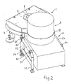
- On the ring 4 is a stationary aggregate receptacle 5 for a quick-change labeling unit 8 with connecting elements 10 (FIG. Fig. 2 ).
- the aggregate receptacle 5 is formed as a barren, to the radially outer side open tubular construction, the four at the corners of an imaginary rectangle vertically arranged height-adjustable support legs 53 (fastened to the ground) with two on the upper ends in parallel in a horizontally aligned plane with intermediate spacing support rods 54 having a circular cross-section. The spacing between them is greater than the outer housing width of a labeling unit 8 in this area.
- first elements 51 are mounted laterally projecting from the housing of the labeling unit 8 so that they meet when inserting or lowering a Etikettieraggregats from above on the support rods 54 and bear against the second elements 52 laterally. Due to the rounded to the pipe cross-section on the side facing the support rods 54 side of the first elements 51 results in a positive connection, the operating position of the labeling 8 both longitudinally and transversely fixed immovably to the support rods 54. The aggregate holder 5 transfers the entire weight of the labeling directly to the ground.
- the second elements are provided with an insertion bevel 521 at least at their upwardly pointing area.
- an integrated or external lifting device (pallet truck, hoist, etc.) is required.
- the aggregate receptacle 5 is set up when setting up the machine 1 once to the exact working position (height, radial distance, inclination to the transport plane) of a labeling. Thereafter, any labeling can be used, since the first elements 51 are all mounted in an exact same position on each unit housing.
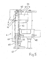
- This construction is in principle a lean version of the first embodiment and has only two support legs 63, which are also on the ring 4 - preferably form-fitting - attached. Both support legs 63 are designed as hollow tubes with a circular cross-section. At the lower end in each case a threaded bush 66 is pressed. This is penetrated by a screw spindle 65 (see sectional view in FIG Fig. 5 ). It is used for height adjustment of the ground, z. B. with screws immovably mounted feet 67. At the upper open end of the hollow tubes in each case a conically shaped seat 62 is formed for the positive reception of a Zentrierkegels 61 which is attached to the labeling unit or a plate-shaped arm 64 arranged thereon.
- Both hollow tubes are connected near the ground via a horizontal cross member 68.
- At least one horizontally extending, preferably continuously adjustable stop 69 (adjusting screw or the like) is fastened to the transverse strut for determining the inclination of a labeling unit against which the unit housing rests.
- the at least one stop 69 may, conversely, also be attached to the unit housing and be supported on the transverse strut 68.
- the two mentioned centering cones 61 are screwed to the underside of two laterally projecting from the labeling aggregate boom plates 64 and indeed at the same height with the hollow tubes 63 congruent distances.
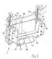
- a third embodiment of an aggregate receptacle 7 is the subject of Fig. 6 and 7 , Compared to the second embodiment described above, the main difference in an integrated lifting device 80, which allows lifting a Etikettieraggregats in different operating positions for setting different Etikettenklebe Againnchn. This can be dispensed without replacement on the previously provided in the labeling unit height adjustment.
- This third embodiment 7 has two vertically parallel aligned, attached to the ring 4 and bottom ball guides 73, the movable carriage 74 are rigidly connected via a formed of a thick-walled profiled sheet metal part cross member 75.
- a support leg 76 is formed in each case, which has a centering cone 72 on its upper side.
- an electromotive lifting drive is provided, which consists in detail of a frame-fixed geared motor 79 with a vertically oriented threaded spindle 78, which passes through a threaded hole in a rigidly attached to the crosspiece 75 block 77.
- the upper operating position can be fixed by presettable stops or limit switches, which are not shown in the travel path. But it is in connection with a Program memory the ability to retrieve different operating positions at the push of a button via a position query and set automatically by motor.
- Fig. 6 the carousel 3 of the labeling machine 1 can be seen in a schematic representation. It can be equipped with a plurality of equally spaced on a common pitch circle turntables for receiving the articles to be labeled such as bottles or the like ..
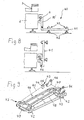
- Fig. 8 shows a fourth embodiment of an aggregate receptacle designated 40, which is not part of the invention. It is characterized by a flat underfloor construction, ie an unillustrated labeling unit can be parked with its underside on the plate-like unit mount and held in a centered relative to the carousel 3 alignment.
- a plurality of centering elements 43 are arranged offset on a horizontal plate 41, each having a centering cone 45 and a support surface 44.
- the plate 41 stands on four feet 42.
- the feet 42 and / or the centering elements 43 are individually adjustable in height by threaded fasteners to hold the labeling in the desired orientation. This setting is usually only done once.
- At the bottom of a labeling unit or its support frame are located to the centering elements 43 aligned centering holes. Via a connecting element 10 ', the plate 41 is connected to the frame 4 attached to the frame 4.
- the plate 41 may conveniently be hingedly coupled about a horizontal axis via a pivot joint 46 to the connecting element 10 ', so that the aggregate receptacle 40 when not in use by means of a handle 49 (FIGS. Fig. 9 ) from an operating position (upper illustration of Fig. 8 ) at ninety degrees upwards into an inoperative position (lower illustration of the Fig. 8 ) is foldable. This measure ensures good accessibility of the machine.
- insertion bevels in the form of raised, radially from the outside on a radially inner end position defining stop 47 leading strips 48 attached. Their mutual spacing decreases in the insertion direction, whereby a lateral advance direction of a mobile on wheels labeling unit in conjunction with attached to its underside, between the strips 48 retractable guide rollers (not shown) is possible.
- a guide roller leading in the direction of insertion hits the stop 47, the insertion movement of the labeling unit is stopped and its underside centering holes are aligned with the underlying centering elements 43 of the unit mount 40.
- the labeling unit or its support frame can have an integrated lifting device (eg hydraulically or electrically actuated) for raising and lowering.
- the aggregate receptacle 40 may be designed to be vertically movable in order to be able to bring different labeling units into different working positions (for different adhesive heights of the labels on containers).
- a motorized lifting device similar to the embodiment in the Fig. 6 and 7 come to use that can lift or lower the plate 41.
Landscapes
- Labeling Devices (AREA)
- Auxiliary Devices For And Details Of Packaging Control (AREA)
- Formation And Processing Of Food Products (AREA)
- Processing And Handling Of Plastics And Other Materials For Molding In General (AREA)
- Control And Other Processes For Unpacking Of Materials (AREA)
Claims (15)
- Machine (1) pour équiper des articles tels que des récipients ou similaires avec des étiquettes, comprenant au moins un carrousel (3) transportant les articles, et au moins un groupe d'étiquetage (8), qui est agencé de manière interchangeable à la périphérie dudit carrousel et est destiné à équiper les articles, caractérisée en ce qu'à la périphérie du carrousel (3) est agencé au moins un support d'accueil de groupe (5, 6, 7) stationnaire et directement appuyé au sol, qui est destiné à un groupe d'étiquetage (8) et permet un changement de groupes d'étiquetage quelconques, ledit support d'accueil de groupe (5, 6, 7) pouvant être ancré de manière fixe au sol et étant une structure réglable, qui permet une orientation la plus continue possible du support d'accueil de groupe par rapport au carrousel, quant à la hauteur nécessaire et/ou à la distance radiale et/ou à l'inclinaison par rapport au plan de transport.
- Machine selon la revendication 1, caractérisée en ce que le support d'accueil de groupe (5, 6, 7) est préréglé ou peut être préréglé par rapport au carrousel (3), quant à la hauteur et/ou à la distance radiale et/ou à l'inclinaison.
- Machine selon l'une des revendications 1 à 2, caractérisée en ce qu'un groupe d'étiquetage (8) est équipé, dans sa zone associée au support d'accueil de groupe (5, 6) dans l'état implanté, de premiers éléments (51, 61), qui, lors de la mise en place du groupe d'étiquetage (8), viennent en prise dans des deuxièmes éléments associés (52, 62) sur le support d'accueil de groupe, ces éléments assurant le centrage du groupe d'étiquetage et le fixant dans sa position.
- Machine selon la revendication 3, caractérisée en ce que les éléments (51, 52, 61, 62) sur le groupe d'étiquetage et le support d'accueil de groupe (5, 6) sont de configuration complémentaire.
- Machine selon la revendication 4, caractérisée en ce que les éléments (51, 52, 61, 62) sont réalisés de manière à venir mutuellement en prise par complémentarité de formes, par paires, et sont notamment réalisés sous la forme de cône de centrage (61) et d'alésage de centrage (62).
- Machine selon l'une au moins des revendications 1 à 5, caractérisée en ce que le support d'accueil de groupe (5, 6, 7) est relié au bâti (2) portant le carrousel (3), notamment à un anneau (4) entourant le bâti (2) au moins sur une partie de la périphérie.
- Machine selon l'une au moins des revendications précédentes 1 à 6, caractérisée en ce qu'au support d'accueil de groupe (7) est associé un dispositif de levage (80), notamment avec un entraînement motorisé (79).
- Machine selon la revendication 7, caractérisée en ce que le dispositif de levage (80) peut se déplacer d'une position d'accueil pour la mise en place/le retrait d'un groupe d'étiquetage, à une position de fonctionnement située plus en hauteur pour le groupe d'étiquetage, et inversement.
- Machine selon la revendication 8, caractérisée en ce que la position de fonctionnement respective pour des hauteurs d'étiquette différentes, peut être déterminée par des butées ou interrupteurs pré-réglables et pouvant être amenés dans le chemin de déplacement, ou bien par des valeurs de réglage pouvant être mémorisées/lues dans la commande de moteur du dispositif de levage motorisé (79, 80).
- Machine selon l'une au moins des revendications 7 à 9, caractérisée en ce que le dispositif de levage (80) comporte au moins un guidage vertical (73) le long duquel sont montés de manière déplaçables les éléments (72) accueillant un groupe d'étiquetage.
- Machine selon la revendication 10, caractérisée en ce que les éléments (72) sont fixés sur un support (74, 75, 76) monté sur le guidage (73).
- Machine selon l'une au moins des revendications 7 à 11, caractérisée en ce que le dispositif de levage (80) présente une broche d'entraînement (78), qui est de préférence en prise avec un support (74, 75, 76, 77) comprenant les éléments (72).
- Machine selon la revendication 12, caractérisée en ce que la broche d'entraînement (78) peut être actionnée par un moteur électrique (79), qui de préférence comporte un capteur de position de rotation (79') et est commandé par un automate programmable à mémoire.
- Machine selon l'une au moins des revendications précédentes, caractérisée en ce que le support d'accueil de groupe (5, 6, 7) peut être amené latéralement en prise avec un groupe d'étiquetage (8).
- Machine selon la revendication 14, caractérisée en ce que le support d'accueil de groupe peut être amené en prise uniquement avec un côté (6, 7) ou avec deux côtés opposés (5) d'un groupe d'étiquetage (8).
Applications Claiming Priority (3)
| Application Number | Priority Date | Filing Date | Title |
|---|---|---|---|
| DE102004002800 | 2004-01-19 | ||
| DE102004054057A DE102004054057A1 (de) | 2004-01-19 | 2004-11-05 | Maschine zum Ausstatten von Artikeln |
| EP05700720A EP1706323B9 (fr) | 2004-01-19 | 2005-01-07 | Machine d'étiquetage d'articles |
Related Parent Applications (2)
| Application Number | Title | Priority Date | Filing Date |
|---|---|---|---|
| EP05700720.5 Division | 2005-01-07 | ||
| EP05700720A Division EP1706323B9 (fr) | 2004-01-19 | 2005-01-07 | Machine d'étiquetage d'articles |
Publications (2)
| Publication Number | Publication Date |
|---|---|
| EP2199221A1 EP2199221A1 (fr) | 2010-06-23 |
| EP2199221B1 true EP2199221B1 (fr) | 2015-11-11 |
Family
ID=34744891
Family Applications (1)
| Application Number | Title | Priority Date | Filing Date |
|---|---|---|---|
| EP10155197.6A Expired - Lifetime EP2199221B1 (fr) | 2004-01-19 | 2005-01-07 | Machine d'étiquetage d'articles |
Country Status (5)
| Country | Link |
|---|---|
| EP (1) | EP2199221B1 (fr) |
| JP (1) | JP5222966B2 (fr) |
| CN (1) | CN1906091B (fr) |
| AT (1) | ATE459539T1 (fr) |
| DE (2) | DE102004054057A1 (fr) |
Families Citing this family (12)
| Publication number | Priority date | Publication date | Assignee | Title |
|---|---|---|---|---|
| DE102006007950A1 (de) | 2006-02-21 | 2007-08-30 | Khs Ag | Maschine zum Ausstatten von Flaschen oder dgl. Behälter, insbesondere Etikettiermaschine |
| ES2395742T3 (es) * | 2008-06-10 | 2013-02-14 | Sidel Holdings & Technology S.A. | Estación de etiquetado modular |
| DE102008062580B4 (de) | 2008-12-16 | 2023-02-02 | Krones Aktiengesellschaft | Maschine zum Ausstatten von Artikeln und Verfahren zur Steuerung der Maschine |
| DE102009035880B4 (de) * | 2009-08-03 | 2012-02-02 | Khs Gmbh | Behandlungsmaschine zum Behandeln von Packmitteln und Verfahren zum ausgerichteten Andocken eines Behandlungsmoduls an eine Behandlungsmaschine |
| WO2011027372A1 (fr) * | 2009-09-04 | 2011-03-10 | Kosme S.R.L. | Machine d'étiquetage |
| EP2610188B1 (fr) | 2011-12-30 | 2017-12-27 | Krones AG | Agrégat d'étiquetage |
| DE102013201768A1 (de) * | 2013-02-04 | 2014-08-07 | Krones Ag | Etikettiermaschine mit einer Hebevorrichtung |
| DE102013204123A1 (de) | 2013-03-11 | 2014-09-11 | Krones Ag | Etikettiermaschine für Gefäße |
| DE102013206667A1 (de) * | 2013-04-15 | 2014-10-16 | Krones Aktiengesellschaft | Behälterbehandlungsmaschine und Tischplatten für Behälterbehandlungsmaschinen |
| IT201900000334A1 (it) * | 2019-01-10 | 2020-07-10 | Pe Labellers Spa | Macchina a giostra per il trattamento di contenitori. |
| CN117401271A (zh) * | 2023-10-25 | 2024-01-16 | 张家港江苏科技大学产业技术研究院 | 一种双面贴标机 |
| CN119389569A (zh) * | 2024-12-09 | 2025-02-07 | 东莞市信成医疗器械科技有限公司 | 一种贴标机 |
Family Cites Families (18)
| Publication number | Priority date | Publication date | Assignee | Title |
|---|---|---|---|---|
| JPS5340160Y2 (fr) * | 1973-07-06 | 1978-09-28 | ||
| JPS571041A (en) * | 1980-06-02 | 1982-01-06 | Shibuya Kogyo Co Ltd | Labeller |
| JPS59133414U (ja) * | 1983-02-28 | 1984-09-06 | 株式会社サト− | ラベル貼付機 |
| US4479839A (en) * | 1983-03-02 | 1984-10-30 | Grand Rapids Label Company | Labeling mechanism |
| JPS61284362A (ja) * | 1985-06-10 | 1986-12-15 | Pioneer Electronic Corp | 位置決め固定機構 |
| CN1021034C (zh) * | 1988-04-09 | 1993-06-02 | Eti-Tec机械制造有限公司 | 用于物品特别是瓶状物的贴标签装置 |
| JPH0651249B2 (ja) * | 1989-03-14 | 1994-07-06 | キヤノン株式会社 | パレット供給装置の位置決め構造 |
| JPH03212335A (ja) * | 1989-12-28 | 1991-09-17 | Kanzaki Paper Mfg Co Ltd | ラベル貼付装置 |
| JPH0485296A (ja) * | 1990-07-24 | 1992-03-18 | Toshiba Corp | 機器固定機構 |
| US5141572A (en) * | 1990-09-19 | 1992-08-25 | Gerber Garment Technology, Inc. | Labelling apparatus and method for a sheet material cutting system and a supply of labels for use therewith |
| SE469226B (sv) * | 1991-10-17 | 1993-06-07 | Lars Erik Trygg | Anordning foer anbringande av etiketter paa foeremaal |
| US5624525A (en) * | 1993-08-02 | 1997-04-29 | Honda Giken Kogyo Kabushiki Kaisha | Sheet sticking apparatus |
| JPH07266281A (ja) * | 1994-03-29 | 1995-10-17 | Toshiba Corp | ロボットの交換装置 |
| DE19741476C5 (de) | 1997-09-15 | 2010-06-02 | Krones Ag | Maschine zum Behandeln von Gefäßen |
| IT1318020B1 (it) * | 2000-06-13 | 2003-07-21 | Sasib Labelling Machinery S P | Macchina di etichettaggio rotativa automatica |
| US6672356B1 (en) * | 2000-10-17 | 2004-01-06 | Kolinahr Systems, Inc. | Pallet labeler system |
| DE10145455A1 (de) * | 2001-09-14 | 2003-04-24 | Krones Ag | Maschine zum Ausstatten von Arikeln |
| DE20305967U1 (de) * | 2003-04-16 | 2003-07-03 | KHS Maschinen- und Anlagenbau AG, 44143 Dortmund | Fahrbarer Modulträger |
-
2004
- 2004-11-05 DE DE102004054057A patent/DE102004054057A1/de not_active Withdrawn
-
2005
- 2005-01-07 CN CN2005800015129A patent/CN1906091B/zh not_active Expired - Lifetime
- 2005-01-07 AT AT05700720T patent/ATE459539T1/de not_active IP Right Cessation
- 2005-01-07 EP EP10155197.6A patent/EP2199221B1/fr not_active Expired - Lifetime
- 2005-01-07 DE DE502005009127T patent/DE502005009127D1/de not_active Expired - Lifetime
-
2011
- 2011-03-09 JP JP2011051263A patent/JP5222966B2/ja not_active Expired - Lifetime
Also Published As
| Publication number | Publication date |
|---|---|
| JP5222966B2 (ja) | 2013-06-26 |
| JP2011152958A (ja) | 2011-08-11 |
| DE502005009127D1 (de) | 2010-04-15 |
| CN1906091A (zh) | 2007-01-31 |
| CN1906091B (zh) | 2012-02-08 |
| EP2199221A1 (fr) | 2010-06-23 |
| DE102004054057A1 (de) | 2005-08-04 |
| ATE459539T1 (de) | 2010-03-15 |
Similar Documents
| Publication | Publication Date | Title |
|---|---|---|
| EP1706323B9 (fr) | Machine d'étiquetage d'articles | |
| EP1412279B1 (fr) | Machine d'etiquetage | |
| EP2199221B1 (fr) | Machine d'étiquetage d'articles | |
| DE69827029T2 (de) | Maschine zum brechen von glasscheiben | |
| EP0146096B1 (fr) | Table tournante et élévatrice | |
| WO2009016250A1 (fr) | Dispositif porte-outil et dispositif pour usiner des pièces découpées plates | |
| DE19909416C1 (de) | Vorrichtung zum Aufsetzen und Heftschweißen von Profilen auf Blechplatten | |
| EP0654333A1 (fr) | Machine à travailler des pièces à usiner en bois, plastique ou similaires | |
| DE10201008B4 (de) | Wägesystem mit einem Hubsystem | |
| DE2604857B2 (de) | Honmaschine | |
| DE3642431C1 (de) | Foerdereinrichtung zum Foerdern von Kraftfahrzeugkarosserien | |
| DE3034182A1 (de) | Maschine zum beschichten von profilleisten u.dgl. | |
| DE3734510C2 (fr) | ||
| DE3834874C2 (de) | Gefäßbehandlungsmaschine | |
| DE19629285C1 (de) | Vorrichtung zum Schneiden von blattförmigem Gut | |
| DE8607859U1 (de) | Computer-Arbeitstisch | |
| DE102016216768B4 (de) | Fertigungsvorrichtung | |
| DE3432407C2 (fr) | ||
| DE3914651C2 (fr) | ||
| DE4427251C2 (de) | Presse, insbesondere Ziegelpresse | |
| DE29718221U1 (de) | Höhenverstellbares Arbeitstischsystem | |
| EP0235313B1 (fr) | Dispositif pour lever ou déposer des grands récipients transportables, par exemple des cabines, des containers ou similaires | |
| DE3943559C2 (fr) | ||
| DE4033715C1 (en) | Raised floor for building - has sports tracks formed by segments each tilted by spindle | |
| DD287461A5 (de) | Vorrichtung zum vertikalen abstellen von scheiben, insbesondere von glasscheiben |
Legal Events
| Date | Code | Title | Description |
|---|---|---|---|
| PUAI | Public reference made under article 153(3) epc to a published international application that has entered the european phase |
Free format text: ORIGINAL CODE: 0009012 |
|
| 17P | Request for examination filed |
Effective date: 20100302 |
|
| AC | Divisional application: reference to earlier application |
Ref document number: 1706323 Country of ref document: EP Kind code of ref document: P |
|
| AK | Designated contracting states |
Kind code of ref document: A1 Designated state(s): AT BE BG CH CY CZ DE DK EE ES FI FR GB GR HU IE IS IT LI LT LU MC NL PL PT RO SE SI SK TR |
|
| AX | Request for extension of the european patent |
Extension state: AL BA HR LV MK YU |
|
| 17Q | First examination report despatched |
Effective date: 20130517 |
|
| GRAP | Despatch of communication of intention to grant a patent |
Free format text: ORIGINAL CODE: EPIDOSNIGR1 |
|
| INTG | Intention to grant announced |
Effective date: 20150625 |
|
| GRAS | Grant fee paid |
Free format text: ORIGINAL CODE: EPIDOSNIGR3 |
|
| GRAA | (expected) grant |
Free format text: ORIGINAL CODE: 0009210 |
|
| AC | Divisional application: reference to earlier application |
Ref document number: 1706323 Country of ref document: EP Kind code of ref document: P |
|
| AK | Designated contracting states |
Kind code of ref document: B1 Designated state(s): AT BE BG CH CY CZ DE DK EE ES FI FR GB GR HU IE IS IT LI LT LU MC NL PL PT RO SE SI SK TR |
|
| REG | Reference to a national code |
Ref country code: GB Ref legal event code: FG4D Free format text: NOT ENGLISH |
|
| REG | Reference to a national code |
Ref country code: CH Ref legal event code: EP |
|
| REG | Reference to a national code |
Ref country code: IE Ref legal event code: FG4D Free format text: LANGUAGE OF EP DOCUMENT: GERMAN |
|
| REG | Reference to a national code |
Ref country code: FR Ref legal event code: PLFP Year of fee payment: 12 |
|
| REG | Reference to a national code |
Ref country code: AT Ref legal event code: REF Ref document number: 760305 Country of ref document: AT Kind code of ref document: T Effective date: 20151215 |
|
| REG | Reference to a national code |
Ref country code: DE Ref legal event code: R096 Ref document number: 502005015012 Country of ref document: DE |
|
| REG | Reference to a national code |
Ref country code: LT Ref legal event code: MG4D |
|
| REG | Reference to a national code |
Ref country code: NL Ref legal event code: MP Effective date: 20160211 |
|
| PG25 | Lapsed in a contracting state [announced via postgrant information from national office to epo] |
Ref country code: NL Free format text: LAPSE BECAUSE OF FAILURE TO SUBMIT A TRANSLATION OF THE DESCRIPTION OR TO PAY THE FEE WITHIN THE PRESCRIBED TIME-LIMIT Effective date: 20151111 Ref country code: ES Free format text: LAPSE BECAUSE OF FAILURE TO SUBMIT A TRANSLATION OF THE DESCRIPTION OR TO PAY THE FEE WITHIN THE PRESCRIBED TIME-LIMIT Effective date: 20151111 Ref country code: LT Free format text: LAPSE BECAUSE OF FAILURE TO SUBMIT A TRANSLATION OF THE DESCRIPTION OR TO PAY THE FEE WITHIN THE PRESCRIBED TIME-LIMIT Effective date: 20151111 Ref country code: IS Free format text: LAPSE BECAUSE OF FAILURE TO SUBMIT A TRANSLATION OF THE DESCRIPTION OR TO PAY THE FEE WITHIN THE PRESCRIBED TIME-LIMIT Effective date: 20160311 |
|
| PG25 | Lapsed in a contracting state [announced via postgrant information from national office to epo] |
Ref country code: PL Free format text: LAPSE BECAUSE OF FAILURE TO SUBMIT A TRANSLATION OF THE DESCRIPTION OR TO PAY THE FEE WITHIN THE PRESCRIBED TIME-LIMIT Effective date: 20151111 Ref country code: FI Free format text: LAPSE BECAUSE OF FAILURE TO SUBMIT A TRANSLATION OF THE DESCRIPTION OR TO PAY THE FEE WITHIN THE PRESCRIBED TIME-LIMIT Effective date: 20151111 Ref country code: SE Free format text: LAPSE BECAUSE OF FAILURE TO SUBMIT A TRANSLATION OF THE DESCRIPTION OR TO PAY THE FEE WITHIN THE PRESCRIBED TIME-LIMIT Effective date: 20151111 Ref country code: GR Free format text: LAPSE BECAUSE OF FAILURE TO SUBMIT A TRANSLATION OF THE DESCRIPTION OR TO PAY THE FEE WITHIN THE PRESCRIBED TIME-LIMIT Effective date: 20160212 Ref country code: BE Free format text: LAPSE BECAUSE OF NON-PAYMENT OF DUE FEES Effective date: 20160131 Ref country code: PT Free format text: LAPSE BECAUSE OF FAILURE TO SUBMIT A TRANSLATION OF THE DESCRIPTION OR TO PAY THE FEE WITHIN THE PRESCRIBED TIME-LIMIT Effective date: 20160311 |
|
| PG25 | Lapsed in a contracting state [announced via postgrant information from national office to epo] |
Ref country code: CZ Free format text: LAPSE BECAUSE OF FAILURE TO SUBMIT A TRANSLATION OF THE DESCRIPTION OR TO PAY THE FEE WITHIN THE PRESCRIBED TIME-LIMIT Effective date: 20151111 |
|
| REG | Reference to a national code |
Ref country code: DE Ref legal event code: R097 Ref document number: 502005015012 Country of ref document: DE |
|
| PG25 | Lapsed in a contracting state [announced via postgrant information from national office to epo] |
Ref country code: LU Free format text: LAPSE BECAUSE OF FAILURE TO SUBMIT A TRANSLATION OF THE DESCRIPTION OR TO PAY THE FEE WITHIN THE PRESCRIBED TIME-LIMIT Effective date: 20160107 Ref country code: EE Free format text: LAPSE BECAUSE OF FAILURE TO SUBMIT A TRANSLATION OF THE DESCRIPTION OR TO PAY THE FEE WITHIN THE PRESCRIBED TIME-LIMIT Effective date: 20151111 Ref country code: SK Free format text: LAPSE BECAUSE OF FAILURE TO SUBMIT A TRANSLATION OF THE DESCRIPTION OR TO PAY THE FEE WITHIN THE PRESCRIBED TIME-LIMIT Effective date: 20151111 Ref country code: RO Free format text: LAPSE BECAUSE OF FAILURE TO SUBMIT A TRANSLATION OF THE DESCRIPTION OR TO PAY THE FEE WITHIN THE PRESCRIBED TIME-LIMIT Effective date: 20151111 Ref country code: DK Free format text: LAPSE BECAUSE OF FAILURE TO SUBMIT A TRANSLATION OF THE DESCRIPTION OR TO PAY THE FEE WITHIN THE PRESCRIBED TIME-LIMIT Effective date: 20151111 |
|
| REG | Reference to a national code |
Ref country code: CH Ref legal event code: PL |
|
| PLBE | No opposition filed within time limit |
Free format text: ORIGINAL CODE: 0009261 |
|
| STAA | Information on the status of an ep patent application or granted ep patent |
Free format text: STATUS: NO OPPOSITION FILED WITHIN TIME LIMIT |
|
| PG25 | Lapsed in a contracting state [announced via postgrant information from national office to epo] |
Ref country code: MC Free format text: LAPSE BECAUSE OF FAILURE TO SUBMIT A TRANSLATION OF THE DESCRIPTION OR TO PAY THE FEE WITHIN THE PRESCRIBED TIME-LIMIT Effective date: 20151111 |
|
| 26N | No opposition filed |
Effective date: 20160812 |
|
| GBPC | Gb: european patent ceased through non-payment of renewal fee |
Effective date: 20160211 |
|
| PG25 | Lapsed in a contracting state [announced via postgrant information from national office to epo] |
Ref country code: LI Free format text: LAPSE BECAUSE OF NON-PAYMENT OF DUE FEES Effective date: 20160131 Ref country code: CH Free format text: LAPSE BECAUSE OF NON-PAYMENT OF DUE FEES Effective date: 20160131 |
|
| REG | Reference to a national code |
Ref country code: IE Ref legal event code: MM4A |
|
| PG25 | Lapsed in a contracting state [announced via postgrant information from national office to epo] |
Ref country code: SI Free format text: LAPSE BECAUSE OF FAILURE TO SUBMIT A TRANSLATION OF THE DESCRIPTION OR TO PAY THE FEE WITHIN THE PRESCRIBED TIME-LIMIT Effective date: 20151111 |
|
| REG | Reference to a national code |
Ref country code: FR Ref legal event code: PLFP Year of fee payment: 13 |
|
| PG25 | Lapsed in a contracting state [announced via postgrant information from national office to epo] |
Ref country code: IE Free format text: LAPSE BECAUSE OF NON-PAYMENT OF DUE FEES Effective date: 20160107 Ref country code: GB Free format text: LAPSE BECAUSE OF NON-PAYMENT OF DUE FEES Effective date: 20160211 |
|
| REG | Reference to a national code |
Ref country code: AT Ref legal event code: MM01 Ref document number: 760305 Country of ref document: AT Kind code of ref document: T Effective date: 20160107 |
|
| PG25 | Lapsed in a contracting state [announced via postgrant information from national office to epo] |
Ref country code: AT Free format text: LAPSE BECAUSE OF NON-PAYMENT OF DUE FEES Effective date: 20160107 |
|
| REG | Reference to a national code |
Ref country code: FR Ref legal event code: PLFP Year of fee payment: 14 |
|
| PG25 | Lapsed in a contracting state [announced via postgrant information from national office to epo] |
Ref country code: CY Free format text: LAPSE BECAUSE OF FAILURE TO SUBMIT A TRANSLATION OF THE DESCRIPTION OR TO PAY THE FEE WITHIN THE PRESCRIBED TIME-LIMIT Effective date: 20151111 Ref country code: HU Free format text: LAPSE BECAUSE OF FAILURE TO SUBMIT A TRANSLATION OF THE DESCRIPTION OR TO PAY THE FEE WITHIN THE PRESCRIBED TIME-LIMIT; INVALID AB INITIO Effective date: 20050107 |
|
| PG25 | Lapsed in a contracting state [announced via postgrant information from national office to epo] |
Ref country code: TR Free format text: LAPSE BECAUSE OF FAILURE TO SUBMIT A TRANSLATION OF THE DESCRIPTION OR TO PAY THE FEE WITHIN THE PRESCRIBED TIME-LIMIT Effective date: 20151111 |
|
| PG25 | Lapsed in a contracting state [announced via postgrant information from national office to epo] |
Ref country code: BG Free format text: LAPSE BECAUSE OF FAILURE TO SUBMIT A TRANSLATION OF THE DESCRIPTION OR TO PAY THE FEE WITHIN THE PRESCRIBED TIME-LIMIT Effective date: 20151111 |
|
| P01 | Opt-out of the competence of the unified patent court (upc) registered |
Effective date: 20230523 |
|
| PGFP | Annual fee paid to national office [announced via postgrant information from national office to epo] |
Ref country code: FR Payment date: 20231212 Year of fee payment: 20 |
|
| PGFP | Annual fee paid to national office [announced via postgrant information from national office to epo] |
Ref country code: DE Payment date: 20231205 Year of fee payment: 20 |
|
| PGFP | Annual fee paid to national office [announced via postgrant information from national office to epo] |
Ref country code: IT Payment date: 20231212 Year of fee payment: 20 |
|
| REG | Reference to a national code |
Ref country code: DE Ref legal event code: R071 Ref document number: 502005015012 Country of ref document: DE |