EP2199244B1 - Ascenseur hydraulique - Google Patents
Ascenseur hydraulique Download PDFInfo
- Publication number
- EP2199244B1 EP2199244B1 EP09179422A EP09179422A EP2199244B1 EP 2199244 B1 EP2199244 B1 EP 2199244B1 EP 09179422 A EP09179422 A EP 09179422A EP 09179422 A EP09179422 A EP 09179422A EP 2199244 B1 EP2199244 B1 EP 2199244B1
- Authority
- EP
- European Patent Office
- Prior art keywords
- fixed
- cylinder
- tubular riser
- piston
- cabin
- Prior art date
- Legal status (The legal status is an assumption and is not a legal conclusion. Google has not performed a legal analysis and makes no representation as to the accuracy of the status listed.)
- Not-in-force
Links
- 239000012530 fluid Substances 0.000 claims abstract description 15
- 238000004891 communication Methods 0.000 claims abstract description 6
- 238000004873 anchoring Methods 0.000 claims abstract description 5
- 238000007599 discharging Methods 0.000 claims abstract description 3
- 230000002093 peripheral effect Effects 0.000 claims 1
- 108010066057 cabin-1 Proteins 0.000 description 11
- 238000009434 installation Methods 0.000 description 2
- 238000011144 upstream manufacturing Methods 0.000 description 2
- 238000013459 approach Methods 0.000 description 1
- 238000013016 damping Methods 0.000 description 1
- 238000006073 displacement reaction Methods 0.000 description 1
- 230000005484 gravity Effects 0.000 description 1
- 239000010720 hydraulic oil Substances 0.000 description 1
- 238000000034 method Methods 0.000 description 1
- 238000005457 optimization Methods 0.000 description 1
- 238000005086 pumping Methods 0.000 description 1
Images


Classifications
-
- B—PERFORMING OPERATIONS; TRANSPORTING
- B66—HOISTING; LIFTING; HAULING
- B66B—ELEVATORS; ESCALATORS OR MOVING WALKWAYS
- B66B9/00—Kinds or types of lifts in, or associated with, buildings or other structures
- B66B9/04—Kinds or types of lifts in, or associated with, buildings or other structures actuated pneumatically or hydraulically
Definitions
- the present invention relates to hydraulic lifts.
- hydraulically operated lifts have been developed where the cabin is raised and lowered by means of the reciprocating displacement of a piston sliding inside a single-acting cylinder, the end of which is mounted on the floor of the pit inside the lift travel shaft.
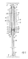
- Fig. 1 of the accompanying drawings A side elevation and partially sectioned view of an example of a known hydraulic lift is shown schematically in Fig. 1 of the accompanying drawings.
- 8 denotes a tubular cylinder which extends from the bottom floor 4 of the lift pit to about halfway along the overall height of the travel which is to be performed by the lift cabin 1.
- the document DE 3002577 A1 describes an hydraulic lift in which, via a loose pulley and a rope, a cylinder drives a car with a total load (Q + F), in which Q is the movable load and F is the weight of the car, and in which the cylinder carries a counterweight to the value of 2(Q/2 + F). Furthermore, the cylinder is guided along piston rod which is under prestress Q, is anchored in a foundation and at the same time has a bore for supplying the hydraulic fluid. Due to the movement of the cylinder along the piston rod under prestress, a smaller design of the piston rod than in the conventional arrangement with fixed cylinder and movable piston rod is obtained.
- the document JP 2001063939 A describes a movable cylinder and hydraulic elevator using it in which the lower end of a hollow upper piston rod is fixed to the upper face of a piston, and an upper side inner port is provided near there in communication with the hollow portion and an upper side outer port is provided near the upper end as a fixed point of the upper piston rod in communication with the hollow portion.
- the upper end of a hollow lower piston rod is fixed to the lower face of the piston, and an lower side inner port is provided near there in communication with the hollow portion and a lower side outer port is provided near the lower end as a fixed point of the lower piston rod in communication with the hollow portion.
- An upper cylinder chamber on the upper side of the piston and a lower cylinder chamber on the lower side of the piston are provided in a cylinder tube slidable vertically with the inner periphery being inscribed on the outer periphery of the piston.
- the document WO 00/71456 A1 describes a hydraulic elevator installation, comprising a counterweight, in which a cylinder can be displaced along a piston rod. Said piston rod can be connected in a fixed manner to sections of a building.
- the cylinder has two pressure chambers, between which hydraulic oil can be circulated, using a pump. This process displaces the cylinder along the piston rod.
- the movement of the cylinder is transmitted to a cabin by means of a cable which is guided over deflection pulleys.
- the cylinder forms part of the counterweight in relation to the cabin.
- the pump and a motor which drives the same are fixed to the cylinder in such a way that these also function as part of the counterweight.
- the document EP 0254 840 A2 describes a lifting device having a hydraulic linear motor, which is made up of a double-acting hydraulic cylinder and two stationarily anchored piston rods, connected to the piston.
- a cage is effectively connected to the hydraulic cylinder via a roller of a cable line, fastened at the upper end of the hydraulic cylinder.
- the hydraulic drive is connected via a control unit through its supply lines to connection points of the hollow-drilled piston rods, and consequently to the hydraulic cylinder.
- the overall load is compensated, at least partly, by a counterweight, which is fastened to the hydraulic cylinder.
- the object of the present invention is therefore to provide a hydraulic lift which is able to overcome the drawbacks of the known hydraulic lifts, which allows optimization of the amount of energy which is used in order to raise and lower the cabin, resulting in a considerable saving in energy which can be calculated as being equivalent to about two thirds of that of the hoisting systems of conventional hydraulic lifts, and in which, advantageously, it is possible to adjust the working stroke of the cylinder so as to ensure mechanical stoppage of the cylinder at the end surfaces, without having to provide a cylinder/piston assembly especially for each use, but by constructing it in modular fixed sizes
- the known hydraulic lift comprises a tubular riser 17 consisting of two fixed tubular stems which are fixed at their ends between the bottom part or floor 4 of the travel shaft of the lift cabin and the top part or ceiling 12 of this shaft.
- the stems of the riser 17 are connected at their ends to unions 18 and 19 for supplying and/or discharging, respectively, a hydraulic fluid, which are associated with a hydraulic circuit comprising a motor-driven pump (not shown).
- 121 denotes a fixed cylindrical piston which is positioned at the central end of the stems of the riser 17 and is concentric with said stems of the tubular riser.
- Said piston 121 also comprises a fixed diaphragm 221 which divides the internal compartment of said tubular riser 17 into two chambers 26 and 126 which are not interconnected.
- 16 denotes a movable cylinder which is positioned coaxially around these stems of the fixed riser 17 so as to create a cylindrical cavity 20 and 120 which is formed between these stems of the fixed riser 17 and this movable cylinder 16 and inside which said fixed cylindrical piston 121 is sealingly positioned for example by means of a double set of O-rings 22.
- the chambers 26 and 126 communicate, upstream and downstream of the piston 121, respectively, via radial apertures 24 and 23, with the cylindrical cavities 120 and 20 of the cylinder 16.
- the counterweight 15 is mounted on the cylinder 16, and the idle pulleys 13 are keyed onto the cylinder/counterweight assembly by means of the spindles 14.
- the movable cylinder 16 has a length equal to about half the height of the fixed riser 17 for the purposes which will be described below.
- Fig. 2 of the accompanying drawings 1 denotes the cabin of the lift.
- the ends of the cables 2 (only one of which is visible in the figures) are fixed to the structure of the cabin 1.
- Each of these cables 2 is driven, upstream of the cabin, around a first pair of idle pulleys 11 which are fixed to the top part 12 of the lift housing structure. From this first pair of pulleys 11 the cables 2 pass around a second series of idle pulleys 13, the spindles 14 of which are fixed laterally to the cylinder/counterweight assembly 15, 16 and, from these pulleys 13, the cables 2 lead to the anchoring means 204 on the ceiling 12 of the structure.
- the counterweight 15 must have a weight such as to counterbalance the weight of the lift cabin 1 plus part of carrying capacity.
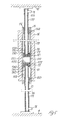
- Fig. 5 shows the hydraulic lift according to the invention, in which identical parts have the same numbers as that used in the above description.
- the central piston which is positioned at half the height and concentric with the stems 171 and 172 of the tubular riser 17, is formed in this variant by two pistons 121 and 122 each equipped with a diaphragm 221 and 222.
- a chamber 300 is therefore formed between these diaphragms 221 and 222, resulting in a reduction in the working stroke of the cylinder 16; in fact, the greater the distance between the attachment point fixed to the top part 12 and the attachment point fixed to the bottom part 4, the greater will be the size of this chamber 300 between the diaphragms 221 and 222 of the two pistons 121 and 122 and the smaller will be the extension of the cylindrical cavities 20 and 120.
- the pressure of the hydraulic fluid inside the chamber 300 must always be less than or equal to the pressure inside the cavities 20 and 120 and therefore two non-return valves 30 and 31 are positioned on the diaphragms 221 and 222. These non-return valves 30 and 31 allow the hydraulic fluid which is present inside the chamber 300 to pass into the cavities 20 and 120 should the pressure of the fluid inside the chamber 300 be greater than the pressure inside the cavities 20 and 120.
- Two cylindrical sleeves 250 and 251 are also formed in the vicinity of the ends of the cylinder 16.
- a series of radial apertures 230, 231 and 232 connecting the chamber 126 to the cylindrical cavity 20 are formed on the stem 172 in the vicinity of the piston 121, while a series of radial apertures 240, 241, 242 connecting the chamber 26 to the cylindrical cavity 120 are formed in the vicinity of the piston 122.
- the sleeve 251 will gradually obstruct the radial apertures 240, 241 and 242, damping the contact between this cylinder 16 and the piston 112.
- contact between the top end of the cylinder 16 and the piston 221 will be cushioned by gradual closing of the radial apertures 230, 231 and 232.
- Fig. 4 shows a further constructional variant of the present hydraulic lift in which the cables 2 fixed to the cabin 1, once they have passed around the pulleys 11, are fixed directly to the cylinder 16 by means of the corresponding attachment points 32.
- This variant of the present lift may be used in the case where the distance between the attachment points on the top part 12 and the bottom part 4 is greater than twice the working stroke of the lift. With this variant it is also possible to reduce the weight of the counterweight by about half.
Landscapes
- Engineering & Computer Science (AREA)
- Automation & Control Theory (AREA)
- Structural Engineering (AREA)
- Types And Forms Of Lifts (AREA)
- Valve Device For Special Equipments (AREA)
- Braking Systems And Boosters (AREA)
- Actuator (AREA)
Claims (6)
- Ascenseur hydraulique comprenant une colonne montante fixe (17) qui est montée, au niveau de ses extrémités, au moyen de raccords appropriés, entre le plancher (4) du puits de circulation de la cabine d'ascenseur et le plafond (12) dudit puits et communique, au niveau de ses extrémités, avec des embouts (18, 19) destinés à alimenter et à évacuer un fluide hydraulique ; au moins un piston cylindrique fixe (121) qui est positionné à mi chemin le long de la hauteur, de manière concentrique avec ladite colonne montante (17) ; au moins une membrane fixe (221) qui est située au niveau de la hauteur dudit piston cylindrique (121) et qui divise ladite colonne montante (17) en deux chambres (26 ; 126) qui ne sont pas interconnectées ; un vérin (16) coaxial avec ladite colonne montante (17) et définissant une cavité cylindrique (20 ; 120) qui abrite hermétiquement ledit piston cylindrique fixe (121) ; ledit vérin (16) ayant une longueur égale à environ la moitié de la longueur de ladite colonne montante (17) et ledit vérin (16) étant capable de coulisser par rapport au dit piston cylindrique fixe (121) d'une extrémité à l'autre de ladite colonne montante (17) ; des ouvertures de communication (23 ; 24) sur les deux côtés dudit piston fixe (121) capable de raccorder lesdites deux chambres (26, 126) de la colonne montante à ladite cavité cylindrique (20 ; 120) dudit vérin mobile (16) ; un moyen permettant d'alimenter en alternance le fluide sous pression dans lesdites deux chambres (26 ; 126) de la colonne montante (17) de façon à provoquer le coulissement vers le haut ou vers le bas dudit vérin mobile (16) ; au moins une première paire de poulies folles (11) qui sont, chacune, fixées à un point d'ancrage situé sur le plafond (12) du puits de circulation de la cabine d'ascenseur (1) ; au moins une seconde paire de poulies folles (13) montées sur ledit vérin mobile et fixées dans des positions diamétralement opposées l'une par rapport à l'autre ; au moins une paire de câbles (2) permettant de suspendre une cabine (1), qui sont solidement fixés au niveau d'une extrémité au plafond (12) et entraînés autour de ladite seconde paire de poulies folles (13) et à partir de celles-ci, passent autour de ladite première paire de poulies folles (11) et sont ensuite solidement fixés à la structure de la cabine (1), et un moyen (15) permettant de contrebalancer le poids de la cabine, qui sont fixés au dit vérin mobile, caractérisé en ce que ledit piston hydraulique est formé par deux pistons (121, 122), chacun étant muni d'une membrane associée (221, 222), une chambre interne (300) étant formée entre lesdits pistons (121, 122) et au moins un clapet anti-retour (30, 31) étant positionné dans chacune desdites membranes de façon à raccorder ladite chambre interne (300) aux dites chambres (26, 126) formées dans la colonne montante (17), une série d'ouvertures radiales (230, 231, 232, 240, 241, 242) étant fournies, à proximité de chacun desdits pistons (121, 122), permettant de raccorder lesdites chambres (126, 26) aux dites cavités cylindriques (20, 120), des enveloppes (250, 251) étant positionnées à proximité des extrémités du vérin mobile (16) de façon à fermer progressivement lesdites ouvertures radiales (230, 231, 232, 240, 241, 242).
- Ascenseur hydraulique selon la revendication 1, caractérisé en ce que chacun desdits pistons fixes (121, 122) comprend une enveloppe cylindrique périphérique qui divise ladite cavité cylindrique en deux chambres (20, 120).
- Ascenseur hydraulique selon la revendication 1, caractérisé en ce que ledit piston fixe (121) divise ladite cavité de la colonne montante fixe (17) en deux chambres (26 ; 126).
- Ascenseur hydraulique selon la revendication 1, caractérisé en ce que ladite enveloppe cylindrique du piston fixe (121) comprend des joints d'étanchéité (22).
- Ascenseur hydraulique selon la revendication 1, caractérisé en ce que ledit vérin mobile (16) comprend des joints d'étanchéité (25) au niveau de ses extrémités.
- Ascenseur hydraulique selon la revendication 1, caractérisé en ce que les câbles (2) fixés sur la cabine (1), une fois qu'ils sont passés autour des poulies (11) sont fixés directement au vérin (16) au moyen des points d'attache (32) correspondants.
Applications Claiming Priority (1)
| Application Number | Priority Date | Filing Date | Title |
|---|---|---|---|
| IT000106A ITGE20080106A1 (it) | 2008-12-19 | 2008-12-19 | Ascensore idraulico |
Publications (2)
| Publication Number | Publication Date |
|---|---|
| EP2199244A1 EP2199244A1 (fr) | 2010-06-23 |
| EP2199244B1 true EP2199244B1 (fr) | 2011-08-03 |
Family
ID=41682776
Family Applications (1)
| Application Number | Title | Priority Date | Filing Date |
|---|---|---|---|
| EP09179422A Not-in-force EP2199244B1 (fr) | 2008-12-19 | 2009-12-16 | Ascenseur hydraulique |
Country Status (4)
| Country | Link |
|---|---|
| EP (1) | EP2199244B1 (fr) |
| AT (1) | ATE518797T1 (fr) |
| ES (1) | ES2368609T3 (fr) |
| IT (1) | ITGE20080106A1 (fr) |
Families Citing this family (1)
| Publication number | Priority date | Publication date | Assignee | Title |
|---|---|---|---|---|
| ES2426513B1 (es) * | 2011-07-06 | 2014-07-01 | General Elevadores Xxi, S.L. | Suelo practicable para cabinas elevadoras y similares |
Family Cites Families (7)
| Publication number | Priority date | Publication date | Assignee | Title |
|---|---|---|---|---|
| DE3002577A1 (de) * | 1980-01-25 | 1981-07-30 | M.A.N. Maschinenfabrik Augsburg-Nürnberg AG, 8500 Nürnberg | Hydraulischer aufzug mit indirekt wirkendem antrieb |
| CH674641A5 (fr) * | 1986-06-11 | 1990-06-29 | Gebauer Ag | |
| CN1192967C (zh) * | 1999-05-19 | 2005-03-16 | 威图股份公司 | 液压升降机 |
| JP2001063939A (ja) * | 1999-08-31 | 2001-03-13 | Oil Drive Kogyo Kk | 可動シリンダとこれを用いた油圧エレベータ |
| GB0006033D0 (en) * | 2000-03-13 | 2000-05-03 | Ganus Eng Co Ltd | Hydraulic synchronised cylinder |
| DE10043051B4 (de) * | 2000-09-01 | 2004-12-09 | Zf Sachs Ag | Führung einer Kolbenstange für ein Kolben-Zylinder-Aggregat |
| WO2005082766A2 (fr) * | 2004-02-24 | 2005-09-09 | Anna Widmann | Entrainement hydraulique a piston fixe pour des ascenseurs |
-
2008
- 2008-12-19 IT IT000106A patent/ITGE20080106A1/it unknown
-
2009
- 2009-12-16 EP EP09179422A patent/EP2199244B1/fr not_active Not-in-force
- 2009-12-16 AT AT09179422T patent/ATE518797T1/de not_active IP Right Cessation
- 2009-12-16 ES ES09179422T patent/ES2368609T3/es active Active
Also Published As
| Publication number | Publication date |
|---|---|
| ITGE20080106A1 (it) | 2010-06-20 |
| ES2368609T3 (es) | 2011-11-18 |
| EP2199244A1 (fr) | 2010-06-23 |
| ATE518797T1 (de) | 2011-08-15 |
Similar Documents
| Publication | Publication Date | Title |
|---|---|---|
| US8944157B2 (en) | Hydro pneumatic lifting system and method | |
| KR100764299B1 (ko) | 운동 발생 및 제어용 추진 유체 동력 장치의 플런저인평형추를 가지는 엘리베이터 | |
| CN102400975B (zh) | 二级伸缩式液压缸以及液压设备 | |
| CN101638980B (zh) | 全平衡式液压传动抽油机 | |
| EP2199244B1 (fr) | Ascenseur hydraulique | |
| US6422349B1 (en) | Hydrostatic displacement drive for lifting and lowering and holding loads, in particular for lifts | |
| CA1212313A (fr) | Pompe hydraulique sur forage | |
| WO2016197834A1 (fr) | Système de levage hydraulique commandé électriquement et ascenseur de levage hydraulique commandé électriquement | |
| US20070256898A1 (en) | Drive Systems | |
| CN103269967B (zh) | 具有双层轿厢的电梯设备 | |
| CN105291264A (zh) | 辅助升降支腿、升降方法及工程机械 | |
| RU173496U1 (ru) | Гидравлический привод штангового скважинного насоса | |
| RU2547674C1 (ru) | Привод скважинного штангового насоса | |
| JP2005350173A (ja) | 油圧式エレベータの油圧シリンダ及びそれを用いた油圧回路 | |
| RU1781156C (ru) | Гидравлический лифт | |
| CA2873344A1 (fr) | Unite hydraulique de pompage mecanique a roulis | |
| CN214879888U (zh) | 一种带有高速轴向柱塞泵的升降机 | |
| CN201281053Y (zh) | 一种提升机的液压驱动控制装置 | |
| CN112794188B (zh) | 一种液压电梯的伺服油源 | |
| KR19990076668A (ko) | 데릭 내의 피스톤-실린더 조립체를 상승 또는하강시키기 위한 장치 및 방법 | |
| CN117345737A (zh) | 能量回收液压系统和机械设备 | |
| SU1084226A1 (ru) | Гидравлический подъемник | |
| KR100597980B1 (ko) | 타워식 물품저장창고의 승강구동장치 | |
| US569091A (en) | Pfmp or engine | |
| CN117404372A (zh) | 一种套管下放设备的双卷扬闭式液压系统 |
Legal Events
| Date | Code | Title | Description |
|---|---|---|---|
| PUAI | Public reference made under article 153(3) epc to a published international application that has entered the european phase |
Free format text: ORIGINAL CODE: 0009012 |
|
| AK | Designated contracting states |
Kind code of ref document: A1 Designated state(s): AT BE BG CH CY CZ DE DK EE ES FI FR GB GR HR HU IE IS IT LI LT LU LV MC MK MT NL NO PL PT RO SE SI SK SM TR |
|
| 17P | Request for examination filed |
Effective date: 20101025 |
|
| GRAP | Despatch of communication of intention to grant a patent |
Free format text: ORIGINAL CODE: EPIDOSNIGR1 |
|
| RIC1 | Information provided on ipc code assigned before grant |
Ipc: B66B 9/04 20060101AFI20110118BHEP |
|
| GRAS | Grant fee paid |
Free format text: ORIGINAL CODE: EPIDOSNIGR3 |
|
| GRAA | (expected) grant |
Free format text: ORIGINAL CODE: 0009210 |
|
| AK | Designated contracting states |
Kind code of ref document: B1 Designated state(s): AT BE BG CH CY CZ DE DK EE ES FI FR GB GR HR HU IE IS IT LI LT LU LV MC MK MT NL NO PL PT RO SE SI SK SM TR |
|
| REG | Reference to a national code |
Ref country code: GB Ref legal event code: FG4D |
|
| REG | Reference to a national code |
Ref country code: CH Ref legal event code: EP |
|
| REG | Reference to a national code |
Ref country code: IE Ref legal event code: FG4D |
|
| REG | Reference to a national code |
Ref country code: DE Ref legal event code: R096 Ref document number: 602009001975 Country of ref document: DE Effective date: 20111006 |
|
| REG | Reference to a national code |
Ref country code: ES Ref legal event code: FG2A Ref document number: 2368609 Country of ref document: ES Kind code of ref document: T3 Effective date: 20111118 |
|
| REG | Reference to a national code |
Ref country code: NL Ref legal event code: VDEP Effective date: 20110803 |
|
| LTIE | Lt: invalidation of european patent or patent extension |
Effective date: 20110803 |
|
| PG25 | Lapsed in a contracting state [announced via postgrant information from national office to epo] |
Ref country code: SE Free format text: LAPSE BECAUSE OF FAILURE TO SUBMIT A TRANSLATION OF THE DESCRIPTION OR TO PAY THE FEE WITHIN THE PRESCRIBED TIME-LIMIT Effective date: 20110803 Ref country code: HR Free format text: LAPSE BECAUSE OF FAILURE TO SUBMIT A TRANSLATION OF THE DESCRIPTION OR TO PAY THE FEE WITHIN THE PRESCRIBED TIME-LIMIT Effective date: 20110803 Ref country code: LT Free format text: LAPSE BECAUSE OF FAILURE TO SUBMIT A TRANSLATION OF THE DESCRIPTION OR TO PAY THE FEE WITHIN THE PRESCRIBED TIME-LIMIT Effective date: 20110803 Ref country code: NL Free format text: LAPSE BECAUSE OF FAILURE TO SUBMIT A TRANSLATION OF THE DESCRIPTION OR TO PAY THE FEE WITHIN THE PRESCRIBED TIME-LIMIT Effective date: 20110803 Ref country code: IS Free format text: LAPSE BECAUSE OF FAILURE TO SUBMIT A TRANSLATION OF THE DESCRIPTION OR TO PAY THE FEE WITHIN THE PRESCRIBED TIME-LIMIT Effective date: 20111203 Ref country code: FI Free format text: LAPSE BECAUSE OF FAILURE TO SUBMIT A TRANSLATION OF THE DESCRIPTION OR TO PAY THE FEE WITHIN THE PRESCRIBED TIME-LIMIT Effective date: 20110803 Ref country code: PT Free format text: LAPSE BECAUSE OF FAILURE TO SUBMIT A TRANSLATION OF THE DESCRIPTION OR TO PAY THE FEE WITHIN THE PRESCRIBED TIME-LIMIT Effective date: 20111205 Ref country code: NO Free format text: LAPSE BECAUSE OF FAILURE TO SUBMIT A TRANSLATION OF THE DESCRIPTION OR TO PAY THE FEE WITHIN THE PRESCRIBED TIME-LIMIT Effective date: 20111103 |
|
| REG | Reference to a national code |
Ref country code: AT Ref legal event code: MK05 Ref document number: 518797 Country of ref document: AT Kind code of ref document: T Effective date: 20110803 |
|
| PG25 | Lapsed in a contracting state [announced via postgrant information from national office to epo] |
Ref country code: AT Free format text: LAPSE BECAUSE OF FAILURE TO SUBMIT A TRANSLATION OF THE DESCRIPTION OR TO PAY THE FEE WITHIN THE PRESCRIBED TIME-LIMIT Effective date: 20110803 Ref country code: GR Free format text: LAPSE BECAUSE OF FAILURE TO SUBMIT A TRANSLATION OF THE DESCRIPTION OR TO PAY THE FEE WITHIN THE PRESCRIBED TIME-LIMIT Effective date: 20111104 Ref country code: CY Free format text: LAPSE BECAUSE OF FAILURE TO SUBMIT A TRANSLATION OF THE DESCRIPTION OR TO PAY THE FEE WITHIN THE PRESCRIBED TIME-LIMIT Effective date: 20110803 Ref country code: SI Free format text: LAPSE BECAUSE OF FAILURE TO SUBMIT A TRANSLATION OF THE DESCRIPTION OR TO PAY THE FEE WITHIN THE PRESCRIBED TIME-LIMIT Effective date: 20110803 Ref country code: PL Free format text: LAPSE BECAUSE OF FAILURE TO SUBMIT A TRANSLATION OF THE DESCRIPTION OR TO PAY THE FEE WITHIN THE PRESCRIBED TIME-LIMIT Effective date: 20110803 Ref country code: LV Free format text: LAPSE BECAUSE OF FAILURE TO SUBMIT A TRANSLATION OF THE DESCRIPTION OR TO PAY THE FEE WITHIN THE PRESCRIBED TIME-LIMIT Effective date: 20110803 |
|
| PG25 | Lapsed in a contracting state [announced via postgrant information from national office to epo] |
Ref country code: BE Free format text: LAPSE BECAUSE OF FAILURE TO SUBMIT A TRANSLATION OF THE DESCRIPTION OR TO PAY THE FEE WITHIN THE PRESCRIBED TIME-LIMIT Effective date: 20110803 |
|
| PG25 | Lapsed in a contracting state [announced via postgrant information from national office to epo] |
Ref country code: CZ Free format text: LAPSE BECAUSE OF FAILURE TO SUBMIT A TRANSLATION OF THE DESCRIPTION OR TO PAY THE FEE WITHIN THE PRESCRIBED TIME-LIMIT Effective date: 20110803 Ref country code: SK Free format text: LAPSE BECAUSE OF FAILURE TO SUBMIT A TRANSLATION OF THE DESCRIPTION OR TO PAY THE FEE WITHIN THE PRESCRIBED TIME-LIMIT Effective date: 20110803 |
|
| PG25 | Lapsed in a contracting state [announced via postgrant information from national office to epo] |
Ref country code: EE Free format text: LAPSE BECAUSE OF FAILURE TO SUBMIT A TRANSLATION OF THE DESCRIPTION OR TO PAY THE FEE WITHIN THE PRESCRIBED TIME-LIMIT Effective date: 20110803 Ref country code: RO Free format text: LAPSE BECAUSE OF FAILURE TO SUBMIT A TRANSLATION OF THE DESCRIPTION OR TO PAY THE FEE WITHIN THE PRESCRIBED TIME-LIMIT Effective date: 20110803 |
|
| PLBE | No opposition filed within time limit |
Free format text: ORIGINAL CODE: 0009261 |
|
| STAA | Information on the status of an ep patent application or granted ep patent |
Free format text: STATUS: NO OPPOSITION FILED WITHIN TIME LIMIT |
|
| PG25 | Lapsed in a contracting state [announced via postgrant information from national office to epo] |
Ref country code: DK Free format text: LAPSE BECAUSE OF FAILURE TO SUBMIT A TRANSLATION OF THE DESCRIPTION OR TO PAY THE FEE WITHIN THE PRESCRIBED TIME-LIMIT Effective date: 20110803 |
|
| 26N | No opposition filed |
Effective date: 20120504 |
|
| PG25 | Lapsed in a contracting state [announced via postgrant information from national office to epo] |
Ref country code: MC Free format text: LAPSE BECAUSE OF NON-PAYMENT OF DUE FEES Effective date: 20111231 |
|
| REG | Reference to a national code |
Ref country code: DE Ref legal event code: R097 Ref document number: 602009001975 Country of ref document: DE Effective date: 20120504 |
|
| REG | Reference to a national code |
Ref country code: IE Ref legal event code: MM4A |
|
| PG25 | Lapsed in a contracting state [announced via postgrant information from national office to epo] |
Ref country code: IE Free format text: LAPSE BECAUSE OF NON-PAYMENT OF DUE FEES Effective date: 20111216 |
|
| PG25 | Lapsed in a contracting state [announced via postgrant information from national office to epo] |
Ref country code: MK Free format text: LAPSE BECAUSE OF FAILURE TO SUBMIT A TRANSLATION OF THE DESCRIPTION OR TO PAY THE FEE WITHIN THE PRESCRIBED TIME-LIMIT Effective date: 20110803 Ref country code: MT Free format text: LAPSE BECAUSE OF FAILURE TO SUBMIT A TRANSLATION OF THE DESCRIPTION OR TO PAY THE FEE WITHIN THE PRESCRIBED TIME-LIMIT Effective date: 20110803 |
|
| PG25 | Lapsed in a contracting state [announced via postgrant information from national office to epo] |
Ref country code: SM Free format text: LAPSE BECAUSE OF FAILURE TO SUBMIT A TRANSLATION OF THE DESCRIPTION OR TO PAY THE FEE WITHIN THE PRESCRIBED TIME-LIMIT Effective date: 20110803 |
|
| PG25 | Lapsed in a contracting state [announced via postgrant information from national office to epo] |
Ref country code: LU Free format text: LAPSE BECAUSE OF NON-PAYMENT OF DUE FEES Effective date: 20111216 |
|
| PG25 | Lapsed in a contracting state [announced via postgrant information from national office to epo] |
Ref country code: BG Free format text: LAPSE BECAUSE OF FAILURE TO SUBMIT A TRANSLATION OF THE DESCRIPTION OR TO PAY THE FEE WITHIN THE PRESCRIBED TIME-LIMIT Effective date: 20111103 |
|
| PG25 | Lapsed in a contracting state [announced via postgrant information from national office to epo] |
Ref country code: TR Free format text: LAPSE BECAUSE OF FAILURE TO SUBMIT A TRANSLATION OF THE DESCRIPTION OR TO PAY THE FEE WITHIN THE PRESCRIBED TIME-LIMIT Effective date: 20110803 |
|
| PG25 | Lapsed in a contracting state [announced via postgrant information from national office to epo] |
Ref country code: HU Free format text: LAPSE BECAUSE OF FAILURE TO SUBMIT A TRANSLATION OF THE DESCRIPTION OR TO PAY THE FEE WITHIN THE PRESCRIBED TIME-LIMIT Effective date: 20110803 |
|
| PGFP | Annual fee paid to national office [announced via postgrant information from national office to epo] |
Ref country code: GB Payment date: 20131126 Year of fee payment: 5 Ref country code: DE Payment date: 20131107 Year of fee payment: 5 |
|
| PGFP | Annual fee paid to national office [announced via postgrant information from national office to epo] |
Ref country code: IT Payment date: 20131025 Year of fee payment: 5 Ref country code: ES Payment date: 20131125 Year of fee payment: 5 Ref country code: FR Payment date: 20131127 Year of fee payment: 5 |
|
| REG | Reference to a national code |
Ref country code: CH Ref legal event code: PL |
|
| PG25 | Lapsed in a contracting state [announced via postgrant information from national office to epo] |
Ref country code: CH Free format text: LAPSE BECAUSE OF NON-PAYMENT OF DUE FEES Effective date: 20131231 Ref country code: LI Free format text: LAPSE BECAUSE OF NON-PAYMENT OF DUE FEES Effective date: 20131231 |
|
| REG | Reference to a national code |
Ref country code: DE Ref legal event code: R119 Ref document number: 602009001975 Country of ref document: DE |
|
| GBPC | Gb: european patent ceased through non-payment of renewal fee |
Effective date: 20141216 |
|
| REG | Reference to a national code |
Ref country code: FR Ref legal event code: ST Effective date: 20150831 |
|
| PG25 | Lapsed in a contracting state [announced via postgrant information from national office to epo] |
Ref country code: GB Free format text: LAPSE BECAUSE OF NON-PAYMENT OF DUE FEES Effective date: 20141216 Ref country code: DE Free format text: LAPSE BECAUSE OF NON-PAYMENT OF DUE FEES Effective date: 20150701 |
|
| PG25 | Lapsed in a contracting state [announced via postgrant information from national office to epo] |
Ref country code: FR Free format text: LAPSE BECAUSE OF NON-PAYMENT OF DUE FEES Effective date: 20141231 |
|
| PG25 | Lapsed in a contracting state [announced via postgrant information from national office to epo] |
Ref country code: IT Free format text: LAPSE BECAUSE OF NON-PAYMENT OF DUE FEES Effective date: 20141216 |
|
| REG | Reference to a national code |
Ref country code: ES Ref legal event code: FD2A Effective date: 20160126 |
|
| PG25 | Lapsed in a contracting state [announced via postgrant information from national office to epo] |
Ref country code: ES Free format text: LAPSE BECAUSE OF NON-PAYMENT OF DUE FEES Effective date: 20141217 |