EP2199255A1 - Brennstoffzellensystem und verfahren zum anfahren des brennstoffzellensystems - Google Patents
Brennstoffzellensystem und verfahren zum anfahren des brennstoffzellensystems Download PDFInfo
- Publication number
- EP2199255A1 EP2199255A1 EP08828710A EP08828710A EP2199255A1 EP 2199255 A1 EP2199255 A1 EP 2199255A1 EP 08828710 A EP08828710 A EP 08828710A EP 08828710 A EP08828710 A EP 08828710A EP 2199255 A1 EP2199255 A1 EP 2199255A1
- Authority
- EP
- European Patent Office
- Prior art keywords
- catalyst layer
- reforming catalyst
- flow rate
- reforming
- hydrocarbon
- Prior art date
- Legal status (The legal status is an assumption and is not a legal conclusion. Google has not performed a legal analysis and makes no representation as to the accuracy of the status listed.)
- Withdrawn
Links
Images


Classifications
-
- C—CHEMISTRY; METALLURGY
- C01—INORGANIC CHEMISTRY
- C01B—NON-METALLIC ELEMENTS; COMPOUNDS THEREOF; METALLOIDS OR COMPOUNDS THEREOF NOT COVERED BY SUBCLASS C01C
- C01B3/00—Hydrogen; Gaseous mixtures containing hydrogen; Separation of hydrogen from mixtures containing it; Purification of hydrogen; Reversible storage of hydrogen
- C01B3/02—Production of hydrogen; Production of gaseous mixtures containing hydrogen
- C01B3/32—Production of hydrogen; Production of gaseous mixtures containing hydrogen by reaction of gaseous or liquid organic compounds with gasifying agents, e.g. water, carbon dioxide or air
- C01B3/34—Production of hydrogen; Production of gaseous mixtures containing hydrogen by reaction of gaseous or liquid organic compounds with gasifying agents, e.g. water, carbon dioxide or air by reaction of hydrocarbons with gasifying agents
- C01B3/38—Production of hydrogen; Production of gaseous mixtures containing hydrogen by reaction of gaseous or liquid organic compounds with gasifying agents, e.g. water, carbon dioxide or air by reaction of hydrocarbons with gasifying agents using catalysts
-
- H—ELECTRICITY
- H01—ELECTRIC ELEMENTS
- H01M—PROCESSES OR MEANS, e.g. BATTERIES, FOR THE DIRECT CONVERSION OF CHEMICAL ENERGY INTO ELECTRICAL ENERGY
- H01M8/00—Fuel cells; Manufacture thereof
- H01M8/04—Auxiliary arrangements, e.g. for control of pressure or for circulation of fluids
- H01M8/04223—Auxiliary arrangements, e.g. for control of pressure or for circulation of fluids during start-up or shut-down; Depolarisation or activation, e.g. purging; Means for short-circuiting defective fuel cells
- H01M8/04268—Heating of fuel cells during the start-up of the fuel cells
-
- C—CHEMISTRY; METALLURGY
- C01—INORGANIC CHEMISTRY
- C01B—NON-METALLIC ELEMENTS; COMPOUNDS THEREOF; METALLOIDS OR COMPOUNDS THEREOF NOT COVERED BY SUBCLASS C01C
- C01B3/00—Hydrogen; Gaseous mixtures containing hydrogen; Separation of hydrogen from mixtures containing it; Purification of hydrogen; Reversible storage of hydrogen
- C01B3/02—Production of hydrogen; Production of gaseous mixtures containing hydrogen
- C01B3/32—Production of hydrogen; Production of gaseous mixtures containing hydrogen by reaction of gaseous or liquid organic compounds with gasifying agents, e.g. water, carbon dioxide or air
- C01B3/34—Production of hydrogen; Production of gaseous mixtures containing hydrogen by reaction of gaseous or liquid organic compounds with gasifying agents, e.g. water, carbon dioxide or air by reaction of hydrocarbons with gasifying agents
- C01B3/38—Production of hydrogen; Production of gaseous mixtures containing hydrogen by reaction of gaseous or liquid organic compounds with gasifying agents, e.g. water, carbon dioxide or air by reaction of hydrocarbons with gasifying agents using catalysts
- C01B3/382—Processes with two or more reaction steps, of which at least one is catalytic, e.g. steam reforming and partial oxidation
-
- C—CHEMISTRY; METALLURGY
- C01—INORGANIC CHEMISTRY
- C01B—NON-METALLIC ELEMENTS; COMPOUNDS THEREOF; METALLOIDS OR COMPOUNDS THEREOF NOT COVERED BY SUBCLASS C01C
- C01B3/00—Hydrogen; Gaseous mixtures containing hydrogen; Separation of hydrogen from mixtures containing it; Purification of hydrogen; Reversible storage of hydrogen
- C01B3/02—Production of hydrogen; Production of gaseous mixtures containing hydrogen
- C01B3/32—Production of hydrogen; Production of gaseous mixtures containing hydrogen by reaction of gaseous or liquid organic compounds with gasifying agents, e.g. water, carbon dioxide or air
- C01B3/34—Production of hydrogen; Production of gaseous mixtures containing hydrogen by reaction of gaseous or liquid organic compounds with gasifying agents, e.g. water, carbon dioxide or air by reaction of hydrocarbons with gasifying agents
- C01B3/38—Production of hydrogen; Production of gaseous mixtures containing hydrogen by reaction of gaseous or liquid organic compounds with gasifying agents, e.g. water, carbon dioxide or air by reaction of hydrocarbons with gasifying agents using catalysts
- C01B3/386—Catalytic partial combustion
-
- H—ELECTRICITY
- H01—ELECTRIC ELEMENTS
- H01M—PROCESSES OR MEANS, e.g. BATTERIES, FOR THE DIRECT CONVERSION OF CHEMICAL ENERGY INTO ELECTRICAL ENERGY
- H01M8/00—Fuel cells; Manufacture thereof
- H01M8/04—Auxiliary arrangements, e.g. for control of pressure or for circulation of fluids
- H01M8/04223—Auxiliary arrangements, e.g. for control of pressure or for circulation of fluids during start-up or shut-down; Depolarisation or activation, e.g. purging; Means for short-circuiting defective fuel cells
- H01M8/04225—Auxiliary arrangements, e.g. for control of pressure or for circulation of fluids during start-up or shut-down; Depolarisation or activation, e.g. purging; Means for short-circuiting defective fuel cells during start-up
-
- H—ELECTRICITY
- H01—ELECTRIC ELEMENTS
- H01M—PROCESSES OR MEANS, e.g. BATTERIES, FOR THE DIRECT CONVERSION OF CHEMICAL ENERGY INTO ELECTRICAL ENERGY
- H01M8/00—Fuel cells; Manufacture thereof
- H01M8/04—Auxiliary arrangements, e.g. for control of pressure or for circulation of fluids
- H01M8/04298—Processes for controlling fuel cells or fuel cell systems
- H01M8/043—Processes for controlling fuel cells or fuel cell systems applied during specific periods
- H01M8/04302—Processes for controlling fuel cells or fuel cell systems applied during specific periods applied during start-up
-
- H—ELECTRICITY
- H01—ELECTRIC ELEMENTS
- H01M—PROCESSES OR MEANS, e.g. BATTERIES, FOR THE DIRECT CONVERSION OF CHEMICAL ENERGY INTO ELECTRICAL ENERGY
- H01M8/00—Fuel cells; Manufacture thereof
- H01M8/04—Auxiliary arrangements, e.g. for control of pressure or for circulation of fluids
- H01M8/04298—Processes for controlling fuel cells or fuel cell systems
- H01M8/04313—Processes for controlling fuel cells or fuel cell systems characterised by the detection or assessment of variables; characterised by the detection or assessment of failure or abnormal function
- H01M8/0432—Temperature; Ambient temperature
- H01M8/04373—Temperature; Ambient temperature of auxiliary devices, e.g. reformers, compressors, burners
-
- H—ELECTRICITY
- H01—ELECTRIC ELEMENTS
- H01M—PROCESSES OR MEANS, e.g. BATTERIES, FOR THE DIRECT CONVERSION OF CHEMICAL ENERGY INTO ELECTRICAL ENERGY
- H01M8/00—Fuel cells; Manufacture thereof
- H01M8/04—Auxiliary arrangements, e.g. for control of pressure or for circulation of fluids
- H01M8/04298—Processes for controlling fuel cells or fuel cell systems
- H01M8/04694—Processes for controlling fuel cells or fuel cell systems characterised by variables to be controlled
- H01M8/04746—Pressure; Flow
- H01M8/04753—Pressure; Flow of fuel cell reactants
-
- H—ELECTRICITY
- H01—ELECTRIC ELEMENTS
- H01M—PROCESSES OR MEANS, e.g. BATTERIES, FOR THE DIRECT CONVERSION OF CHEMICAL ENERGY INTO ELECTRICAL ENERGY
- H01M8/00—Fuel cells; Manufacture thereof
- H01M8/06—Combination of fuel cells with means for production of reactants or for treatment of residues
- H01M8/0606—Combination of fuel cells with means for production of reactants or for treatment of residues with means for production of gaseous reactants
- H01M8/0612—Combination of fuel cells with means for production of reactants or for treatment of residues with means for production of gaseous reactants from carbon-containing material
- H01M8/0618—Reforming processes, e.g. autothermal, partial oxidation or steam reforming
-
- H—ELECTRICITY
- H01—ELECTRIC ELEMENTS
- H01M—PROCESSES OR MEANS, e.g. BATTERIES, FOR THE DIRECT CONVERSION OF CHEMICAL ENERGY INTO ELECTRICAL ENERGY
- H01M8/00—Fuel cells; Manufacture thereof
- H01M8/24—Grouping of fuel cells, e.g. stacking of fuel cells
- H01M8/241—Grouping of fuel cells, e.g. stacking of fuel cells with solid or matrix-supported electrolytes
- H01M8/2425—High-temperature cells with solid electrolytes
-
- H—ELECTRICITY
- H01—ELECTRIC ELEMENTS
- H01M—PROCESSES OR MEANS, e.g. BATTERIES, FOR THE DIRECT CONVERSION OF CHEMICAL ENERGY INTO ELECTRICAL ENERGY
- H01M8/00—Fuel cells; Manufacture thereof
- H01M8/24—Grouping of fuel cells, e.g. stacking of fuel cells
- H01M8/2457—Grouping of fuel cells, e.g. stacking of fuel cells with both reactants being gaseous or vaporised
-
- C—CHEMISTRY; METALLURGY
- C01—INORGANIC CHEMISTRY
- C01B—NON-METALLIC ELEMENTS; COMPOUNDS THEREOF; METALLOIDS OR COMPOUNDS THEREOF NOT COVERED BY SUBCLASS C01C
- C01B2203/00—Integrated processes for the production of hydrogen or synthesis gas
- C01B2203/02—Processes for making hydrogen or synthesis gas
- C01B2203/0205—Processes for making hydrogen or synthesis gas containing a reforming step
- C01B2203/0227—Processes for making hydrogen or synthesis gas containing a reforming step containing a catalytic reforming step
- C01B2203/0233—Processes for making hydrogen or synthesis gas containing a reforming step containing a catalytic reforming step the reforming step being a steam reforming step
-
- C—CHEMISTRY; METALLURGY
- C01—INORGANIC CHEMISTRY
- C01B—NON-METALLIC ELEMENTS; COMPOUNDS THEREOF; METALLOIDS OR COMPOUNDS THEREOF NOT COVERED BY SUBCLASS C01C
- C01B2203/00—Integrated processes for the production of hydrogen or synthesis gas
- C01B2203/02—Processes for making hydrogen or synthesis gas
- C01B2203/0205—Processes for making hydrogen or synthesis gas containing a reforming step
- C01B2203/0227—Processes for making hydrogen or synthesis gas containing a reforming step containing a catalytic reforming step
- C01B2203/0244—Processes for making hydrogen or synthesis gas containing a reforming step containing a catalytic reforming step the reforming step being an autothermal reforming step, e.g. secondary reforming processes
-
- C—CHEMISTRY; METALLURGY
- C01—INORGANIC CHEMISTRY
- C01B—NON-METALLIC ELEMENTS; COMPOUNDS THEREOF; METALLOIDS OR COMPOUNDS THEREOF NOT COVERED BY SUBCLASS C01C
- C01B2203/00—Integrated processes for the production of hydrogen or synthesis gas
- C01B2203/02—Processes for making hydrogen or synthesis gas
- C01B2203/025—Processes for making hydrogen or synthesis gas containing a partial oxidation step
- C01B2203/0261—Processes for making hydrogen or synthesis gas containing a partial oxidation step containing a catalytic partial oxidation step [CPO]
-
- C—CHEMISTRY; METALLURGY
- C01—INORGANIC CHEMISTRY
- C01B—NON-METALLIC ELEMENTS; COMPOUNDS THEREOF; METALLOIDS OR COMPOUNDS THEREOF NOT COVERED BY SUBCLASS C01C
- C01B2203/00—Integrated processes for the production of hydrogen or synthesis gas
- C01B2203/06—Integration with other chemical processes
- C01B2203/066—Integration with other chemical processes with fuel cells
-
- C—CHEMISTRY; METALLURGY
- C01—INORGANIC CHEMISTRY
- C01B—NON-METALLIC ELEMENTS; COMPOUNDS THEREOF; METALLOIDS OR COMPOUNDS THEREOF NOT COVERED BY SUBCLASS C01C
- C01B2203/00—Integrated processes for the production of hydrogen or synthesis gas
- C01B2203/08—Methods of heating or cooling
- C01B2203/0805—Methods of heating the process for making hydrogen or synthesis gas
- C01B2203/085—Methods of heating the process for making hydrogen or synthesis gas by electric heating
-
- C—CHEMISTRY; METALLURGY
- C01—INORGANIC CHEMISTRY
- C01B—NON-METALLIC ELEMENTS; COMPOUNDS THEREOF; METALLOIDS OR COMPOUNDS THEREOF NOT COVERED BY SUBCLASS C01C
- C01B2203/00—Integrated processes for the production of hydrogen or synthesis gas
- C01B2203/12—Feeding the process for making hydrogen or synthesis gas
- C01B2203/1288—Evaporation of one or more of the different feed components
-
- C—CHEMISTRY; METALLURGY
- C01—INORGANIC CHEMISTRY
- C01B—NON-METALLIC ELEMENTS; COMPOUNDS THEREOF; METALLOIDS OR COMPOUNDS THEREOF NOT COVERED BY SUBCLASS C01C
- C01B2203/00—Integrated processes for the production of hydrogen or synthesis gas
- C01B2203/16—Controlling the process
- C01B2203/1604—Starting up the process
-
- C—CHEMISTRY; METALLURGY
- C01—INORGANIC CHEMISTRY
- C01B—NON-METALLIC ELEMENTS; COMPOUNDS THEREOF; METALLOIDS OR COMPOUNDS THEREOF NOT COVERED BY SUBCLASS C01C
- C01B2203/00—Integrated processes for the production of hydrogen or synthesis gas
- C01B2203/16—Controlling the process
- C01B2203/1614—Controlling the temperature
- C01B2203/1619—Measuring the temperature
-
- C—CHEMISTRY; METALLURGY
- C01—INORGANIC CHEMISTRY
- C01B—NON-METALLIC ELEMENTS; COMPOUNDS THEREOF; METALLOIDS OR COMPOUNDS THEREOF NOT COVERED BY SUBCLASS C01C
- C01B2203/00—Integrated processes for the production of hydrogen or synthesis gas
- C01B2203/16—Controlling the process
- C01B2203/169—Controlling the feed
-
- H—ELECTRICITY
- H01—ELECTRIC ELEMENTS
- H01M—PROCESSES OR MEANS, e.g. BATTERIES, FOR THE DIRECT CONVERSION OF CHEMICAL ENERGY INTO ELECTRICAL ENERGY
- H01M8/00—Fuel cells; Manufacture thereof
- H01M8/10—Fuel cells with solid electrolytes
- H01M8/12—Fuel cells with solid electrolytes operating at high temperature, e.g. with stabilised ZrO2 electrolyte
- H01M2008/1293—Fuel cells with solid oxide electrolytes
-
- Y—GENERAL TAGGING OF NEW TECHNOLOGICAL DEVELOPMENTS; GENERAL TAGGING OF CROSS-SECTIONAL TECHNOLOGIES SPANNING OVER SEVERAL SECTIONS OF THE IPC; TECHNICAL SUBJECTS COVERED BY FORMER USPC CROSS-REFERENCE ART COLLECTIONS [XRACs] AND DIGESTS
- Y02—TECHNOLOGIES OR APPLICATIONS FOR MITIGATION OR ADAPTATION AGAINST CLIMATE CHANGE
- Y02E—REDUCTION OF GREENHOUSE GAS [GHG] EMISSIONS, RELATED TO ENERGY GENERATION, TRANSMISSION OR DISTRIBUTION
- Y02E60/00—Enabling technologies; Technologies with a potential or indirect contribution to GHG emissions mitigation
- Y02E60/30—Hydrogen technology
- Y02E60/50—Fuel cells
Definitions
- the present invention relates to a fuel cell system that generates electric power using a reformed gas obtained by reforming a hydrocarbon-based fuel, such as kerosene, and a method for starting up the same.
- a solid oxide fuel cell (hereinafter sometimes referred to as SOFC) system usually includes a reformer for reforming a hydrocarbon-based fuel, such as kerosene and town gas, to generate a hydrogen-containing gas (reformed gas), and an SOFC for electrochemically reacting the reformed gas and air for electric power generation.
- a reformer for reforming a hydrocarbon-based fuel, such as kerosene and town gas, to generate a hydrogen-containing gas (reformed gas)
- SOFC solid oxide fuel cell
- the SOFC is usually operated at a high temperature of 550 to 1000°C.
- SR steam reforming
- POX partial oxidation reforming
- ATR autothermal reforming
- Patent Document 1 describes a method for starting up an SOFC system, in which the SOFC system that performs steam reforming can be efficiently performed in a short time.
- a reducing gas such as hydrogen
- a reducing gas is beforehand made to flow through the anode to prevent the oxidative degradation of the anode of the cell.
- the supply source is desirably a reformed gas obtained from a fuel.
- the SOFC When a fuel is reformed by a reformer during start-up, and the obtained reformed gas is supplied to an SOFC to prevent the degradation of the anode, for example, in the case of an indirect internal reforming SOFC, the SOFC is also simultaneously heated by heat transfer from the internal reformer. As a result, the anode is increased to the oxidative degradation temperature or higher, and when the anode is in an atmosphere of an oxidizing gas, for example, air or steam, the anode may be oxidatively degraded. Therefore, it is desired to produce the reformed gas from a stage as early as possible.
- an oxidizing gas for example, air or steam
- the present invention provides the following method and apparatus.
- step a temperatures at a plurality of points in the reforming catalyst layer at different positions along the gas flow direction are measured, and in step b, one or more flow rates of the hydrocarbon-based fuel that can be reformed in one or more of the plurality of divided regions are calculated, based on the temperatures at the plurality of points, and the total value of the calculated flow rate(s) is determined as said flow rate of the hydrocarbon-based fuel that can be reformed in the reforming catalyst layer.
- a fuel cell system including:
- the present invention provides a method for starting up a fuel cell system including a reformer having a reforming catalyst layer, and a high temperature fuel cell, in which reforming can be reliably performed from an early stage to more reliably prevent the oxidative degradation of the anode.
- the present invention provides a fuel cell system preferred for performing such a method.
- a fuel cell system used in the present invention includes a reformer for reforming a hydrocarbon-based fuel to produce a hydrogen-containing gas, and a high temperature fuel cell.
- the reformer includes a reforming catalyst layer.
- the high temperature fuel cell generates electric power, using the hydrogen-containing gas obtained from the reformer.
- the reforming catalyst layer is composed of a reforming catalyst that can promote a reforming reaction.
- the hydrogen-containing gas obtained from the reformer is referred to as a reformed gas.
- step a is performed. In other words, the temperature of the reforming catalyst layer is increased, while the temperature of the reforming catalyst layer is measured. The temperature measurement and the temperature increase by the step a are continued until the completion of start-up.
- an electrical heater provided in the reformer may be used as a heat source for this temperature increase.
- the temperature of the reforming catalyst layer may be increased by letting a high temperature fluid flow through the reforming catalyst layer.
- a high temperature fluid For example, steam and/or air required for reforming may be preheated as required and supplied.
- An electrical heater or a combustor, such as a burner, may be used as a heat source for this preheating.
- the fluid when a high temperature fluid is supplied from outside the fuel cell system, the fluid may be a heat source for the above-described preheating.
- the temperature of the reforming catalyst layer may be increased by combusting the hydrocarbon-based fuel in the reforming catalyst layer.
- the combustion gas is an oxidizing gas. Therefore, in terms of preventing the fuel cell from being degraded by the combustion gas flowing through the fuel cell, combustion is performed in the reforming catalyst layer when the fuel cell is at a temperature at which the fuel cell is not degraded even if the combustion gas flows through the fuel cell. For achieving this, the temperature of the fuel cell, particularly the temperature of the anode electrode, is monitored, and when the temperature becomes a temperature at which degradation may occur, the above combustion may be stopped.
- the temperature of the reforming catalyst layer may be increased using combustion heat generated by combusting the reformed gas.
- the temperature of the reforming catalyst layer may be increased by the heat generation.
- heat generation by a partial oxidation reforming reaction is larger than endothermic heat by a steam reforming reaction in autothermal reforming, heat is generated by the reforming.
- temperature increasing methods may be appropriately used in combination, or may be separately used depending on the situation.
- steps b and c are repeatedly performed.
- the feed rate of the hydrocarbon-based fuel to the reforming catalyst layer is increased, while the steps b and c are repeated, until the feed rate of the hydrocarbon-based fuel to the reforming catalyst layer becomes a flow rate at the completion of start-up.
- the flow rate calculated by the step b may be zero.
- the flow rate of the hydrocarbon-based fuel flow rate supplied to the reforming catalyst layer is zero, and the flow rate of the reformed gas is also zero.
- the supply of the hydrocarbon-based fuel to the reforming catalyst layer in the step c is not performed, and therefore, the supply of the reformed gas to the anode of the high temperature fuel cell is also not performed.
- the hydrocarbon-based fuel at a flow rate exceeding zero is calculated in the step b.
- the hydrocarbon-based fuel (a flow rate other than zero) is supplied to the reforming catalyst layer for the first time by the step c, the flow rate is a flow rate lower than the hydrocarbon-based fuel flow rate at the completion of start-up.
- the hydrocarbon-based fuel at the hydrocarbon-based fuel flow rate at the completion of start-up is supplied to the reforming catalyst layer.
- the hydrocarbon-based fuel at a relatively low flow rate is reformed to generate the reformed gas, in the present invention.
- the amount of reforming is increased during start-up.
- Lower temperature is enough to reform the hydrocarbon-based fuel at a lower flow rate. Therefore, a reducing gas (reformed gas) can be produced from a point of time when the temperature increase does not proceed much, that is, from a relatively early stage of start-up. By sopping this reducing gas to the anode of the fuel cell, it becomes possible to prevent the degradation of the anode from an early stage.
- Step d may be performed prior to the step c.
- steam and/or an oxygen-containing gas at a flow rate required for reforming the hydrocarbon-based fuel which is to be made to flow in the step c may be supplied to the reforming catalyst layer, prior to step c.
- the step d may be performed to beforehand supply to the reforming catalyst layer the steam and/or the oxygen-containing gas at a flow rate required for reforming the hydrocarbon-based fuel at a flow rate which is to be supplied in the next step c. Due to the step d, the hydrocarbon-based fuel supplied in the step c can be more reliably reformed. However, this is not limiting, and the steam and/or the oxygen-containing gas at the flow rate required in the step c may be supplied simultaneously with the step c.
- a steam reforming reaction that is, steam reforming or autothermal reforming
- steam is supplied to the reforming catalyst layer.
- a partial oxidation reforming reaction that is, partial oxidation reforming or autothermal reforming
- an oxygen-containing gas is supplied to the reforming catalyst layer.
- the oxygen-containing gas a gas containing oxygen may be appropriately used, but in terms of the ease of availability, air is preferred.
- reforming is gradually performed, and it is not always necessary to continuously perform the same type of reforming.
- steam reforming is preferably performed.
- a steam reforming reaction is allowed to proceed, and a partial oxidation reforming reaction is not allowed to proceed. This is because the hydrogen concentration in the reformed gas can be relatively high, prior to normal operation which is performed after the completion of start-up.
- a reforming catalyst layer that can promote a steam reforming reaction is used.
- partial oxidation reforming or autothermal reforming is preferably performed.
- partial oxidation reforming or autothermal reforming is preferably performed at an initial stage, that is, at a point of time when the hydrocarbon-based fuel at a flow rate other than zero is supplied to the reforming catalyst layer for the first time, and during a certain period following this point of time.
- partial oxidation reforming or autothermal reforming is preferably performed at an initial stage. This is because, by performing reforming which involves a partial oxidation reforming reaction, it is possible to accelerate the temperature increase.
- a reforming catalyst layer that can promote a steam reforming reaction and a partial oxidation reforming reaction is preferably used because a steam reforming reaction can be performed at the final stage of reforming, and the hydrogen concentration can be made relatively high.
- a step e of supplying the hydrocarbon-based fuel to the reforming catalyst layer to combust the hydrocarbon-based fuel may be performed in the step a, using a reforming catalyst layer that can promote combustion in addition to a reforming reaction.
- the temperature of the reforming catalyst layer may be increased by combustion in the reforming catalyst layer.
- the flow rate at this time may be lower than the flow rate of the hydrocarbon-based fuel at the completion of start-up.
- step g of supplying an oxygen-containing gas at a flow rate required for the combustion performed in the step e to the reforming catalyst layer prior to the step e.
- the combustion in the step e can be more reliably performed.
- the method for calculating the flow rate of the hydrocarbon-based fuel that can be reformed in the reforming catalyst layer, based on the measured temperature of the reforming catalyst layer, in the step b will be described below.
- the flow rate of the hydrocarbon-based fuel that can be reformed in the reforming catalyst layer refers to a flow rate such that when the hydrocarbon-based fuel at this flow rate is supplied to the reforming catalyst layer, the composition of the gas discharged from the reforming catalyst layer becomes a composition suitable to be supplied to the high temperature fuel cell.
- flow rate of the hydrocarbon-based fuel that can be reformed is sometimes referred to as "reformable flow rate.”
- the reformable flow rate in the reforming catalyst layer may be any flow rate equal to or less than the maximum value of a flow rate at which the supplied hydrocarbon-based fuel can be decomposed to a C1 compound (a compound having one carbon atom).
- the reformable flow rate in the reforming catalyst layer may be any flow rate equal to or less than the maximum value of the flow rate of the hydrocarbon-based fuel supplied to the reforming catalyst layer when reforming can proceed in the reforming catalyst layer until a composition is obtained in which the concentration of a C2+ component (a component having two or more carbon atoms) in the gas at the outlet of the reforming catalyst layer is 0 (zero) mole % on a dry basis.
- the gas at the outlet of the reforming catalyst layer is reducing gas.
- the hydrocarbon-based fuel is reformed to a C1 component, and the gas at the outlet of the reforming catalyst layer contains no C2+ component, and therefore, this case is preferred in terms of preventing flow blockage due to carbon deposition and anode degradation.
- Methane is permitted to be contained in the gas at the outlet of the reforming catalyst layer.
- methane remains in the equilibrium theory. Even if carbon is contained in the gas at the outlet of the reforming catalyst layer in the form of methane, CO, or CO 2 , carbon deposition can be prevented by adding steam as required.
- methane is used as the hydrocarbon-based fuel, it is enough that reforming proceeds so that the gas at the outlet of the reforming catalyst layer becomes reducing.
- Mole % on a dry basis means mole % calculated excluding water (steam).
- the hydrogen concentration in the gas at the outlet of the reforming catalyst layer may be about 5 mole % on a dry basis.
- the reformable flow rate depends on the temperature of the reforming catalyst layer. Therefore, the calculation of the reformable flow rate in the reforming catalyst layer is performed based on the measured temperature of the reforming catalyst layer.
- the reformable flow rate in the reforming catalyst layer may be beforehand obtained as a function (represented as rk(T) or simply rk) of a temperature T of the reforming catalyst layer by experiment. Also, it is possible to determine the reformable flow rate by multiplying the function obtained by experiment by a safety factor, or offsetting the temperature to the safe side.
- the unit of rk(T) is, for example, mol/s.
- a position where the temperature becomes relatively low in the reforming catalyst layer more preferably a position where the temperature becomes the lowest in the reforming catalyst layer, as the position for the measurement of temperature used for the calculation of the reformable amount, in terms of safe side control.
- the reaction heat in the reforming catalyst layer is endothermic, the vicinity of the center of the catalyst layer may be selected as the temperature measurement position.
- the reaction heat in the reforming catalyst layer is exothermic, and the temperatures of the end positions are lower than that of the center portion due to heat release, an end of the catalyst layer may be selected as the temperature measurement position. A location where the temperature becomes low may be found by preliminary experiment or simulation.
- the reformable flow rate rk(T) may be a function of only the temperature T. But, this is not limiting, and the reformable flow rate rk may be a function having, in addition to the temperature T, a variable, such as the volume of the catalyst layer, or the concentration of the gas component, other than T. In this case, when the reformable flow rate rk is calculated, it is possible to appropriately obtain a variable other than T, and calculate the reformable flow rate rk from the variable other than T, and the measured T.
- the point for the measurement of temperature used for the calculation of the reformable flow rate need not be one. Two or more temperature measurement points are preferred to calculate the reformable flow rate in the reforming catalyst layer more accurately. For example, it is possible to measure the inlet temperature and outlet temperature of the reforming catalyst layer and use their average temperature as the above-described reforming catalyst layer temperature T.
- regions Z i obtained by dividing the reforming catalyst layer into N wherein N is an integer of 2 or more, and i is an integer of 1 or more and N or less, find the temperature T i of each divided region Z i , calculate a reformable flow rate rk i (T i in each divided region from each temperature T i , and calculate a value obtained by summing the reformable flow rates rk i (T i ), as the reformable flow rate rk in the reforming catalyst layer.
- reformable flow rates of all divided regions may be summed, or a total of one or more reformable flow rates of only one or some (not all) regions among the N divided regions may be used as the reformable flow rate rk in the reforming catalyst layer.
- the catalyst layer regions for summation may be appropriately changed according to the feed rate of the hydrocarbon-based fuel. For example, when it is beforehand known that the catalyst layer is heated from the upstream side, the catalyst layer regions for summation may be increased from the upstream side each time the flow rate increases.
- the temperature of the divided region Z i actually measured temperature may be used as it is, but a calculated value, such as the average value of the inlet temperature and outlet temperature of the divided region, may be appropriately used as a representative value.
- the number of divisions of the catalyst layer, N, and the number of temperature measurement point(s) may be independently set.
- a temperature of a divided region nearest to this divided region may be used.
- a temperature of either of the two divided regions may be used, or the average value of temperatures of the two divided regions may be used.
- thermosenor layer it is also possible to measure temperatures at a plurality of points in the reforming catalyst layer (at different positions along the gas flow direction), independently of the divided regions, and find a temperature of each divided region from the measured temperatures at the plurality of points. For example, it is possible to measure temperatures of the inlet and outlet of the reforming catalyst layer (a temperature of any position in the middle portion may be further measured), interpolate the temperature of the reforming catalyst layer from these measured temperatures by approximation method, such as least squares method, and find temperatures of the divided regions from the interpolation curve.
- approximation method such as least squares method
- temperatures of the following positions may be measured.
- temperatures of the following positions may be measured.
- the method for calculating the flow rate of the hydrocarbon-based fuel that can be combusted in the reforming catalyst layer, based on the measured temperature of the reforming catalyst layer, in the step f will be described below.
- the flow rate of the hydrocarbon-based fuel that can be combusted in the reforming catalyst layer is any flow rate equal to or less than the maximum value of a flow rate such that when the hydrocarbon-based fuel at this flow rate is supplied to the reforming catalyst layer, this hydrocarbon-based fuel can combust completely in the reforming catalyst layer.
- flow rate of the hydrocarbon-based fuel that can be combusted is sometimes referred to as "combustible flow rate.”
- the combustible flow rate depends on the temperature of the reforming catalyst layer. Therefore, the calculation of the combustible flow rate in the reforming catalyst layer is performed based on the measured temperature of the reforming catalyst layer.
- the combustible flow rate in the reforming catalyst layer may be beforehand obtained as a function (represented as ck(T) or simply ck) of the temperature T of the reforming catalyst layer by experiment. Also, it is possible to determine the combustible flow rate by multiplying the function obtained by experiment by a safety factor, or offsetting the temperature to the safe side.
- the unit of ck(T) is, for example, mol/s.
- a position where the temperature becomes relatively low in the reforming catalyst layer more preferably a position where the temperature becomes the lowest in the reforming catalyst layer, as the position for the measurement of temperature used for the calculation of the combustible flow rate, in terms of safe side control.
- a position where the temperature becomes relatively low in the reforming catalyst layer more preferably a position where the temperature becomes the lowest in the reforming catalyst layer, as the position for the measurement of temperature used for the calculation of the combustible flow rate, in terms of safe side control.
- an end of the catalyst layer may be selected as the temperature measurement position.
- a location where the temperature becomes low may be found by preliminary experiment or simulation.
- the combustible flow rate ck(T) may be a function of only the temperature T. But, this is not limiting, and the combustible flow rate ck may be a function having, in addition to the temperature T, a variable, such as the volume of the catalyst layer, or the concentration of the gas component, other than T. In this case, when the combustible flow rate ck is calculated, it is possible to appropriately obtain a variable other than T, and calculate the combustible flow rate ck from the variable other than T, and the measured T.
- the point for the measurement of temperature used for the calculation of the combustible flow rate need not be one. Two or more temperature measurement points are preferred to calculate the flow rate of the hydrocarbon-based fuel that can be combusted more accurately. For example, it is possible to measure the inlet temperature and outlet temperature of the reforming catalyst layer and use their average temperature as the above-described reforming catalyst layer temperature T.
- regions Z i obtained by dividing the reforming catalyst layer into N wherein N is an integer of 2 or more, and i is an integer of 1 or more and N or less, find the temperature T i of each divided region Z i , calculate a combustible flow rate ck i (T i ) in each divided region from each temperature T i , and calculate a value obtained by summing the combustible flow rates ck i (T i ), as the combustible flow rate ck in the reforming catalyst layer.
- the number of divisions N, the regions Z i , and the temperatures T i considered here may be respectively the same as or different from the number of divisions, the regions, the temperatures used in the calculation of the reformable flow rate.
- combustible flow rates of all divided regions may be summed, or a total of one or more combustible flow rates of only one or some (not all) regions among the N divided regions may be used as the combustible flow rate ck in the reforming catalyst layer.
- the catalyst layer regions for summation may be appropriately changed according to the feed rate of the hydrocarbon-based fuel. For example, when it is beforehand known that the catalyst layer is heated from the upstream side, the catalyst layer regions for summation may be increased from the upstream side each time the flow rate increases.
- the temperature of the divided region Z i actually measured temperature may be used as it is, but a calculated value, such as the average value of the inlet temperature and outlet temperature of the divided region, may be appropriately used as a representative value.
- the number of divisions of the catalyst layer, N, and the number of temperature measurement point(s) may be independently set.
- Positions similar to the examples of the positions for the measurement of temperature used for the calculation of the reformable flow rate may be mentioned for both examples of temperature measurement positions for finding the temperatures of all divided regions, and examples of temperature measurement positions for finding the temperature(s) of one or some (not all) of divided regions.
- the reforming reaction is an overall exothermic reaction (heat generation by a partial oxidation reforming reaction is larger than endothermic heat of a steam reforming reaction) to accelerate the increase of the temperature of the reforming catalyst layer and further an SOFC, using the reforming reaction heat.
- a reforming catalyst layer that can promote a partial oxidation reforming reaction and a steam reforming reaction is used.
- An SOFC system shown in Figure 1 includes an indirect internal reforming SOFC in which a reformer 3 and an SOFC 6 are housed in an enclosure (module container) 8.
- the reformer 3 is equipped with a reforming catalyst layer 4 and also an electrical heater 9.
- this SOFC system includes a water vaporizer 1 equipped with an electrical heater 2.
- the water vaporizer 1 generates steam by heating with the electrical heater 2.
- the steam may be supplied to the reforming catalyst layer after being appropriately superheated in the water vaporizer or downstream thereof.
- air is supplied to the reforming catalyst layer, and here, air can be supplied to the reforming catalyst layer after being preheated in the water vaporizer. Steam or a mixed gas of air and steam can be obtained from the water vaporizer.
- the steam or the mixed gas of air and steam is mixed with a hydrocarbon-based fuel and supplied to the reformer 3, particularly to the reforming catalyst layer 4 of the reformer 3.
- a hydrocarbon-based fuel When a liquid fuel, such as kerosene, is used as the hydrocarbon-based fuel, the hydrocarbon-based fuel may be supplied to the reforming catalyst layer after being appropriately vaporized.
- a reformed gas obtained from the reformer is supplied to the SOFC 6, particularly to the anode of the SOFC 6.
- air is appropriately preheated and supplied to the cathode of the SOFC.
- Combustible components in an anode off-gas are combusted by oxygen in a cathode off-gas (cathode off-gas) at the SOFC outlet.
- a cathode off-gas cathode off-gas
- ignition using an igniter 7 is possible.
- the outlets of both the anode and the cathode open in the module container.
- thermocouple is used as the temperature sensor.
- a thermocouple S in is disposed at the inlet of the catalyst layer 4, and a thermocouple S out is disposed at the outlet of the catalyst layer.
- the water flow rate in order to suppress carbon deposition, preferably, is increased with the increase of the fuel flow rate, so that a predetermined value of S/C (the ratio of the number of moles of water molecules to the number of moles of carbon atoms in the gas supplied to the reforming catalyst layer) is maintained.
- S/C the ratio of the number of moles of water molecules to the number of moles of carbon atoms in the gas supplied to the reforming catalyst layer
- the air flow rate is increased with the increase of the fuel flow rate, so that the reforming reaction is an overall exothermic reaction.
- This system can be actually started up by procedure shown below.
- the temperature of the water vaporizer 1 is increased to a temperature at which water can vaporize, by the electrical heater 2 provided for the water vaporizer. At this time, nothing is supplied to the reforming catalyst layer 4.
- thermocouples S in and S out are also started.
- the flow rate of the supplied water is a value calculated from rk calculated in the step 3, and beforehand determined S/C.
- the flow rate of water to the water vaporizer may be 0. In other words, steam need not be supplied to the reforming catalyst layer.
- water at any flow rate may be supplied to the water vaporizer, for example, to heat the reforming catalyst layer by the sensible heat of steam.
- the flow rate of water supplied to the water vaporizer may be the lowest value of a flow rate at which water can be stably supplied by a pressure increasing means for supplying water.
- Air is supplied to the reforming catalyst layer 4.
- the flow rate of the supplied air is a value calculated from rk calculated in the step 3, and beforehand determined O 2 /C.
- the flow rate of air may be 0. In other words, air need not be supplied to the reforming catalyst layer.
- air at any flow rate may be supplied to the reforming catalyst layer, for example, to heat the reforming catalyst layer by the sensible heat of air (preheated air).
- the flow rate of air supplied to the reforming catalyst layer may be the lowest value of a flow rate at which air can be stably supplied by a pressure increasing means for supplying air.
- the reforming catalyst layer is also heated by the sensible heat of the steam and air.
- Step c The hydrocarbon-based fuel is supplied at flow rate rk to the reforming catalyst layer and reformed, and the obtained reformed gas is supplied to the SOFC anode.
- an anode off-gas (here, the reformed gas as it is) is discharged from the anode. Since the anode off-gas is combustible, the anode off-gas may be ignited using the igniter 7, and combusted. The reforming catalyst layer is also heated by this combustion heat. This is preferred for accelerating temperature increase.
- the reforming catalyst layer is also heated by heat generation by the reforming reaction, in addition to the heat generation of the electrical heater 9 and the sensible heat of the steam and preheated air.
- the reforming catalyst layer can also be heated using the combustion heat.
- a combustion gas generated by combusting the anode off-gas by appropriate combustion means may be supplied to the periphery of the reformer to heat the reforming catalyst layer. These are preferred for accelerating temperature increase.
- the flow rate of the hydrocarbon-based fuel supplied to the reforming catalyst layer may be increased up to the flow rate of the hydrocarbon-based fuel at the completion of start-up, while the steps 3 to 6 are repeated. However, the supply of the hydrocarbon-based fuel to the reforming catalyst layer in the step c is not performed until rk calculated in the step 3 (step b) exceeds zero.
- the start-up of the SOFC system can be completed.
- the SOFC may be heated by the sensible heat of the reformed gas obtained from the reformer and also by the combustion heat of the anode off-gas. When the fuel cell has started electric power generation, the SOFC is also heated by heat generation by the cell reaction.
- the air flow rate may be decreased to the rated flow rate, while the reforming catalyst layer is maintained at a temperature at which the hydrocarbon-based fuel at a flow rate supplied in the last step c can be reformed.
- air at a flow rate higher than the air flow rate at the time of rating may be supplied to make the reforming reaction an overall exothermic reaction, and at the time of rating, the air flow rate may be decreased (including becoming zero) to obtain a reformed gas having a higher hydrogen concentration, mainly using a steam reforming reaction.
- the reforming reaction is an overall endothermic reaction, and the reformer can be heated by the combustion heat of the anode off-gas (also radiant heat from the SOFC, in addition to this, during electric power generation).
- the flow rate of air supplied to the cathode, the hydrocarbon-based fuel flow rate, the water flow rate, and an electric current value when electric current is passed through the SOFC may be increased or decreased in order to maintain the reforming catalyst layer at the temperature at which the hydrocarbon-based fuel at the flow rate supplied in the last step c can be reformed.
- a reforming raw material at a relatively lower flow rate can be introduced, and a reducing reformed gas can be supplied to the SOFC. Therefore, it is easy to reduce the heat amount required for heating the catalyst layer, and it is easy to reduce the time until the generation of the reformed gas. It is effective that the reducing gas becomes available early, also for preventing the oxidative degradation of the anode.
- An SOFC module is one in which at least an SOFC is housed in an enclosure (module container), and the required piping may be housed in the enclosure. In an indirect internal reforming SOFC module, a reformer may also be housed in the enclosure.
- the electrical heater 9 is used to increase the temperature of the reforming catalyst layer, but when the catalyst layer is sufficiently heated by sensible heat of steam and air, the electrical heater 9 need not be used.
- the start of the heating of the reforming catalyst layer by the electrical heater 9 is preferably performed from a point of time as early as possible to reduce time for the temperature increasing.
- the temperature of the reforming catalyst layer may be increased by the electrical heater 9 without waiting for the completion of the step (step 1) of increasing the temperature of the water vaporizer to a temperature at which water can vaporize, by the electrical heater 2.
- the electrical heater 2 for heating the water vaporizer and the electrical heater 9 for heating the reforming catalyst layer may be simultaneously turned on.
- the heat generation of the electrical heater 2 is used for water vaporization, but this it not limiting.
- the electrical heater 2 need not be used.
- partial oxidation reforming is performed in the step c, from a point of time when the hydrocarbon-based fuel at a flow rate other than zero is supplied to the reforming catalyst layer for the first time, to a certain point of time in the midstream of start-up operation (a point of time when the hydrocarbon-based fuel increases to a certain flow rate lower than the flow rate at the completion of start-up).
- a certain point of time herein, for example, a point of time when the temperatures of the flow path of the reformed gas and the flow path of its combustion gas are increased to a temperature at which moisture included in the reformed gas does not condense in the module.
- the step 4 of supplying water to the water vaporizer 1 is not performed at the initial stage (while partial oxidation reforming is performed).
- the step 1 of increasing the temperature of the water vaporizer 1 by the electrical heater 2 is not performed at the initial stage (while partial oxidation reforming is performed), and the step 1 of increasing the temperature of the water vaporizer 1 by the electrical heater 2 may be performed when performing autothermal reforming.
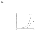
- FIG. 3 is a graph conceptually showing the correlation between the temperature of the reforming catalyst layer and the reformable flow rate rk and the combustible flow rate ck.
- the combustible flow rate ck(T) is larger than the reformable flow rate rk(T), and the value of ck(T) exceeds 0 at a lower temperature. Therefore, it is possible to start combustion at a low temperature, and finish the combustion and start reforming when rk(T) exceeds 0.
- T (t in + t out )/2)
- the combustible flow rate ck for catalytic combustion is calculated using this T (step 2-2).
- An air flow rate is calculated from the calculated ck and beforehand determined O 2/ C, and air at this flow rate is supplied to the reforming catalyst layer (step 2-3).
- the hydrocarbon-based fuel at the flow rate ck is supplied to the catalyst layer (step 2-4) to start catalytic combustion.
- the above-described step 3 is performed.
- the steps 2-1 to 2-4 and the step 3 are repeated to increase the hydrocarbon-based fuel to be catalytically combusted, and when rk calculated in the step 3 exceeds zero, the supply of the hydrocarbon-based fuel is stopped (step 2-5), and the supply of air is stopped (step 2-6) to finish the catalytic combustion. Then, the step 4 and the subsequent steps are performed, and reforming is started in the first-time step 6.
- a hydrocarbon-based fuel flow rate rk0 supplied in the first-time step 6 repeat the steps 2-1 to 2-4 to increase the hydrocarbon-based fuel to be catalytically combusted to rk0 and maintain rk0, then perform the step 3, and perform the step 4 and the subsequent steps when the calculated rk becomes rk0 or more.
- the flow rate of air supplied to the reforming catalyst layer is decreased from a flow rate required for catalytic combustion to a flow rate required for autothermal reforming to finish catalytic combustion and simultaneously start reforming.
- the above rk0 may be a certain flow rate lower than the hydrocarbon-based fuel flow rate at the completion of start-up.
- this flow rate may be a flow rate equal to or less than a hydrocarbon-based fuel flow rate at which the combustion gas flows through the fuel cell to result in a temperature at which the fuel cell is degraded.
- the steps 2-1 to 2-2 it is possible to repeat the steps 2-1 to 2-2, perform the steps 2-3 and 2-4, when the calculated ck exceeds rk0, to start catalytic combustion, repeatedly perform the step 3, and perform the step 4 and the subsequent steps when rk calculated in the step 3 becomes rk0 or more.
- the flow rate of air supplied to the reforming catalyst layer is decreased from the flow rate required for catalytic combustion to the flow rate required for autothermal reforming to finish catalytic combustion and simultaneously start reforming.
- a plurality of divided regions into which the reforming catalyst layer is segmented along the gas flow direction are considered.
- temperatures at a plurality of points which locate at different positions along the gas flow direction in the reforming catalyst layer are measured.
- flow rate(s) of the hydrocarbon-based fuel that can be reformed in one or more of the above plurality of divided regions are calculated, based on these temperatures at the plurality of points.
- the total value of the calculated flow rate(s) is determined as the flow rate of the hydrocarbon-based fuel that can be reformed in the reforming catalyst layer.
- this flow rate is the above total value.
- thermocouples S 1 to S 5 are provided at the inlet and outlet of the reforming catalyst layer, and the borders between the divided regions, respectively (S 1 to S 5 ). Temperatures measured by the thermocouples S 1 to S 5 are respectively represented as t 1 to t 5 .
- a reformable flow rate rk i (T i ) in each divided region Z i is calculated from this T i , and a value obtained by summing the reformable flow rates rk i (T i ) is determined as the reformable flow rate rk in the reforming catalyst layer.
- rk i (T i ) may be beforehand obtained by experiment.
- the fuel cell system can be started up as in embodiment 1-1, except the above.
- This fuel cell system includes:
- This control means has a fuel flow rate calculating function for calculating the flow rate of the hydrocarbon-based fuel that can be reformed in the reforming catalyst layer, based on the measured temperature of the reforming catalyst layer, and a fuel flow rate controlling function for controlling the hydrocarbon-based fuel supplied to the reforming catalyst layer to flow at the calculated flow rate.
- This control means can increase the feed rate of the hydrocarbon-based fuel to the reforming catalyst layer, while repeatedly operating the above fuel flow rate calculating function and the above fuel flow rate controlling function, until the feed rate of the hydrocarbon-based fuel to the reforming catalyst layer becomes a flow rate at the completion of start-up.
- the control means may include, for example, a computer 10, a flowmeter, and a flow rate control valve.
- a flowmeter 12a and a flow rate control valve 11 a for the hydrocarbon-based fuel may be used to control the feed rate of the hydrocarbon-based fuel to the reforming catalyst layer.
- a flow rate signal is input to the computer 10 from the flowmeter 12a, and this computer may output to the flow rate control valve 11 a an opening degree signal, which is calculated by an appropriate method, such as an PID calculation, so that the present value of the flow rate, and a reformable flow rate calculated by the computer 10 become equal.
- a mass flow controller for the hydrocarbon-based fuel may be used instead of the flowmeter 12a and the flow rate control valve 11 a, though not shown.
- the computer 10 may convert a calculated reformable flow rate to a signal and output the signal to the mass flow controller.
- pressurization means such as a pump or a blower, for the hydrocarbon-based fuel that can change the flow rate according to the input signal may be used instead of the flow rate control valve 11 a, though not shown.
- a flow rate signal is input to the computer 10 from the flowmeter 12a, and this computer may output to the pressurization means a flow rate signal, which is calculated by an appropriate method, such as an PID calculation, so that the present value of the flow rate, and a reformable flow rate calculated by the computer 10 become equal.
- the control means may control one or both of the steam flow rate and the oxygen-containing gas flow rate, as required.
- a flowmeter 12b and a flow rate control valve 11 b for water may be used for the control of the flow rate of the steam.
- a pump for water that can change the flow rate according to the input signal, or a mass flow controller for water may be used, though not shown.
- a flowmeter 11c and a flow rate control valve 12c for air may be used for the control of the flow rate of the oxygen-containing gas.
- a blower for air that can change the flow rate according to the input signal, or a mass flow controller for air may be used, though not shown.
- the flow rate of the hydrocarbon-based fuel, the steam, and the oxygen-containing gas may be controlled, with these in the state of gas, and in some cases, the flow rate may be controlled, with these in the state of liquid before being vaporized.
- control means may calculate the required flow rate of one or both of the steam and the oxygen-containing gas, as required.
- hydrocarbon-based fuel appropriately selected from compounds of which molecules contain carbon and hydrogen (may also contain other elements, such as oxygen) or mixtures thereof that are publicly known as raw materials of reformed gas in the field of SOFCs.
- compounds of which molecules contain carbon and hydrogen such as hydrocarbons and alcohols.
- hydrocarbon fuels such as methane, ethane, propane, butane, natural gas, LPG (liquefied petroleum gas), city gas, gasoline, naphtha, kerosene and gas oil, alcohols, such as methanol and ethanol, ethers, such as dimethylether, and the like may be used.
- kerosene and LPG are preferred because they are readily available. In addition, they can be stored in a stand-alone manner, and therefore, they are useful in areas where the city gas pipeline is not built. Further, an SOFC power generating equipment using kerosene or LPG is useful as an emergency power supply. Particularly, kerosene is preferred because it is easy to handle.
- the present invention may be suitably applied to a system equipped with a high temperature fuel cell that requires the prevention of the oxidative degradation of the anode.
- a metal electrode is used for the anode
- the oxidative degradation of the anode may occur, for example, at about 400°C.
- Such a fuel cell includes an SOFC and an MCFC.
- the SOFC may be appropriately selected for use from publicly known SOFCs having various shapes, such as planar and tubular SOFCs.
- SOFC generally, an oxygen-ion conductive ceramic or a proton-ion conductive ceramic is used as the electrolyte.
- the MCFC may also be appropriately selected for use from publicly known MCFCs.
- the SOFC or the MCFC may be a single cell, but practically, a stack in which a plurality of single cells are arrayed (the stack is sometimes referred to as a bundle in the case of a tubular type, and the stack in this specification includes a bundle) is preferably used. In this case, one stack or a plurality of stacks may be used.
- a reformer produces a reformed gas containing hydrogen from a hydrocarbon-based fuel.
- any of steam reforming, partial oxidation reforming and autothermal reforming in which a steam reforming reaction is accompanied by a partial oxidation reaction may be performed.
- a steam reforming catalyst having steam reforming activity a partial oxidation reforming catalyst having partial oxidation reforming activity, or an autothermal reforming catalyst having both partial oxidation reforming activity and steam reforming activity may be appropriately used.
- a hydrocarbon-based fuel (vaporized beforehand as required) and steam, and further an oxygen-containing gas, such as air, as required, may be supplied to the reformer (the reforming catalyst layer), each independently, or appropriately mixed beforehand.
- the reformed gas is supplied to the anode of the high temperature fuel cell.
- an indirect internal reforming SOFC is excellent in that the thermal efficiency of the system can be increased.
- the indirect internal reforming SOFC has a reformer for producing a reformed gas containing hydrogen from a hydrocarbon-based fuel using a steam reforming reaction and an SOFC.
- a steam reforming reaction may be performed, and autothermal reforming in which a steam reforming reaction is accompanied by a partial oxidation reaction may be performed.
- no partial oxidation reaction occurs after the completion of start-up.
- the autothermal reforming is designed so that steam reforming is predominant after the completion of start-up, and therefore, the reforming reaction is an overall endothermic reaction.
- Heat required for the reforming reaction is supplied from the SOFC.
- the reformer and the SOFC are housed in one module container and modularized.
- the reformer is disposed at a position where it receives thermal radiation from the SOFC.
- the reformer is heated by thermal radiation from the SOFC during electric power generation.
- the SOFC may be heated by combusting the anode off-gas, which is discharged from the SOFC, at the cell outlet.
- the reformer is preferably disposed at a position where radiation heat can be directly transferred from the SOFC to the outer surface of the reformer. Therefore, it is preferred that there is substantially no obstacle between the reformer and the SOFC, that is, it is preferred to make the region between the reformer and the SOFC be an empty space. Also, the distance between the reformer and the SOFC is preferably as short as possible.
- Each supply gas is supplied to the reformer or the SOFC, after being appropriately preheated as required.
- the module container may be any appropriate container capable of housing the SOFC and the reformer.
- An appropriate material having resistance to the environment used for example, stainless steel, may be used as the material of the container.
- a connection port is appropriately provided for the container for gas interfacing or the like.
- the module container is preferably hermetic in order to prevent communication between the interior of the module container and the surroundings (atmosphere).
- a publicly known catalyst may be used for each of the steam reforming catalyst, the partial oxidation reforming catalyst and the autothermal reforming catalyst used in the reformer.
- the partial oxidation reforming catalyst include a platinum-based catalyst.
- the steam reforming catalyst include ruthenium-based and nickel-based catalysts.
- the autothermal reforming catalyst include a rhodium-based catalyst.
- the reforming catalyst that can promote combustion include platinum-based and rhodium-based catalysts.
- a temperature at which the partial oxidation reforming reaction can proceed is, for example, 200°C or more.
- the temperature at which the steam reforming reaction can proceed is, for example, 400°C or more.
- steam is added to a reforming raw material, such as kerosene.
- the reaction temperature of the steam reforming may be in the range of, for example, 400°C to 1000°C, preferably 500°C to 850°C, and further preferably 550°C to 800°C.
- An amount of the steam introduced into the reaction system is defined as a ratio of the number of moles of water molecules to the number of moles of carbon atoms contained in the hydrocarbon-based fuel (steam/carbon ratio). This value is preferably 1 to 10, more preferably 1.5 to 7, and further preferably 2 to 5.
- a space velocity (LHSV) can be represented as A/B, wherein a flow velocity of the hydrocarbon-based fuel in a liquid state is represented as A (L/h), and a volume of the catalyst layer is represented as B (L).
- This value is set in the range of preferably 0.05 to 20 h -1 , more preferably 0.1 to 10 h -1 , and further preferably 0.2 to 5 h -1 .
- an oxygen-containing gas is added to the reforming raw material.
- the oxygen-containing gas may be pure oxygen, but in terms of the ease of availability, air is preferred.
- the oxygen-containing gas may be added so that the endothermic reaction accompanying the steam reforming reaction is balanced, and an amount of heat generation such that the temperature of the reforming catalyst layer and the SOFC can be maintained or increased is obtained.
- a ratio of the number of moles of oxygen molecules to the number of moles of carbon atoms contained in the hydrocarbon-based fuel is preferably 0.005 to 1, more preferably 0.01 to 0.75, and further preferably 0.02 to 0.6.
- a reaction temperature of the autothermal reforming reaction is set in the range of, for example, 400°C to 1000°C, preferably 450°C to 850°C, and further preferably 500°C to 800°C.
- the space velocity (LHSV) is selected in the range of preferably 0.05 to 20 h -1 , more preferably 0.1 to 10 h -1 , and further preferably 0.2 to 5 h -1 .
- the steam/carbon ratio is preferably 1 to 10, more preferably 1.5 to 7, and further preferably 2 to 5.
- an oxygen-containing gas is added to the reforming raw material.
- the oxygen-containing gas may be pure oxygen, but in terms of the ease of availability, air is preferred.
- An amount of the oxygen-containing gas added is appropriately determined in terms of heat loss and the like to ensure a temperature at which the reaction proceeds. With respect to this amount, the ratio of the number of moles of oxygen molecules to the number of moles of carbon atoms contained in the hydrocarbon-based fuel (oxygen/carbon ratio) is preferably 0.1 to 3 and more preferably 0.2 to 0.7.
- a reaction temperature of the partial oxidation reaction may be set in the range of, for example, 450°C to 1000°C, preferably 500°C to 850°C, and further preferably 550°C to 800°C.
- a space velocity (LHSV) is selected in the range of preferably 0.1 to 30 h -1 .
- Steam can be introduced into the reaction system to suppress the generation of soot, and with respect to an amount of the steam, the steam/carbon ratio is preferably 0.1 to 5, more preferably 0.1 to 3, and further preferably 1 to 2.
- publicly known components of a high temperature fuel cell system may be appropriately provided as required.
- the publicly known components include a desulfurizer for reducing a sulfur content of a hydrocarbon-based fuel; a vaporizer for vaporizing a liquid; pressure increasing means for pressurizing various fluids, such as a pump, a compressor, and a blower; flow rate controlling means or flow path blocking/switching means for controlling the flow rate of a fluid, or blocking/switching the flow of a fluid, such as a valve; a heat exchanger for performing heat exchange and heat recovery; a condenser for condensing a gas; heating/warming means for eternally heating various equipment with steam or the like; storage means of a hydrocarbon-based fuel and combustibles; an air or electrical system for instrumentation; a signal system for control; a control device; and an electrical system for output and powering; and the like.
- the present invention can be applied to a high temperature fuel cell system used for, for example, a stationary or mobile electric power generation system and a cogeneration system.
Landscapes
- Chemical & Material Sciences (AREA)
- Chemical Kinetics & Catalysis (AREA)
- Engineering & Computer Science (AREA)
- General Chemical & Material Sciences (AREA)
- Sustainable Energy (AREA)
- Sustainable Development (AREA)
- Manufacturing & Machinery (AREA)
- Electrochemistry (AREA)
- Life Sciences & Earth Sciences (AREA)
- Organic Chemistry (AREA)
- Combustion & Propulsion (AREA)
- Health & Medical Sciences (AREA)
- General Health & Medical Sciences (AREA)
- Inorganic Chemistry (AREA)
- Fuel Cell (AREA)
- Hydrogen, Water And Hydrids (AREA)
Applications Claiming Priority (2)
| Application Number | Priority Date | Filing Date | Title |
|---|---|---|---|
| JP2007222464A JP5325403B2 (ja) | 2007-08-29 | 2007-08-29 | 燃料電池システムの起動方法 |
| PCT/JP2008/064430 WO2009028327A1 (ja) | 2007-08-29 | 2008-08-11 | 燃料電池システムとその起動方法 |
Publications (2)
| Publication Number | Publication Date |
|---|---|
| EP2199255A1 true EP2199255A1 (de) | 2010-06-23 |
| EP2199255A4 EP2199255A4 (de) | 2013-09-11 |
Family
ID=40387053
Family Applications (1)
| Application Number | Title | Priority Date | Filing Date |
|---|---|---|---|
| EP08828710.7A Withdrawn EP2199255A4 (de) | 2007-08-29 | 2008-08-11 | Brennstoffzellensystem und verfahren zum anfahren des brennstoffzellensystems |
Country Status (8)
| Country | Link |
|---|---|
| US (2) | US8574775B2 (de) |
| EP (1) | EP2199255A4 (de) |
| JP (1) | JP5325403B2 (de) |
| KR (1) | KR20100063720A (de) |
| CN (1) | CN101808935B (de) |
| CA (1) | CA2697652A1 (de) |
| TW (1) | TWI447996B (de) |
| WO (1) | WO2009028327A1 (de) |
Cited By (5)
| Publication number | Priority date | Publication date | Assignee | Title |
|---|---|---|---|---|
| EP2256848A1 (de) * | 2009-05-28 | 2010-12-01 | Toto Ltd. | Festoxid-Brennstoffzellenvorrichtung |
| EP2256849A1 (de) * | 2009-05-28 | 2010-12-01 | Toto Ltd. | Festoxid-Brennstoffzellenvorrichtung |
| US20130196239A1 (en) * | 2010-09-30 | 2013-08-01 | Toto Ltd. | Solid oxide fuel cell device |
| EP2645462A1 (de) * | 2012-03-27 | 2013-10-02 | Toto Ltd. | Festoxidbrennstoffzellensystem |
| WO2020102837A1 (de) * | 2018-11-19 | 2020-05-28 | Avl List Gmbh | Verfahren zum aufheizen eines brennstoffzellensystems sowie brennstoffzellensystem |
Families Citing this family (18)
| Publication number | Priority date | Publication date | Assignee | Title |
|---|---|---|---|---|
| JP5307592B2 (ja) * | 2009-03-19 | 2013-10-02 | Jx日鉱日石エネルギー株式会社 | 間接内部改質型固体酸化物形燃料電池システムの運転方法 |
| US9219283B2 (en) | 2009-04-24 | 2015-12-22 | Kyocera Corporation | Method for controlling fuel cell device during power generation start by controlling power conditioner |
| JP5401170B2 (ja) * | 2009-05-21 | 2014-01-29 | アイシン精機株式会社 | 燃料電池システム |
| JP4748465B2 (ja) * | 2009-05-28 | 2011-08-17 | Toto株式会社 | 燃料電池装置 |
| JP4761259B2 (ja) | 2009-05-28 | 2011-08-31 | Toto株式会社 | 固体電解質型燃料電池 |
| JP5500504B2 (ja) | 2009-05-28 | 2014-05-21 | Toto株式会社 | 固体電解質型燃料電池 |
| JP4707023B2 (ja) * | 2009-09-30 | 2011-06-22 | Toto株式会社 | 固体電解質型燃料電池 |
| EP2402964B1 (de) | 2010-07-02 | 2018-12-26 | Solum Co., Ltd. | Transformator und diesen enthaltender Flachbildschirm |
| JP5388140B2 (ja) | 2010-07-02 | 2014-01-15 | サムソン エレクトロ−メカニックス カンパニーリミテッド. | トランスフォーマ及びこれを備えた平板ディスプレイ装置 |
| JP5765667B2 (ja) * | 2011-04-11 | 2015-08-19 | Toto株式会社 | 固体酸化物形燃料電池装置 |
| JP5765029B2 (ja) * | 2011-04-11 | 2015-08-19 | Toto株式会社 | 固体酸化物形燃料電池装置 |
| JP6380732B2 (ja) * | 2014-03-20 | 2018-08-29 | Toto株式会社 | 固体酸化物型燃料電池装置 |
| CN106910912B (zh) | 2015-12-18 | 2020-06-30 | 通用电气公司 | 燃料电池系统及其操作方法及燃料电池发电厂 |
| US10622650B2 (en) | 2017-11-13 | 2020-04-14 | Lg Fuel Cell Systems Inc. | System and method for fuel cell stack temperature control |
| US10763526B2 (en) | 2017-11-13 | 2020-09-01 | Lg Electronics, Inc. | System and method for fuel cell stack temperature control |
| CN112136238B (zh) * | 2018-06-01 | 2024-02-27 | 日产自动车株式会社 | 催化燃烧装置的控制方法和催化燃烧系统 |
| CN112687918B (zh) * | 2020-12-17 | 2022-04-26 | 潍柴动力股份有限公司 | 固体氧化物燃料电池系统及其控制方法 |
| CN114988363A (zh) * | 2022-07-25 | 2022-09-02 | 广东佛燃科技有限公司 | 一种用于固体氧化物燃料电池系统的重整器设计及其运行方法 |
Family Cites Families (15)
| Publication number | Priority date | Publication date | Assignee | Title |
|---|---|---|---|---|
| JP2840000B2 (ja) | 1993-02-04 | 1998-12-24 | 溶融炭酸塩型燃料電池発電システム技術研究組合 | 燃料電池システムとその制御方法 |
| JP4590730B2 (ja) * | 2000-12-27 | 2010-12-01 | トヨタ自動車株式会社 | 改質器の起動制御 |
| DE10213134A1 (de) * | 2002-03-23 | 2003-10-09 | Daimler Chrysler Ag | Brennstoffzelle und Verfahren zum Kaltstarten einer solchen Brennstoffzelle |
| TW558852B (en) * | 2002-07-12 | 2003-10-21 | Asia Pacific Fuel Cell Tech | Control apparatus and method of fuel cell set |
| JP2004075403A (ja) * | 2002-08-09 | 2004-03-11 | Honda Motor Co Ltd | 水素発生装置 |
| JP4369685B2 (ja) * | 2003-02-25 | 2009-11-25 | 京セラ株式会社 | 燃料電池の運転方法 |
| US8277524B2 (en) * | 2004-03-16 | 2012-10-02 | Delphi Technologies, Inc. | Reformer start-up strategy for use in a solid oxide fuel cell control system |
| JP2006004868A (ja) * | 2004-06-21 | 2006-01-05 | Sony Corp | 燃料電池システム及び燃料電池起動方法 |
| TWI234309B (en) * | 2004-06-28 | 2005-06-11 | Asia Pacific Fuel Cell Tech | Transient start and temperature adjustment apparatus of humidifying module for fuel cell |
| JP4767543B2 (ja) * | 2005-01-07 | 2011-09-07 | Jx日鉱日石エネルギー株式会社 | 固体酸化物形燃料電池システムの起動方法 |
| TWI257191B (en) * | 2005-08-19 | 2006-06-21 | Tatung Co | Fuel cell system |
| JP2007073302A (ja) | 2005-09-06 | 2007-03-22 | Nissan Motor Co Ltd | 燃料改質システム |
| TWI305433B (en) * | 2005-12-13 | 2009-01-11 | Chung Shan Inst Of Science | Control device and method for portable air-cooled fuel cell system |
| JP4887048B2 (ja) * | 2006-01-30 | 2012-02-29 | アイシン精機株式会社 | 燃料電池の起動方法及び燃料電池システム |
| JP5164441B2 (ja) * | 2007-06-13 | 2013-03-21 | Jx日鉱日石エネルギー株式会社 | 燃料電池システムの起動方法 |
-
2007
- 2007-08-29 JP JP2007222464A patent/JP5325403B2/ja not_active Expired - Fee Related
-
2008
- 2008-08-11 CA CA2697652A patent/CA2697652A1/en not_active Abandoned
- 2008-08-11 WO PCT/JP2008/064430 patent/WO2009028327A1/ja not_active Ceased
- 2008-08-11 US US12/675,161 patent/US8574775B2/en not_active Expired - Fee Related
- 2008-08-11 KR KR1020107005864A patent/KR20100063720A/ko not_active Ceased
- 2008-08-11 EP EP08828710.7A patent/EP2199255A4/de not_active Withdrawn
- 2008-08-11 CN CN2008801042894A patent/CN101808935B/zh not_active Expired - Fee Related
- 2008-08-19 TW TW097131580A patent/TWI447996B/zh not_active IP Right Cessation
-
2013
- 2013-10-03 US US14/045,491 patent/US20140106250A1/en not_active Abandoned
Cited By (10)
| Publication number | Priority date | Publication date | Assignee | Title |
|---|---|---|---|---|
| EP2256848A1 (de) * | 2009-05-28 | 2010-12-01 | Toto Ltd. | Festoxid-Brennstoffzellenvorrichtung |
| EP2256849A1 (de) * | 2009-05-28 | 2010-12-01 | Toto Ltd. | Festoxid-Brennstoffzellenvorrichtung |
| US8974978B2 (en) | 2009-05-28 | 2015-03-10 | Toto Ltd. | Solid oxide fuel cell device |
| US20130196239A1 (en) * | 2010-09-30 | 2013-08-01 | Toto Ltd. | Solid oxide fuel cell device |
| US9209469B2 (en) * | 2010-09-30 | 2015-12-08 | Toto Ltd. | Solid oxide fuel cell device |
| EP2645462A1 (de) * | 2012-03-27 | 2013-10-02 | Toto Ltd. | Festoxidbrennstoffzellensystem |
| WO2020102837A1 (de) * | 2018-11-19 | 2020-05-28 | Avl List Gmbh | Verfahren zum aufheizen eines brennstoffzellensystems sowie brennstoffzellensystem |
| AT521901A1 (de) * | 2018-11-19 | 2020-06-15 | Avl List Gmbh | Verfahren zum Aufheizen eines Brennstoffzellensystems sowie Brennstoffzellensystem |
| AT521901B1 (de) * | 2018-11-19 | 2020-10-15 | Avl List Gmbh | Verfahren zum Aufheizen eines Brennstoffzellensystems sowie Brennstoffzellensystem |
| US12218390B2 (en) | 2018-11-19 | 2025-02-04 | Avl List Gmbh | Method for heating a fuel cell system and fuel cell system |
Also Published As
| Publication number | Publication date |
|---|---|
| EP2199255A4 (de) | 2013-09-11 |
| WO2009028327A1 (ja) | 2009-03-05 |
| JP2009051712A (ja) | 2009-03-12 |
| US8574775B2 (en) | 2013-11-05 |
| TWI447996B (zh) | 2014-08-01 |
| CN101808935B (zh) | 2012-10-10 |
| US20140106250A1 (en) | 2014-04-17 |
| US20100310951A1 (en) | 2010-12-09 |
| CN101808935A (zh) | 2010-08-18 |
| TW200929670A (en) | 2009-07-01 |
| CA2697652A1 (en) | 2009-03-05 |
| KR20100063720A (ko) | 2010-06-11 |
| JP5325403B2 (ja) | 2013-10-23 |
Similar Documents
| Publication | Publication Date | Title |
|---|---|---|
| US8574775B2 (en) | Fuel cell system and method for starting up the same | |
| EP2233431A1 (de) | Brennstoffzellensystem und verfahren zum anfahren davon | |
| EP2173000A1 (de) | Brennstoffbatteriesystem und sein aktivierungsverfahren | |
| EP2246926B1 (de) | Festoxid-brennstoffzelle mit indirekter interner reformierung und verfahren zum stoppen | |
| EP2278650B1 (de) | Verfahren für den betrieb eines festoxidbrennstoffzellensystems mit indirektem internem reformer | |
| US8771888B2 (en) | Fuel cell system and method of load following operation of the same | |
| JP5078698B2 (ja) | 燃料電池システムの負荷追従運転方法 | |
| EP2267827A1 (de) | Brennstoffzellensystem und verfahren zum lastfolgebetrieb dieses systems | |
| EP2418721A1 (de) | Verfahren zum stoppen der indirekten internen reformierung einer festoxidbrennstoffzelle | |
| JP5078697B2 (ja) | 燃料電池システムの負荷追従運転方法 | |
| US8790837B2 (en) | Method for shutting down indirect internal reforming solid oxide fuel cell | |
| US8865358B2 (en) | Method for load following operation of fuel cell system |
Legal Events
| Date | Code | Title | Description |
|---|---|---|---|
| PUAI | Public reference made under article 153(3) epc to a published international application that has entered the european phase |
Free format text: ORIGINAL CODE: 0009012 |
|
| 17P | Request for examination filed |
Effective date: 20100329 |
|
| AK | Designated contracting states |
Kind code of ref document: A1 Designated state(s): AT BE BG CH CY CZ DE DK EE ES FI FR GB GR HR HU IE IS IT LI LT LU LV MC MT NL NO PL PT RO SE SI SK TR |
|
| AX | Request for extension of the european patent |
Extension state: AL BA MK RS |
|
| DAX | Request for extension of the european patent (deleted) | ||
| A4 | Supplementary search report drawn up and despatched |
Effective date: 20130813 |
|
| RIC1 | Information provided on ipc code assigned before grant |
Ipc: C01B 3/38 20060101AFI20130807BHEP Ipc: H01M 8/12 20060101ALI20130807BHEP Ipc: H01M 8/06 20060101ALI20130807BHEP Ipc: H01M 8/04 20060101ALI20130807BHEP |
|
| STAA | Information on the status of an ep patent application or granted ep patent |
Free format text: STATUS: THE APPLICATION IS DEEMED TO BE WITHDRAWN |
|
| 18D | Application deemed to be withdrawn |
Effective date: 20160301 |