EP2199312B1 - Film de structure séparé en microphases, procédé de fabrication du film de structure séparé en microphases et pile à combustible - Google Patents
Film de structure séparé en microphases, procédé de fabrication du film de structure séparé en microphases et pile à combustible Download PDFInfo
- Publication number
- EP2199312B1 EP2199312B1 EP08828950.9A EP08828950A EP2199312B1 EP 2199312 B1 EP2199312 B1 EP 2199312B1 EP 08828950 A EP08828950 A EP 08828950A EP 2199312 B1 EP2199312 B1 EP 2199312B1
- Authority
- EP
- European Patent Office
- Prior art keywords
- integer
- microphase
- polymer component
- separated structure
- group
- Prior art date
- Legal status (The legal status is an assumption and is not a legal conclusion. Google has not performed a legal analysis and makes no representation as to the accuracy of the status listed.)
- Not-in-force
Links
- 238000000034 method Methods 0.000 title claims description 42
- 239000000446 fuel Substances 0.000 title claims description 19
- 230000008569 process Effects 0.000 title description 2
- -1 poly(acrylate) Polymers 0.000 claims description 108
- 239000012528 membrane Substances 0.000 claims description 104
- 229920001400 block copolymer Polymers 0.000 claims description 88
- 229920001477 hydrophilic polymer Polymers 0.000 claims description 54
- 229920001600 hydrophobic polymer Polymers 0.000 claims description 45
- 125000000217 alkyl group Chemical group 0.000 claims description 44
- 125000004435 hydrogen atom Chemical group [H]* 0.000 claims description 41
- 239000000758 substrate Substances 0.000 claims description 41
- 239000002904 solvent Substances 0.000 claims description 38
- 238000004519 manufacturing process Methods 0.000 claims description 28
- 238000005530 etching Methods 0.000 claims description 24
- 125000004432 carbon atom Chemical group C* 0.000 claims description 21
- 239000011148 porous material Substances 0.000 claims description 19
- AZQWKYJCGOJGHM-UHFFFAOYSA-N 1,4-benzoquinone Chemical compound O=C1C=CC(=O)C=C1 AZQWKYJCGOJGHM-UHFFFAOYSA-N 0.000 claims description 18
- 150000004945 aromatic hydrocarbons Chemical class 0.000 claims description 18
- 229910052739 hydrogen Inorganic materials 0.000 claims description 18
- 239000001257 hydrogen Substances 0.000 claims description 18
- 238000010438 heat treatment Methods 0.000 claims description 16
- 239000011159 matrix material Substances 0.000 claims description 16
- 229920000642 polymer Polymers 0.000 claims description 16
- 229920003171 Poly (ethylene oxide) Polymers 0.000 claims description 13
- 238000009826 distribution Methods 0.000 claims description 13
- 229920000058 polyacrylate Polymers 0.000 claims description 13
- 239000005518 polymer electrolyte Substances 0.000 claims description 13
- 229920000193 polymethacrylate Polymers 0.000 claims description 13
- 229920001577 copolymer Polymers 0.000 claims description 12
- 230000002209 hydrophobic effect Effects 0.000 claims description 10
- 229910052723 transition metal Inorganic materials 0.000 claims description 10
- 150000003624 transition metals Chemical class 0.000 claims description 10
- 125000003118 aryl group Chemical group 0.000 claims description 9
- 125000004093 cyano group Chemical group *C#N 0.000 claims description 9
- 150000004032 porphyrins Chemical group 0.000 claims description 9
- XMWRBQBLMFGWIX-UHFFFAOYSA-N C60 fullerene Chemical compound C12=C3C(C4=C56)=C7C8=C5C5=C9C%10=C6C6=C4C1=C1C4=C6C6=C%10C%10=C9C9=C%11C5=C8C5=C8C7=C3C3=C7C2=C1C1=C2C4=C6C4=C%10C6=C9C9=C%11C5=C5C8=C3C3=C7C1=C1C2=C4C6=C2C9=C5C3=C12 XMWRBQBLMFGWIX-UHFFFAOYSA-N 0.000 claims description 8
- 238000001704 evaporation Methods 0.000 claims description 8
- 229910003472 fullerene Inorganic materials 0.000 claims description 8
- 125000000623 heterocyclic group Chemical group 0.000 claims description 8
- 239000007788 liquid Substances 0.000 claims description 8
- 125000000951 phenoxy group Chemical group [H]C1=C([H])C([H])=C(O*)C([H])=C1[H] 0.000 claims description 8
- 229910052736 halogen Inorganic materials 0.000 claims description 7
- 150000002367 halogens Chemical class 0.000 claims description 7
- 229910021645 metal ion Inorganic materials 0.000 claims description 7
- 125000001424 substituent group Chemical group 0.000 claims description 7
- 238000000354 decomposition reaction Methods 0.000 claims description 5
- OKTJSMMVPCPJKN-UHFFFAOYSA-N Carbon Chemical compound [C] OKTJSMMVPCPJKN-UHFFFAOYSA-N 0.000 claims description 4
- 229910052799 carbon Inorganic materials 0.000 claims description 3
- 238000002844 melting Methods 0.000 claims description 3
- 230000008018 melting Effects 0.000 claims description 3
- 125000003262 carboxylic acid ester group Chemical group [H]C([H])([*:2])OC(=O)C([H])([H])[*:1] 0.000 claims 5
- 0 CC(C)(*)c1ccc(B2OCC(CCCC*)CO2)cc1 Chemical compound CC(C)(*)c1ccc(B2OCC(CCCC*)CO2)cc1 0.000 description 37
- 239000000243 solution Substances 0.000 description 31
- HEDRZPFGACZZDS-UHFFFAOYSA-N Chloroform Chemical compound ClC(Cl)Cl HEDRZPFGACZZDS-UHFFFAOYSA-N 0.000 description 30
- 238000006243 chemical reaction Methods 0.000 description 25
- 238000003756 stirring Methods 0.000 description 20
- 239000000463 material Substances 0.000 description 16
- 238000006116 polymerization reaction Methods 0.000 description 16
- XXSPGBOGLXKMDU-UHFFFAOYSA-M 2-bromo-2-methylpropanoate Chemical compound CC(C)(Br)C([O-])=O XXSPGBOGLXKMDU-UHFFFAOYSA-M 0.000 description 13
- ZMANZCXQSJIPKH-UHFFFAOYSA-N Triethylamine Chemical compound CCN(CC)CC ZMANZCXQSJIPKH-UHFFFAOYSA-N 0.000 description 12
- XLYOFNOQVPJJNP-UHFFFAOYSA-N water Substances O XLYOFNOQVPJJNP-UHFFFAOYSA-N 0.000 description 12
- YMWUJEATGCHHMB-UHFFFAOYSA-N Dichloromethane Chemical compound ClCCl YMWUJEATGCHHMB-UHFFFAOYSA-N 0.000 description 11
- 238000010560 atom transfer radical polymerization reaction Methods 0.000 description 11
- 239000003999 initiator Substances 0.000 description 11
- OKKJLVBELUTLKV-UHFFFAOYSA-N Methanol Chemical compound OC OKKJLVBELUTLKV-UHFFFAOYSA-N 0.000 description 9
- YXFVVABEGXRONW-UHFFFAOYSA-N Toluene Chemical compound CC1=CC=CC=C1 YXFVVABEGXRONW-UHFFFAOYSA-N 0.000 description 9
- 230000005684 electric field Effects 0.000 description 9
- RAXXELZNTBOGNW-UHFFFAOYSA-N imidazole Natural products C1=CNC=N1 RAXXELZNTBOGNW-UHFFFAOYSA-N 0.000 description 9
- 229920002223 polystyrene Polymers 0.000 description 9
- WYURNTSHIVDZCO-UHFFFAOYSA-N Tetrahydrofuran Chemical compound C1CCOC1 WYURNTSHIVDZCO-UHFFFAOYSA-N 0.000 description 8
- 239000007787 solid Substances 0.000 description 8
- 230000005540 biological transmission Effects 0.000 description 7
- 230000015572 biosynthetic process Effects 0.000 description 7
- 239000004020 conductor Substances 0.000 description 7
- 238000003786 synthesis reaction Methods 0.000 description 7
- QTBSBXVTEAMEQO-UHFFFAOYSA-N Acetic acid Chemical compound CC(O)=O QTBSBXVTEAMEQO-UHFFFAOYSA-N 0.000 description 6
- CSNNHWWHGAXBCP-UHFFFAOYSA-L Magnesium sulfate Chemical compound [Mg+2].[O-][S+2]([O-])([O-])[O-] CSNNHWWHGAXBCP-UHFFFAOYSA-L 0.000 description 6
- ZMXDDKWLCZADIW-UHFFFAOYSA-N N,N-Dimethylformamide Chemical compound CN(C)C=O ZMXDDKWLCZADIW-UHFFFAOYSA-N 0.000 description 6
- XUIMIQQOPSSXEZ-UHFFFAOYSA-N Silicon Chemical compound [Si] XUIMIQQOPSSXEZ-UHFFFAOYSA-N 0.000 description 6
- RDOXTESZEPMUJZ-UHFFFAOYSA-N anisole Chemical compound COC1=CC=CC=C1 RDOXTESZEPMUJZ-UHFFFAOYSA-N 0.000 description 6
- 239000003054 catalyst Substances 0.000 description 6
- 239000003792 electrolyte Substances 0.000 description 6
- 238000010828 elution Methods 0.000 description 6
- 239000000178 monomer Substances 0.000 description 6
- 229910052710 silicon Inorganic materials 0.000 description 6
- 239000010703 silicon Substances 0.000 description 6
- VYPSYNLAJGMNEJ-UHFFFAOYSA-N silicon dioxide Inorganic materials O=[Si]=O VYPSYNLAJGMNEJ-UHFFFAOYSA-N 0.000 description 6
- DDGNGFVNTZJMMZ-UHFFFAOYSA-N tert-butyl n-(5-hydroxypentyl)carbamate Chemical compound CC(C)(C)OC(=O)NCCCCCO DDGNGFVNTZJMMZ-UHFFFAOYSA-N 0.000 description 6
- ROFVEXUMMXZLPA-UHFFFAOYSA-N Bipyridyl Chemical compound N1=CC=CC=C1C1=CC=CC=N1 ROFVEXUMMXZLPA-UHFFFAOYSA-N 0.000 description 5
- KFZMGEQAYNKOFK-UHFFFAOYSA-N Isopropanol Chemical compound CC(C)O KFZMGEQAYNKOFK-UHFFFAOYSA-N 0.000 description 5
- 239000004793 Polystyrene Substances 0.000 description 5
- 239000010410 layer Substances 0.000 description 5
- UIIMBOGNXHQVGW-UHFFFAOYSA-M Sodium bicarbonate Chemical compound [Na+].OC([O-])=O UIIMBOGNXHQVGW-UHFFFAOYSA-M 0.000 description 4
- 229910021536 Zeolite Inorganic materials 0.000 description 4
- 150000008065 acid anhydrides Chemical class 0.000 description 4
- 150000001733 carboxylic acid esters Chemical group 0.000 description 4
- HNPSIPDUKPIQMN-UHFFFAOYSA-N dioxosilane;oxo(oxoalumanyloxy)alumane Chemical compound O=[Si]=O.O=[Al]O[Al]=O HNPSIPDUKPIQMN-UHFFFAOYSA-N 0.000 description 4
- 238000001312 dry etching Methods 0.000 description 4
- 239000010408 film Substances 0.000 description 4
- 238000005342 ion exchange Methods 0.000 description 4
- 229910052751 metal Inorganic materials 0.000 description 4
- 239000002184 metal Substances 0.000 description 4
- XTAZYLNFDRKIHJ-UHFFFAOYSA-N n,n-dioctyloctan-1-amine Chemical compound CCCCCCCCN(CCCCCCCC)CCCCCCCC XTAZYLNFDRKIHJ-UHFFFAOYSA-N 0.000 description 4
- 239000002861 polymer material Substances 0.000 description 4
- BWHMMNNQKKPAPP-UHFFFAOYSA-L potassium carbonate Chemical compound [K+].[K+].[O-]C([O-])=O BWHMMNNQKKPAPP-UHFFFAOYSA-L 0.000 description 4
- 239000000047 product Substances 0.000 description 4
- 229920005989 resin Polymers 0.000 description 4
- 239000011347 resin Substances 0.000 description 4
- 239000000741 silica gel Substances 0.000 description 4
- 229910002027 silica gel Inorganic materials 0.000 description 4
- HPALAKNZSZLMCH-UHFFFAOYSA-M sodium;chloride;hydrate Chemical class O.[Na+].[Cl-] HPALAKNZSZLMCH-UHFFFAOYSA-M 0.000 description 4
- 229920002554 vinyl polymer Polymers 0.000 description 4
- 239000010457 zeolite Substances 0.000 description 4
- OZNYBWZLXMPDRK-UHFFFAOYSA-N 1,7-dibromoperylene-3,4,9,10-tetracarboxylic acid Chemical compound C=12C3=C(Br)C=C(C(O)=O)C2=C(C(O)=O)C=CC=1C1=C(Br)C=C(C(O)=O)C2=C1C3=CC=C2C(=O)O OZNYBWZLXMPDRK-UHFFFAOYSA-N 0.000 description 3
- UHOVQNZJYSORNB-UHFFFAOYSA-N Benzene Chemical compound C1=CC=CC=C1 UHOVQNZJYSORNB-UHFFFAOYSA-N 0.000 description 3
- XEKOWRVHYACXOJ-UHFFFAOYSA-N Ethyl acetate Chemical compound CCOC(C)=O XEKOWRVHYACXOJ-UHFFFAOYSA-N 0.000 description 3
- KWYHDKDOAIKMQN-UHFFFAOYSA-N N,N,N',N'-tetramethylethylenediamine Chemical compound CN(C)CCN(C)C KWYHDKDOAIKMQN-UHFFFAOYSA-N 0.000 description 3
- 229920002845 Poly(methacrylic acid) Polymers 0.000 description 3
- 229920002125 Sokalan® Polymers 0.000 description 3
- 239000012300 argon atmosphere Substances 0.000 description 3
- 239000011248 coating agent Substances 0.000 description 3
- 238000000576 coating method Methods 0.000 description 3
- 150000001875 compounds Chemical class 0.000 description 3
- 230000001276 controlling effect Effects 0.000 description 3
- 239000010949 copper Substances 0.000 description 3
- 238000009792 diffusion process Methods 0.000 description 3
- 150000002148 esters Chemical class 0.000 description 3
- 238000001914 filtration Methods 0.000 description 3
- 229920001002 functional polymer Polymers 0.000 description 3
- 238000005227 gel permeation chromatography Methods 0.000 description 3
- 239000011521 glass Substances 0.000 description 3
- 150000002500 ions Chemical class 0.000 description 3
- 229910052943 magnesium sulfate Inorganic materials 0.000 description 3
- 235000019341 magnesium sulphate Nutrition 0.000 description 3
- UZKWTJUDCOPSNM-UHFFFAOYSA-N methoxybenzene Substances CCCCOC=C UZKWTJUDCOPSNM-UHFFFAOYSA-N 0.000 description 3
- 239000000203 mixture Substances 0.000 description 3
- VLKZOEOYAKHREP-UHFFFAOYSA-N n-Hexane Chemical compound CCCCCC VLKZOEOYAKHREP-UHFFFAOYSA-N 0.000 description 3
- 239000012044 organic layer Substances 0.000 description 3
- FVDOBFPYBSDRKH-UHFFFAOYSA-N perylene-3,4,9,10-tetracarboxylic acid Chemical compound C=12C3=CC=C(C(O)=O)C2=C(C(O)=O)C=CC=1C1=CC=C(C(O)=O)C2=C1C3=CC=C2C(=O)O FVDOBFPYBSDRKH-UHFFFAOYSA-N 0.000 description 3
- 229920002401 polyacrylamide Polymers 0.000 description 3
- 229920001451 polypropylene glycol Polymers 0.000 description 3
- 229920002451 polyvinyl alcohol Polymers 0.000 description 3
- 230000009467 reduction Effects 0.000 description 3
- 239000004449 solid propellant Substances 0.000 description 3
- 238000004528 spin coating Methods 0.000 description 3
- 239000000126 substance Substances 0.000 description 3
- YLQBMQCUIZJEEH-UHFFFAOYSA-N tetrahydrofuran Natural products C=1C=COC=1 YLQBMQCUIZJEEH-UHFFFAOYSA-N 0.000 description 3
- 238000005406 washing Methods 0.000 description 3
- MZNURMGGTHSOOH-UHFFFAOYSA-N (2-bromo-4,7-dimethyl-3-oxo-7-bicyclo[2.2.1]heptanyl)methanesulfonyl chloride Chemical compound C1CC2(C)C(=O)C(Br)C1C2(CS(Cl)(=O)=O)C MZNURMGGTHSOOH-UHFFFAOYSA-N 0.000 description 2
- MIOPJNTWMNEORI-GMSGAONNSA-N (S)-camphorsulfonic acid Chemical compound C1C[C@@]2(CS(O)(=O)=O)C(=O)C[C@@H]1C2(C)C MIOPJNTWMNEORI-GMSGAONNSA-N 0.000 description 2
- KBPLFHHGFOOTCA-UHFFFAOYSA-N 1-Octanol Chemical compound CCCCCCCCO KBPLFHHGFOOTCA-UHFFFAOYSA-N 0.000 description 2
- 238000005160 1H NMR spectroscopy Methods 0.000 description 2
- XKRFYHLGVUSROY-UHFFFAOYSA-N Argon Chemical compound [Ar] XKRFYHLGVUSROY-UHFFFAOYSA-N 0.000 description 2
- RYGMFSIKBFXOCR-UHFFFAOYSA-N Copper Chemical compound [Cu] RYGMFSIKBFXOCR-UHFFFAOYSA-N 0.000 description 2
- 239000005749 Copper compound Substances 0.000 description 2
- 229910021589 Copper(I) bromide Inorganic materials 0.000 description 2
- 229910021591 Copper(I) chloride Inorganic materials 0.000 description 2
- RTZKZFJDLAIYFH-UHFFFAOYSA-N Diethyl ether Chemical compound CCOCC RTZKZFJDLAIYFH-UHFFFAOYSA-N 0.000 description 2
- IAZDPXIOMUYVGZ-UHFFFAOYSA-N Dimethylsulphoxide Chemical compound CS(C)=O IAZDPXIOMUYVGZ-UHFFFAOYSA-N 0.000 description 2
- YNQLUTRBYVCPMQ-UHFFFAOYSA-N Ethylbenzene Chemical compound CCC1=CC=CC=C1 YNQLUTRBYVCPMQ-UHFFFAOYSA-N 0.000 description 2
- LYCAIKOWRPUZTN-UHFFFAOYSA-N Ethylene glycol Chemical compound OCCO LYCAIKOWRPUZTN-UHFFFAOYSA-N 0.000 description 2
- KRHYYFGTRYWZRS-UHFFFAOYSA-M Fluoride anion Chemical compound [F-] KRHYYFGTRYWZRS-UHFFFAOYSA-M 0.000 description 2
- XEEYBQQBJWHFJM-UHFFFAOYSA-N Iron Chemical compound [Fe] XEEYBQQBJWHFJM-UHFFFAOYSA-N 0.000 description 2
- HBBGRARXTFLTSG-UHFFFAOYSA-N Lithium ion Chemical compound [Li+] HBBGRARXTFLTSG-UHFFFAOYSA-N 0.000 description 2
- UFWIBTONFRDIAS-UHFFFAOYSA-N Naphthalene Chemical compound C1=CC=CC2=CC=CC=C21 UFWIBTONFRDIAS-UHFFFAOYSA-N 0.000 description 2
- PXHVJJICTQNCMI-UHFFFAOYSA-N Nickel Chemical compound [Ni] PXHVJJICTQNCMI-UHFFFAOYSA-N 0.000 description 2
- CBENFWSGALASAD-UHFFFAOYSA-N Ozone Chemical compound [O-][O+]=O CBENFWSGALASAD-UHFFFAOYSA-N 0.000 description 2
- NBIIXXVUZAFLBC-UHFFFAOYSA-N Phosphoric acid Chemical compound OP(O)(O)=O NBIIXXVUZAFLBC-UHFFFAOYSA-N 0.000 description 2
- 239000004642 Polyimide Substances 0.000 description 2
- WCUXLLCKKVVCTQ-UHFFFAOYSA-M Potassium chloride Chemical compound [Cl-].[K+] WCUXLLCKKVVCTQ-UHFFFAOYSA-M 0.000 description 2
- JUJWROOIHBZHMG-UHFFFAOYSA-N Pyridine Chemical compound C1=CC=NC=C1 JUJWROOIHBZHMG-UHFFFAOYSA-N 0.000 description 2
- KJTLSVCANCCWHF-UHFFFAOYSA-N Ruthenium Chemical compound [Ru] KJTLSVCANCCWHF-UHFFFAOYSA-N 0.000 description 2
- FAPWRFPIFSIZLT-UHFFFAOYSA-M Sodium chloride Chemical compound [Na+].[Cl-] FAPWRFPIFSIZLT-UHFFFAOYSA-M 0.000 description 2
- QAOWNCQODCNURD-UHFFFAOYSA-N Sulfuric acid Chemical compound OS(O)(=O)=O QAOWNCQODCNURD-UHFFFAOYSA-N 0.000 description 2
- DTQVDTLACAAQTR-UHFFFAOYSA-N Trifluoroacetic acid Chemical compound OC(=O)C(F)(F)F DTQVDTLACAAQTR-UHFFFAOYSA-N 0.000 description 2
- MWPLVEDNUUSJAV-UHFFFAOYSA-N anthracene Chemical compound C1=CC=CC2=CC3=CC=CC=C3C=C21 MWPLVEDNUUSJAV-UHFFFAOYSA-N 0.000 description 2
- 230000008859 change Effects 0.000 description 2
- 150000004696 coordination complex Chemical class 0.000 description 2
- 229910052802 copper Inorganic materials 0.000 description 2
- 150000001880 copper compounds Chemical class 0.000 description 2
- OXBLHERUFWYNTN-UHFFFAOYSA-M copper(I) chloride Chemical compound [Cu]Cl OXBLHERUFWYNTN-UHFFFAOYSA-M 0.000 description 2
- NKNDPYCGAZPOFS-UHFFFAOYSA-M copper(i) bromide Chemical compound Br[Cu] NKNDPYCGAZPOFS-UHFFFAOYSA-M 0.000 description 2
- BERDEBHAJNAUOM-UHFFFAOYSA-N copper(i) oxide Chemical compound [Cu]O[Cu] BERDEBHAJNAUOM-UHFFFAOYSA-N 0.000 description 2
- 239000012043 crude product Substances 0.000 description 2
- 230000008020 evaporation Effects 0.000 description 2
- 239000007789 gas Substances 0.000 description 2
- 239000000499 gel Substances 0.000 description 2
- 150000004820 halides Chemical class 0.000 description 2
- 239000003446 ligand Substances 0.000 description 2
- 229910001416 lithium ion Inorganic materials 0.000 description 2
- 238000005259 measurement Methods 0.000 description 2
- 125000005397 methacrylic acid ester group Chemical group 0.000 description 2
- 239000010445 mica Substances 0.000 description 2
- 229910052618 mica group Inorganic materials 0.000 description 2
- 230000007935 neutral effect Effects 0.000 description 2
- 239000003921 oil Substances 0.000 description 2
- HFPZCAJZSCWRBC-UHFFFAOYSA-N p-cymene Chemical compound CC(C)C1=CC=C(C)C=C1 HFPZCAJZSCWRBC-UHFFFAOYSA-N 0.000 description 2
- YNPNZTXNASCQKK-UHFFFAOYSA-N phenanthrene Chemical compound C1=CC=C2C3=CC=CC=C3C=CC2=C1 YNPNZTXNASCQKK-UHFFFAOYSA-N 0.000 description 2
- 238000001020 plasma etching Methods 0.000 description 2
- BASFCYQUMIYNBI-UHFFFAOYSA-N platinum Chemical compound [Pt] BASFCYQUMIYNBI-UHFFFAOYSA-N 0.000 description 2
- 229920003055 poly(ester-imide) Polymers 0.000 description 2
- 229920001721 polyimide Polymers 0.000 description 2
- 230000000379 polymerizing effect Effects 0.000 description 2
- IOLCXVTUBQKXJR-UHFFFAOYSA-M potassium bromide Chemical compound [K+].[Br-] IOLCXVTUBQKXJR-UHFFFAOYSA-M 0.000 description 2
- 229910000027 potassium carbonate Inorganic materials 0.000 description 2
- 239000002244 precipitate Substances 0.000 description 2
- ODLMAHJVESYWTB-UHFFFAOYSA-N propylbenzene Chemical compound CCCC1=CC=CC=C1 ODLMAHJVESYWTB-UHFFFAOYSA-N 0.000 description 2
- 238000000746 purification Methods 0.000 description 2
- BBEAQIROQSPTKN-UHFFFAOYSA-N pyrene Chemical compound C1=CC=C2C=CC3=CC=CC4=CC=C1C2=C43 BBEAQIROQSPTKN-UHFFFAOYSA-N 0.000 description 2
- 239000010453 quartz Substances 0.000 description 2
- 229910052707 ruthenium Inorganic materials 0.000 description 2
- 238000006884 silylation reaction Methods 0.000 description 2
- 235000017557 sodium bicarbonate Nutrition 0.000 description 2
- 229910000030 sodium bicarbonate Inorganic materials 0.000 description 2
- VWDWKYIASSYTQR-UHFFFAOYSA-N sodium nitrate Chemical compound [Na+].[O-][N+]([O-])=O VWDWKYIASSYTQR-UHFFFAOYSA-N 0.000 description 2
- 238000000992 sputter etching Methods 0.000 description 2
- VZGDMQKNWNREIO-UHFFFAOYSA-N tetrachloromethane Chemical compound ClC(Cl)(Cl)Cl VZGDMQKNWNREIO-UHFFFAOYSA-N 0.000 description 2
- 239000010409 thin film Substances 0.000 description 2
- 238000001039 wet etching Methods 0.000 description 2
- 150000005045 1,10-phenanthrolines Chemical class 0.000 description 1
- WSLDOOZREJYCGB-UHFFFAOYSA-N 1,2-Dichloroethane Chemical compound ClCCCl WSLDOOZREJYCGB-UHFFFAOYSA-N 0.000 description 1
- SDTXSEXYPROZSZ-UHFFFAOYSA-N 1,2-dibromo-2-methylpropane Chemical compound CC(C)(Br)CBr SDTXSEXYPROZSZ-UHFFFAOYSA-N 0.000 description 1
- RYHBNJHYFVUHQT-UHFFFAOYSA-N 1,4-Dioxane Chemical compound C1COCCO1 RYHBNJHYFVUHQT-UHFFFAOYSA-N 0.000 description 1
- 125000004955 1,4-cyclohexylene group Chemical group [H]C1([H])C([H])([H])C([H])([*:1])C([H])([H])C([H])([H])C1([H])[*:2] 0.000 description 1
- OCJBOOLMMGQPQU-UHFFFAOYSA-N 1,4-dichlorobenzene Chemical compound ClC1=CC=C(Cl)C=C1 OCJBOOLMMGQPQU-UHFFFAOYSA-N 0.000 description 1
- 125000001140 1,4-phenylene group Chemical group [H]C1=C([H])C([*:2])=C([H])C([H])=C1[*:1] 0.000 description 1
- KWKAKUADMBZCLK-UHFFFAOYSA-N 1-octene Chemical group CCCCCCC=C KWKAKUADMBZCLK-UHFFFAOYSA-N 0.000 description 1
- 125000005714 2,5- (1,3-dioxanylene) group Chemical group [H]C1([H])OC([H])([*:1])OC([H])([H])C1([H])[*:2] 0.000 description 1
- 125000000022 2-aminoethyl group Chemical group [H]C([*])([H])C([H])([H])N([H])[H] 0.000 description 1
- ISAVYTVYFVQUDY-UHFFFAOYSA-N 4-tert-Octylphenol Chemical compound CC(C)(C)CC(C)(C)C1=CC=C(O)C=C1 ISAVYTVYFVQUDY-UHFFFAOYSA-N 0.000 description 1
- LQGKDMHENBFVRC-UHFFFAOYSA-N 5-aminopentan-1-ol Chemical compound NCCCCCO LQGKDMHENBFVRC-UHFFFAOYSA-N 0.000 description 1
- ZCYVEMRRCGMTRW-UHFFFAOYSA-N 7553-56-2 Chemical compound [I] ZCYVEMRRCGMTRW-UHFFFAOYSA-N 0.000 description 1
- ORILYTVJVMAKLC-UHFFFAOYSA-N Adamantane Natural products C1C(C2)CC3CC1CC2C3 ORILYTVJVMAKLC-UHFFFAOYSA-N 0.000 description 1
- LSNNMFCWUKXFEE-UHFFFAOYSA-M Bisulfite Chemical compound OS([O-])=O LSNNMFCWUKXFEE-UHFFFAOYSA-M 0.000 description 1
- WKBOTKDWSSQWDR-UHFFFAOYSA-N Bromine atom Chemical compound [Br] WKBOTKDWSSQWDR-UHFFFAOYSA-N 0.000 description 1
- ZHBWUPFXPKPABZ-GQCTYLIASA-N CC(/C=N/C)(NC)S Chemical compound CC(/C=N/C)(NC)S ZHBWUPFXPKPABZ-GQCTYLIASA-N 0.000 description 1
- WNFRCRQITRKJTA-UHFFFAOYSA-N CC(C)(CO)C=N Chemical compound CC(C)(CO)C=N WNFRCRQITRKJTA-UHFFFAOYSA-N 0.000 description 1
- IZIPAEGYFZSLRK-LTMLNTECSA-N CC(C1OC)C2C=CC(C)[C@H]1C2(C)C Chemical compound CC(C1OC)C2C=CC(C)[C@H]1C2(C)C IZIPAEGYFZSLRK-LTMLNTECSA-N 0.000 description 1
- HNKGHSQZFBZXSF-UHFFFAOYSA-N CC(CC1C(C)CC2)C2C1(C)N Chemical compound CC(CC1C(C)CC2)C2C1(C)N HNKGHSQZFBZXSF-UHFFFAOYSA-N 0.000 description 1
- KSFOVUSSGSKXFI-GAQDCDSVSA-N CC1=C/2NC(\C=C3/N=C(/C=C4\N\C(=C/C5=N/C(=C\2)/C(C=C)=C5C)C(C=C)=C4C)C(C)=C3CCC(O)=O)=C1CCC(O)=O Chemical compound CC1=C/2NC(\C=C3/N=C(/C=C4\N\C(=C/C5=N/C(=C\2)/C(C=C)=C5C)C(C=C)=C4C)C(C)=C3CCC(O)=O)=C1CCC(O)=O KSFOVUSSGSKXFI-GAQDCDSVSA-N 0.000 description 1
- SORLMTSMNPWRRH-UHFFFAOYSA-N CC1OC1ON Chemical compound CC1OC1ON SORLMTSMNPWRRH-UHFFFAOYSA-N 0.000 description 1
- 239000004215 Carbon black (E152) Substances 0.000 description 1
- 229910021595 Copper(I) iodide Inorganic materials 0.000 description 1
- YCKRFDGAMUMZLT-UHFFFAOYSA-N Fluorine atom Chemical compound [F] YCKRFDGAMUMZLT-UHFFFAOYSA-N 0.000 description 1
- 238000005033 Fourier transform infrared spectroscopy Methods 0.000 description 1
- 229920000106 Liquid crystal polymer Polymers 0.000 description 1
- FXHOOIRPVKKKFG-UHFFFAOYSA-N N,N-Dimethylacetamide Chemical compound CN(C)C(C)=O FXHOOIRPVKKKFG-UHFFFAOYSA-N 0.000 description 1
- 229920000557 Nafion® Polymers 0.000 description 1
- CTQNGGLPUBDAKN-UHFFFAOYSA-N O-Xylene Chemical compound CC1=CC=CC=C1C CTQNGGLPUBDAKN-UHFFFAOYSA-N 0.000 description 1
- 239000004698 Polyethylene Substances 0.000 description 1
- 239000004743 Polypropylene Substances 0.000 description 1
- 238000001069 Raman spectroscopy Methods 0.000 description 1
- 229910006069 SO3H Inorganic materials 0.000 description 1
- PMZURENOXWZQFD-UHFFFAOYSA-L Sodium Sulfate Chemical compound [Na+].[Na+].[O-]S([O-])(=O)=O PMZURENOXWZQFD-UHFFFAOYSA-L 0.000 description 1
- 229910000831 Steel Inorganic materials 0.000 description 1
- QCWXUUIWCKQGHC-UHFFFAOYSA-N Zirconium Chemical compound [Zr] QCWXUUIWCKQGHC-UHFFFAOYSA-N 0.000 description 1
- DGEZNRSVGBDHLK-UHFFFAOYSA-N [1,10]phenanthroline Chemical compound C1=CN=C2C3=NC=CC=C3C=CC2=C1 DGEZNRSVGBDHLK-UHFFFAOYSA-N 0.000 description 1
- 239000005456 alcohol based solvent Substances 0.000 description 1
- 125000001931 aliphatic group Chemical group 0.000 description 1
- PNEYBMLMFCGWSK-UHFFFAOYSA-N aluminium oxide Inorganic materials [O-2].[O-2].[O-2].[Al+3].[Al+3] PNEYBMLMFCGWSK-UHFFFAOYSA-N 0.000 description 1
- 229910000147 aluminium phosphate Inorganic materials 0.000 description 1
- 150000001412 amines Chemical class 0.000 description 1
- PYKYMHQGRFAEBM-UHFFFAOYSA-N anthraquinone Natural products CCC(=O)c1c(O)c2C(=O)C3C(C=CC=C3O)C(=O)c2cc1CC(=O)OC PYKYMHQGRFAEBM-UHFFFAOYSA-N 0.000 description 1
- 150000004056 anthraquinones Chemical class 0.000 description 1
- 229910052786 argon Inorganic materials 0.000 description 1
- 229910052797 bismuth Inorganic materials 0.000 description 1
- JCXGWMGPZLAOME-UHFFFAOYSA-N bismuth atom Chemical compound [Bi] JCXGWMGPZLAOME-UHFFFAOYSA-N 0.000 description 1
- GDTBXPJZTBHREO-UHFFFAOYSA-N bromine Substances BrBr GDTBXPJZTBHREO-UHFFFAOYSA-N 0.000 description 1
- 229910052794 bromium Inorganic materials 0.000 description 1
- 239000013590 bulk material Substances 0.000 description 1
- 238000012662 bulk polymerization Methods 0.000 description 1
- 150000004649 carbonic acid derivatives Chemical class 0.000 description 1
- 150000001732 carboxylic acid derivatives Chemical class 0.000 description 1
- 238000005266 casting Methods 0.000 description 1
- 150000001788 chalcone derivatives Chemical class 0.000 description 1
- NEHMKBQYUWJMIP-NJFSPNSNSA-N chloro(114C)methane Chemical compound [14CH3]Cl NEHMKBQYUWJMIP-NJFSPNSNSA-N 0.000 description 1
- 229930002875 chlorophyll Natural products 0.000 description 1
- 235000019804 chlorophyll Nutrition 0.000 description 1
- ATNHDLDRLWWWCB-AENOIHSZSA-M chlorophyll a Chemical compound C1([C@@H](C(=O)OC)C(=O)C2=C3C)=C2N2C3=CC(C(CC)=C3C)=[N+]4C3=CC3=C(C=C)C(C)=C5N3[Mg-2]42[N+]2=C1[C@@H](CCC(=O)OC\C=C(/C)CCC[C@H](C)CCC[C@H](C)CCCC(C)C)[C@H](C)C2=C5 ATNHDLDRLWWWCB-AENOIHSZSA-M 0.000 description 1
- 238000001816 cooling Methods 0.000 description 1
- 150000001879 copper Chemical class 0.000 description 1
- JTJVHKYOUOUOSL-UHFFFAOYSA-M copper(1+);perchlorate Chemical compound [Cu+].[O-]Cl(=O)(=O)=O JTJVHKYOUOUOSL-UHFFFAOYSA-M 0.000 description 1
- ORTQZVOHEJQUHG-UHFFFAOYSA-L copper(II) chloride Chemical compound Cl[Cu]Cl ORTQZVOHEJQUHG-UHFFFAOYSA-L 0.000 description 1
- DOBRDRYODQBAMW-UHFFFAOYSA-N copper(i) cyanide Chemical compound [Cu+].N#[C-] DOBRDRYODQBAMW-UHFFFAOYSA-N 0.000 description 1
- LSXDOTMGLUJQCM-UHFFFAOYSA-M copper(i) iodide Chemical compound I[Cu] LSXDOTMGLUJQCM-UHFFFAOYSA-M 0.000 description 1
- 230000008878 coupling Effects 0.000 description 1
- 238000010168 coupling process Methods 0.000 description 1
- 238000005859 coupling reaction Methods 0.000 description 1
- 229920006037 cross link polymer Polymers 0.000 description 1
- 238000004132 cross linking Methods 0.000 description 1
- 238000002425 crystallisation Methods 0.000 description 1
- 230000008025 crystallization Effects 0.000 description 1
- 125000002592 cumenyl group Chemical class C1(=C(C=CC=C1)*)C(C)C 0.000 description 1
- 230000003247 decreasing effect Effects 0.000 description 1
- 229940117389 dichlorobenzene Drugs 0.000 description 1
- DHCWLIOIJZJFJE-UHFFFAOYSA-L dichlororuthenium Chemical compound Cl[Ru]Cl DHCWLIOIJZJFJE-UHFFFAOYSA-L 0.000 description 1
- WIWBLJMBLGWSIN-UHFFFAOYSA-L dichlorotris(triphenylphosphine)ruthenium(ii) Chemical compound [Cl-].[Cl-].[Ru+2].C1=CC=CC=C1P(C=1C=CC=CC=1)C1=CC=CC=C1.C1=CC=CC=C1P(C=1C=CC=CC=1)C1=CC=CC=C1.C1=CC=CC=C1P(C=1C=CC=CC=1)C1=CC=CC=C1 WIWBLJMBLGWSIN-UHFFFAOYSA-L 0.000 description 1
- 238000007598 dipping method Methods 0.000 description 1
- 230000008034 disappearance Effects 0.000 description 1
- 238000001035 drying Methods 0.000 description 1
- 230000000694 effects Effects 0.000 description 1
- 239000007772 electrode material Substances 0.000 description 1
- 239000008151 electrolyte solution Substances 0.000 description 1
- 229940021013 electrolyte solution Drugs 0.000 description 1
- 239000003480 eluent Substances 0.000 description 1
- 239000003759 ester based solvent Substances 0.000 description 1
- 238000003818 flash chromatography Methods 0.000 description 1
- GVEPBJHOBDJJJI-UHFFFAOYSA-N fluoranthrene Natural products C1=CC(C2=CC=CC=C22)=C3C2=CC=CC3=C1 GVEPBJHOBDJJJI-UHFFFAOYSA-N 0.000 description 1
- 229910052731 fluorine Inorganic materials 0.000 description 1
- 239000011737 fluorine Substances 0.000 description 1
- 125000000524 functional group Chemical group 0.000 description 1
- PCHJSUWPFVWCPO-UHFFFAOYSA-N gold Chemical compound [Au] PCHJSUWPFVWCPO-UHFFFAOYSA-N 0.000 description 1
- 229910052737 gold Inorganic materials 0.000 description 1
- 239000010931 gold Substances 0.000 description 1
- 239000010439 graphite Substances 0.000 description 1
- 229910002804 graphite Inorganic materials 0.000 description 1
- 229930195733 hydrocarbon Natural products 0.000 description 1
- 150000002430 hydrocarbons Chemical class 0.000 description 1
- 125000002887 hydroxy group Chemical group [H]O* 0.000 description 1
- WGCNASOHLSPBMP-UHFFFAOYSA-N hydroxyacetaldehyde Natural products OCC=O WGCNASOHLSPBMP-UHFFFAOYSA-N 0.000 description 1
- 239000007943 implant Substances 0.000 description 1
- 230000000415 inactivating effect Effects 0.000 description 1
- AMGQUBHHOARCQH-UHFFFAOYSA-N indium;oxotin Chemical compound [In].[Sn]=O AMGQUBHHOARCQH-UHFFFAOYSA-N 0.000 description 1
- 238000002347 injection Methods 0.000 description 1
- 239000007924 injection Substances 0.000 description 1
- 229910052740 iodine Inorganic materials 0.000 description 1
- 239000011630 iodine Substances 0.000 description 1
- 239000010416 ion conductor Substances 0.000 description 1
- 230000037427 ion transport Effects 0.000 description 1
- 125000003010 ionic group Chemical group 0.000 description 1
- 239000002608 ionic liquid Substances 0.000 description 1
- 229910052742 iron Inorganic materials 0.000 description 1
- 239000005453 ketone based solvent Substances 0.000 description 1
- 239000004973 liquid crystal related substance Substances 0.000 description 1
- 239000011244 liquid electrolyte Substances 0.000 description 1
- 229940057995 liquid paraffin Drugs 0.000 description 1
- 230000014759 maintenance of location Effects 0.000 description 1
- 230000007246 mechanism Effects 0.000 description 1
- QSHDDOUJBYECFT-UHFFFAOYSA-N mercury Chemical compound [Hg] QSHDDOUJBYECFT-UHFFFAOYSA-N 0.000 description 1
- 229910052753 mercury Inorganic materials 0.000 description 1
- 229940041669 mercury Drugs 0.000 description 1
- 150000002739 metals Chemical class 0.000 description 1
- DWFKOMDBEKIATP-UHFFFAOYSA-N n'-[2-[2-(dimethylamino)ethyl-methylamino]ethyl]-n,n,n'-trimethylethane-1,2-diamine Chemical compound CN(C)CCN(C)CCN(C)CCN(C)C DWFKOMDBEKIATP-UHFFFAOYSA-N 0.000 description 1
- 229910052759 nickel Inorganic materials 0.000 description 1
- 150000002825 nitriles Chemical class 0.000 description 1
- 229910052757 nitrogen Inorganic materials 0.000 description 1
- 210000000056 organ Anatomy 0.000 description 1
- 150000002894 organic compounds Chemical class 0.000 description 1
- 239000012074 organic phase Substances 0.000 description 1
- 239000003960 organic solvent Substances 0.000 description 1
- UKODFQOELJFMII-UHFFFAOYSA-N pentamethyldiethylenetriamine Chemical compound CN(C)CCN(C)CCN(C)C UKODFQOELJFMII-UHFFFAOYSA-N 0.000 description 1
- 230000000737 periodic effect Effects 0.000 description 1
- 125000002080 perylenyl group Chemical group C1(=CC=C2C=CC=C3C4=CC=CC5=CC=CC(C1=C23)=C45)* 0.000 description 1
- CSHWQDPOILHKBI-UHFFFAOYSA-N peryrene Natural products C1=CC(C2=CC=CC=3C2=C2C=CC=3)=C3C2=CC=CC3=C1 CSHWQDPOILHKBI-UHFFFAOYSA-N 0.000 description 1
- 238000005191 phase separation Methods 0.000 description 1
- 239000002985 plastic film Substances 0.000 description 1
- 229920006255 plastic film Polymers 0.000 description 1
- 229910052697 platinum Inorganic materials 0.000 description 1
- 229920000768 polyamine Polymers 0.000 description 1
- 229920000573 polyethylene Polymers 0.000 description 1
- 229920005672 polyolefin resin Polymers 0.000 description 1
- 229920001155 polypropylene Polymers 0.000 description 1
- 239000001103 potassium chloride Substances 0.000 description 1
- 235000011164 potassium chloride Nutrition 0.000 description 1
- 230000001376 precipitating effect Effects 0.000 description 1
- 238000001556 precipitation Methods 0.000 description 1
- 238000004237 preparative chromatography Methods 0.000 description 1
- 229950003776 protoporphyrin Drugs 0.000 description 1
- UMJSCPRVCHMLSP-UHFFFAOYSA-N pyridine Natural products COC1=CC=CN=C1 UMJSCPRVCHMLSP-UHFFFAOYSA-N 0.000 description 1
- 238000010526 radical polymerization reaction Methods 0.000 description 1
- 150000003254 radicals Chemical class 0.000 description 1
- 230000001105 regulatory effect Effects 0.000 description 1
- 238000001226 reprecipitation Methods 0.000 description 1
- 229910001925 ruthenium oxide Inorganic materials 0.000 description 1
- 229910001927 ruthenium tetroxide Inorganic materials 0.000 description 1
- WOCIAKWEIIZHES-UHFFFAOYSA-N ruthenium(iv) oxide Chemical compound O=[Ru]=O WOCIAKWEIIZHES-UHFFFAOYSA-N 0.000 description 1
- 230000035945 sensitivity Effects 0.000 description 1
- 238000000926 separation method Methods 0.000 description 1
- 238000005055 short column chromatography Methods 0.000 description 1
- 238000010898 silica gel chromatography Methods 0.000 description 1
- 239000011780 sodium chloride Substances 0.000 description 1
- 239000004317 sodium nitrate Substances 0.000 description 1
- 235000010344 sodium nitrate Nutrition 0.000 description 1
- BAZAXWOYCMUHIX-UHFFFAOYSA-M sodium perchlorate Chemical compound [Na+].[O-]Cl(=O)(=O)=O BAZAXWOYCMUHIX-UHFFFAOYSA-M 0.000 description 1
- 229910001488 sodium perchlorate Inorganic materials 0.000 description 1
- 229910052938 sodium sulfate Inorganic materials 0.000 description 1
- 235000011152 sodium sulphate Nutrition 0.000 description 1
- 239000007784 solid electrolyte Substances 0.000 description 1
- 125000006850 spacer group Chemical group 0.000 description 1
- 239000007921 spray Substances 0.000 description 1
- 238000010186 staining Methods 0.000 description 1
- 229910001220 stainless steel Inorganic materials 0.000 description 1
- 239000010935 stainless steel Substances 0.000 description 1
- 239000010959 steel Substances 0.000 description 1
- 125000000020 sulfo group Chemical group O=S(=O)([*])O[H] 0.000 description 1
- BDHFUVZGWQCTTF-UHFFFAOYSA-M sulfonate Chemical compound [O-]S(=O)=O BDHFUVZGWQCTTF-UHFFFAOYSA-M 0.000 description 1
- 125000001273 sulfonato group Chemical group [O-]S(*)(=O)=O 0.000 description 1
- 238000010408 sweeping Methods 0.000 description 1
- DYHSDKLCOJIUFX-UHFFFAOYSA-N tert-butoxycarbonyl anhydride Chemical compound CC(C)(C)OC(=O)OC(=O)OC(C)(C)C DYHSDKLCOJIUFX-UHFFFAOYSA-N 0.000 description 1
- YNHJECZULSZAQK-UHFFFAOYSA-N tetraphenylporphyrin Chemical compound C1=CC(C(=C2C=CC(N2)=C(C=2C=CC=CC=2)C=2C=CC(N=2)=C(C=2C=CC=CC=2)C2=CC=C3N2)C=2C=CC=CC=2)=NC1=C3C1=CC=CC=C1 YNHJECZULSZAQK-UHFFFAOYSA-N 0.000 description 1
- 150000003568 thioethers Chemical class 0.000 description 1
- DQFBYFPFKXHELB-VAWYXSNFSA-N trans-chalcone Chemical group C=1C=CC=CC=1C(=O)\C=C\C1=CC=CC=C1 DQFBYFPFKXHELB-VAWYXSNFSA-N 0.000 description 1
- WLPUWLXVBWGYMZ-UHFFFAOYSA-N tricyclohexylphosphine Chemical compound C1CCCCC1P(C1CCCCC1)C1CCCCC1 WLPUWLXVBWGYMZ-UHFFFAOYSA-N 0.000 description 1
- 229910052720 vanadium Inorganic materials 0.000 description 1
- GPPXJZIENCGNKB-UHFFFAOYSA-N vanadium Chemical compound [V]#[V] GPPXJZIENCGNKB-UHFFFAOYSA-N 0.000 description 1
- 239000008096 xylene Substances 0.000 description 1
- 229910052727 yttrium Inorganic materials 0.000 description 1
- VWQVUPCCIRVNHF-UHFFFAOYSA-N yttrium atom Chemical compound [Y] VWQVUPCCIRVNHF-UHFFFAOYSA-N 0.000 description 1
- 229910052726 zirconium Inorganic materials 0.000 description 1
Images


Classifications
-
- C—CHEMISTRY; METALLURGY
- C09—DYES; PAINTS; POLISHES; NATURAL RESINS; ADHESIVES; COMPOSITIONS NOT OTHERWISE PROVIDED FOR; APPLICATIONS OF MATERIALS NOT OTHERWISE PROVIDED FOR
- C09D—COATING COMPOSITIONS, e.g. PAINTS, VARNISHES OR LACQUERS; FILLING PASTES; CHEMICAL PAINT OR INK REMOVERS; INKS; CORRECTING FLUIDS; WOODSTAINS; PASTES OR SOLIDS FOR COLOURING OR PRINTING; USE OF MATERIALS THEREFOR
- C09D153/00—Coating compositions based on block copolymers containing at least one sequence of a polymer obtained by reactions only involving carbon-to-carbon unsaturated bonds; Coating compositions based on derivatives of such polymers
-
- C—CHEMISTRY; METALLURGY
- C08—ORGANIC MACROMOLECULAR COMPOUNDS; THEIR PREPARATION OR CHEMICAL WORKING-UP; COMPOSITIONS BASED THEREON
- C08F—MACROMOLECULAR COMPOUNDS OBTAINED BY REACTIONS ONLY INVOLVING CARBON-TO-CARBON UNSATURATED BONDS
- C08F293/00—Macromolecular compounds obtained by polymerisation on to a macromolecule having groups capable of inducing the formation of new polymer chains bound exclusively at one or both ends of the starting macromolecule
-
- C—CHEMISTRY; METALLURGY
- C08—ORGANIC MACROMOLECULAR COMPOUNDS; THEIR PREPARATION OR CHEMICAL WORKING-UP; COMPOSITIONS BASED THEREON
- C08F—MACROMOLECULAR COMPOUNDS OBTAINED BY REACTIONS ONLY INVOLVING CARBON-TO-CARBON UNSATURATED BONDS
- C08F293/00—Macromolecular compounds obtained by polymerisation on to a macromolecule having groups capable of inducing the formation of new polymer chains bound exclusively at one or both ends of the starting macromolecule
- C08F293/005—Macromolecular compounds obtained by polymerisation on to a macromolecule having groups capable of inducing the formation of new polymer chains bound exclusively at one or both ends of the starting macromolecule using free radical "living" or "controlled" polymerisation, e.g. using a complexing agent
-
- C—CHEMISTRY; METALLURGY
- C08—ORGANIC MACROMOLECULAR COMPOUNDS; THEIR PREPARATION OR CHEMICAL WORKING-UP; COMPOSITIONS BASED THEREON
- C08J—WORKING-UP; GENERAL PROCESSES OF COMPOUNDING; AFTER-TREATMENT NOT COVERED BY SUBCLASSES C08B, C08C, C08F, C08G or C08H
- C08J5/00—Manufacture of articles or shaped materials containing macromolecular substances
- C08J5/20—Manufacture of shaped structures of ion-exchange resins
- C08J5/22—Films, membranes or diaphragms
- C08J5/2206—Films, membranes or diaphragms based on organic and/or inorganic macromolecular compounds
- C08J5/2218—Synthetic macromolecular compounds
- C08J5/2268—Synthetic macromolecular compounds based on macromolecular compounds obtained by reactions involving unsaturated carbon-to-carbon bonds, and by reactions not involving this type of bond
-
- C—CHEMISTRY; METALLURGY
- C08—ORGANIC MACROMOLECULAR COMPOUNDS; THEIR PREPARATION OR CHEMICAL WORKING-UP; COMPOSITIONS BASED THEREON
- C08J—WORKING-UP; GENERAL PROCESSES OF COMPOUNDING; AFTER-TREATMENT NOT COVERED BY SUBCLASSES C08B, C08C, C08F, C08G or C08H
- C08J5/00—Manufacture of articles or shaped materials containing macromolecular substances
- C08J5/20—Manufacture of shaped structures of ion-exchange resins
- C08J5/22—Films, membranes or diaphragms
- C08J5/2287—After-treatment
-
- C—CHEMISTRY; METALLURGY
- C08—ORGANIC MACROMOLECULAR COMPOUNDS; THEIR PREPARATION OR CHEMICAL WORKING-UP; COMPOSITIONS BASED THEREON
- C08J—WORKING-UP; GENERAL PROCESSES OF COMPOUNDING; AFTER-TREATMENT NOT COVERED BY SUBCLASSES C08B, C08C, C08F, C08G or C08H
- C08J9/00—Working-up of macromolecular substances to porous or cellular articles or materials; After-treatment thereof
- C08J9/26—Working-up of macromolecular substances to porous or cellular articles or materials; After-treatment thereof by elimination of a solid phase from a macromolecular composition or article, e.g. leaching out
-
- H—ELECTRICITY
- H01—ELECTRIC ELEMENTS
- H01B—CABLES; CONDUCTORS; INSULATORS; SELECTION OF MATERIALS FOR THEIR CONDUCTIVE, INSULATING OR DIELECTRIC PROPERTIES
- H01B1/00—Conductors or conductive bodies characterised by the conductive materials; Selection of materials as conductors
- H01B1/06—Conductors or conductive bodies characterised by the conductive materials; Selection of materials as conductors mainly consisting of other non-metallic substances
- H01B1/12—Conductors or conductive bodies characterised by the conductive materials; Selection of materials as conductors mainly consisting of other non-metallic substances organic substances
- H01B1/122—Ionic conductors
-
- H—ELECTRICITY
- H01—ELECTRIC ELEMENTS
- H01M—PROCESSES OR MEANS, e.g. BATTERIES, FOR THE DIRECT CONVERSION OF CHEMICAL ENERGY INTO ELECTRICAL ENERGY
- H01M8/00—Fuel cells; Manufacture thereof
- H01M8/10—Fuel cells with solid electrolytes
- H01M8/1016—Fuel cells with solid electrolytes characterised by the electrolyte material
- H01M8/1018—Polymeric electrolyte materials
- H01M8/102—Polymeric electrolyte materials characterised by the chemical structure of the main chain of the ion-conducting polymer
- H01M8/1023—Polymeric electrolyte materials characterised by the chemical structure of the main chain of the ion-conducting polymer having only carbon, e.g. polyarylenes, polystyrenes or polybutadiene-styrenes
-
- H—ELECTRICITY
- H01—ELECTRIC ELEMENTS
- H01M—PROCESSES OR MEANS, e.g. BATTERIES, FOR THE DIRECT CONVERSION OF CHEMICAL ENERGY INTO ELECTRICAL ENERGY
- H01M8/00—Fuel cells; Manufacture thereof
- H01M8/10—Fuel cells with solid electrolytes
- H01M8/1016—Fuel cells with solid electrolytes characterised by the electrolyte material
- H01M8/1018—Polymeric electrolyte materials
- H01M8/1058—Polymeric electrolyte materials characterised by a porous support having no ion-conducting properties
-
- C—CHEMISTRY; METALLURGY
- C08—ORGANIC MACROMOLECULAR COMPOUNDS; THEIR PREPARATION OR CHEMICAL WORKING-UP; COMPOSITIONS BASED THEREON
- C08F—MACROMOLECULAR COMPOUNDS OBTAINED BY REACTIONS ONLY INVOLVING CARBON-TO-CARBON UNSATURATED BONDS
- C08F2438/00—Living radical polymerisation
- C08F2438/01—Atom Transfer Radical Polymerization [ATRP] or reverse ATRP
-
- C—CHEMISTRY; METALLURGY
- C08—ORGANIC MACROMOLECULAR COMPOUNDS; THEIR PREPARATION OR CHEMICAL WORKING-UP; COMPOSITIONS BASED THEREON
- C08J—WORKING-UP; GENERAL PROCESSES OF COMPOUNDING; AFTER-TREATMENT NOT COVERED BY SUBCLASSES C08B, C08C, C08F, C08G or C08H
- C08J2201/00—Foams characterised by the foaming process
- C08J2201/04—Foams characterised by the foaming process characterised by the elimination of a liquid or solid component, e.g. precipitation, leaching out, evaporation
- C08J2201/046—Elimination of a polymeric phase
-
- C—CHEMISTRY; METALLURGY
- C08—ORGANIC MACROMOLECULAR COMPOUNDS; THEIR PREPARATION OR CHEMICAL WORKING-UP; COMPOSITIONS BASED THEREON
- C08J—WORKING-UP; GENERAL PROCESSES OF COMPOUNDING; AFTER-TREATMENT NOT COVERED BY SUBCLASSES C08B, C08C, C08F, C08G or C08H
- C08J2333/00—Characterised by the use of homopolymers or copolymers of compounds having one or more unsaturated aliphatic radicals, each having only one carbon-to-carbon double bond, and only one being terminated by only one carboxyl radical, or of salts, anhydrides, esters, amides, imides, or nitriles thereof; Derivatives of such polymers
- C08J2333/04—Characterised by the use of homopolymers or copolymers of compounds having one or more unsaturated aliphatic radicals, each having only one carbon-to-carbon double bond, and only one being terminated by only one carboxyl radical, or of salts, anhydrides, esters, amides, imides, or nitriles thereof; Derivatives of such polymers esters
- C08J2333/14—Characterised by the use of homopolymers or copolymers of compounds having one or more unsaturated aliphatic radicals, each having only one carbon-to-carbon double bond, and only one being terminated by only one carboxyl radical, or of salts, anhydrides, esters, amides, imides, or nitriles thereof; Derivatives of such polymers esters of esters containing halogen, nitrogen, sulfur, or oxygen atoms in addition to the carboxy oxygen
-
- H—ELECTRICITY
- H01—ELECTRIC ELEMENTS
- H01M—PROCESSES OR MEANS, e.g. BATTERIES, FOR THE DIRECT CONVERSION OF CHEMICAL ENERGY INTO ELECTRICAL ENERGY
- H01M8/00—Fuel cells; Manufacture thereof
- H01M8/10—Fuel cells with solid electrolytes
- H01M2008/1095—Fuel cells with polymeric electrolytes
-
- H—ELECTRICITY
- H01—ELECTRIC ELEMENTS
- H01M—PROCESSES OR MEANS, e.g. BATTERIES, FOR THE DIRECT CONVERSION OF CHEMICAL ENERGY INTO ELECTRICAL ENERGY
- H01M2300/00—Electrolytes
- H01M2300/0017—Non-aqueous electrolytes
- H01M2300/0065—Solid electrolytes
- H01M2300/0082—Organic polymers
-
- Y—GENERAL TAGGING OF NEW TECHNOLOGICAL DEVELOPMENTS; GENERAL TAGGING OF CROSS-SECTIONAL TECHNOLOGIES SPANNING OVER SEVERAL SECTIONS OF THE IPC; TECHNICAL SUBJECTS COVERED BY FORMER USPC CROSS-REFERENCE ART COLLECTIONS [XRACs] AND DIGESTS
- Y02—TECHNOLOGIES OR APPLICATIONS FOR MITIGATION OR ADAPTATION AGAINST CLIMATE CHANGE
- Y02E—REDUCTION OF GREENHOUSE GAS [GHG] EMISSIONS, RELATED TO ENERGY GENERATION, TRANSMISSION OR DISTRIBUTION
- Y02E60/00—Enabling technologies; Technologies with a potential or indirect contribution to GHG emissions mitigation
- Y02E60/30—Hydrogen technology
- Y02E60/50—Fuel cells
-
- Y—GENERAL TAGGING OF NEW TECHNOLOGICAL DEVELOPMENTS; GENERAL TAGGING OF CROSS-SECTIONAL TECHNOLOGIES SPANNING OVER SEVERAL SECTIONS OF THE IPC; TECHNICAL SUBJECTS COVERED BY FORMER USPC CROSS-REFERENCE ART COLLECTIONS [XRACs] AND DIGESTS
- Y10—TECHNICAL SUBJECTS COVERED BY FORMER USPC
- Y10T—TECHNICAL SUBJECTS COVERED BY FORMER US CLASSIFICATION
- Y10T428/00—Stock material or miscellaneous articles
- Y10T428/24—Structurally defined web or sheet [e.g., overall dimension, etc.]
- Y10T428/24479—Structurally defined web or sheet [e.g., overall dimension, etc.] including variation in thickness
- Y10T428/24496—Foamed or cellular component
- Y10T428/24504—Component comprises a polymer [e.g., rubber, etc.]
Definitions
- the present invention relates to a microphase-separated structure membrane and a method for producing the membrane, and further specifically relates to a microphase-separated structure membrane that can be used as an anisotropic ion-conductive material and a method for producing the membrane.
- the microphase-separated structure membrane of the present invention can be used as, for example, a photoelectronic functional polymer material, an energy-related material, a surface-modified material, a high-density recording material such as a patterned medium, or a nanofilter.
- the present invention relates to a porous structure and a method for producing the structure.
- the porous structure of the present invention can be used as an anisotropic ion-conductive material such as a fuel cell polymer electrolyte, an ion-exchanging resin, a microreactor thin membrane, a protein-separating membrane, an organic zeolite, or a high orientation template for various pillars.
- anisotropic ion-conductive material such as a fuel cell polymer electrolyte, an ion-exchanging resin, a microreactor thin membrane, a protein-separating membrane, an organic zeolite, or a high orientation template for various pillars.
- a block copolymer in which two or more types of polymers that are incompatible to each other are chemically coupled to each other at their ends, forms a stable microphase-separated structure in its ordered state.
- the structure can grow to some extent by heating the polymer at a temperature that does not destroy the structure of the polymer as a whole.
- the domains of microphase-separated structures randomly formed in the polymer serve as cores, and the growth reflecting the respective structures randomly develops.
- phase-separated structures of each domain are randomly oriented.
- phase-separated structure of a bulk material a multi-domain structure in which individual domains are disorderly oriented is given.
- the present inventors have developed a block copolymer in which a hydrophilic polymer chain and a hydrophobic polymer chain are coupled to each other and developed a microphase-separated structure membrane in which the block copolymer is oriented in the same direction (Patent Document 1). Furthermore, the present inventors have developed a similar microphase-separated structure membrane by using a chalcone analog (Patent Document 2).
- solid fuel cells employing ion conductive materials for example, known are solid oxide fuel cells employing oxides or sulfides of, for example, zirconium, yttrium, bismuth, or vanadium, solid fuel cells employing fused carbonates or phosphoric acid, and solid fuel cells employing fluorine-based polymer electrolyte membranes represented by, for example, Nafion (registered trade mark) and Dow (registered trade mark).
- Layered porous membranes of polyethylene or polypropylene, polyolefin-based resins, and the like can be thinned and have high porosity and are, from these characteristics, applied to practical use as lithium ion conductive solid electrolytes.
- microporous structures are required to be reduced in sizes and to be controlled in pore shapes and orientation in the membrane, but the actual state is that these requirements have been still insufficiently achieved.
- microphase-separated structure membrane in which an oriented micro-patterned membrane of a polymer thin film showing phase separation in a nanometer region is used, as described in Patent Document 1.
- the microphase-separated structure membrane has material diffusion characteristics that depend on the orientation of the phase-separated structure in the membrane and can be used as, for example, a photoelectronic functional polymer material, an energy-related material, a surface-modified material, a high-density recording material such as a patterned medium, or a nanofilter.
- porous structure that can be used as an anisotropic ion-conductive material such as a fuel cell polymer electrolyte, an ion-exchanging resin, a microreactor thin membrane, a protein-separating membrane, an organic zeolite, or a high orientation template for various pillars.
- the present inventors have conducted intensive studies for solving the above-mentioned problems and, as a result, have obtained a finding that the above-mentioned obj ects can be achieved by using a block copolymer having a specific structure.
- the present invention has been accomplished on the basis of the above finding and provides a microphase-separated structure membrane comprising a block copolymer in which a hydrophilic polymer component and a hydrophobic polymer component are coupled to each other via a structural unit having a reactive group, wherein the hydrophilic polymer component is poly (ethylene oxide), and the hydrophobic polymer component is poly(acrylate) or poly(methacrylate) having a mesogenic side chain; a cylinder structure composed of the hydrophilic polymer component lies in a matrix composed of the hydrophobic polymer component and is oriented in the direction perpendicular to the membrane surface, and the structural unit having a reactive group lies between the matrix and the cylinder structure; and the structural unit having a reactive group is represented by any of the following formulae (5) to (32): (in the formulae, R 2 represents a reactive group; R 9 represents a cyano group or a carboxylic acid ester; Fu represents a fullerene; b and c may be the same
- hydrophilic polymer component of the block copolymer examples include poly(ethylene oxide), poly(propylene oxide), poly(vinyl alcohol), poly(acrylic acid), poly(methacrylic acid), poly(acrylamide), poly(acrylate) having a hydrophilic side chain, and poly (methacrylate) having a hydrophilic side chain.
- hydrophobic polymer component examples include poly(acrylate) or poly(methacrylate) having a mesogenic side chain, a long alkyl side chain, or a hydrophobic side chain, poly(styrene), and vinyl polymers.
- the molecular weight distribution (Mw/Mn) of the copolymer is preferably 1.4 or less.
- Examples of the copolymer include those represented by the following formula: (in the formula, x and z may be the same or different and each represent an integer of 5 to 500; A represents a structural unit having a reactive group, an electron acceptor or electron donor, or a dye; and R is a substituent represented by the following formula (2), (3), or (4): (in the formula, a is an integer of 0 to 20; and R 1 is a hydrogen atom or an alkyl group having 1 to 22 carbon atoms), (in the formula, a is an integer of 0 to 20; and R 1 is a hydrogen atom or an alkyl group having 1 to 22 carbon atoms), (in the formula, a is an integer of 0 to 20; and R 1 is a hydrogen atom or an alkyl group having 1 to 22 carbon atoms)).
- Examples of the reactive group include those selected from the group consisting of the followings: (in the formulae, R 3 denotes a hydrogen atom or an alkyl group).
- the cylinder structure is preferably a hexagonal close-packed cylinder structure.
- the microphase-separated structure membrane may be disposed on a substrate.
- the present invention provides a porous structure in which pores are formed by etching the cylinder structure of the microphase-separated structure membrane.
- the present invention provides a method for producing a microphase-separated structure membrane, the method comprising the steps of:
- hydrophilic polymer component of the block copolymer examples include poly(ethylene oxide), poly(propylene oxide), poly(vinyl alcohol), poly(acrylic acid), poly(methacrylic acid), poly(acrylamide),poly(acrylate)having a hydrophilic side chain, and poly (methacrylate) having a hydrophilic side chain.
- hydrophobic polymer component examples include poly(acrylate) or poly(methacrylate) having a mesogenic side chain, a long alkyl side chain, or a hydrophobic side chain, poly(styrene), and vinyl polymers.
- the molecular weight distribution (Mw/Mn) of the copolymer is preferably 1.4 or less.
- Examples of the copolymer include those represented by the following formula: (in the formula, x and z may be the same or different and each represent an integer of 5 to 500; A represents a structural unit having a reactive group, an electron acceptor or electron donor, or a dye; and R is a substituent represented by the following formula (2), (3), or (4): (in the formula, a is an integer of 0 to 20; and R 1 is a hydrogen atom or an alkyl group having 1 to 22 carbon atoms), (in the formula, a is an integer of 0 to 20; and R 1 is a hydrogen atom or an alkyl group having 1 to 22 carbon atoms), (in the formula, a is an integer of 0 to 20; and R 1 is a hydrogen atom or an alkyl group having 1 to 22 carbon atoms)).
- Examples of the reactive group include those selected from the group consisting of the followings: (in the formulae, R 3 represents a hydrogen atom or an alkyl group).
- the substrate is preferably one made of a hydrophobic material or having a hydrophobized surface.
- the block copolymer solution may be heated for evaporating the solvent.
- the substrate surface may be subjected to orientation treatment.
- the heat treatment is preferably conducted within the temperature range from a temperature lower than the melting point of the block copolymer by 10°C to a temperature lower than the decomposition temperature of the block copolymer.
- the present invention provides a porous structure constituted by containing a hydrophobic polymer component, the porous structure comprising a plurality of columnar pores having surfaces including a structural unit having a reactive group, wherein the hydrophobic polymer component is poly(acrylate) or poly(methacrylate) having a mesogenic side chain, a long alkyl side chain, or a hydrophobic side chain; and the structural unit having a reactive group is represented by any of the following formulae (5') to (22'): (in the formulae, R 2 represents a reactive group; R 4 represents a cyano group or a carboxylic acid ester; and b and c may be the same or different and each denote an integer of 0 to 4).
- hydrophobic polymer component examples include poly(acrylate) or poly(methacrylate) having a mesogenic side chain, a long alkyl side chain, or a hydrophobic side chain, poly(styrene), and vinyl polymers.
- hydrophobic polymer component examples include those represented by the following formula: (in the formula, z denotes an integer of 5 to 500; and R is a substituent represented by following formula (2), (3), or (4): (in the formula, a is an integer of 0 to 20; and R 1 is a hydrogen atom or an alkyl group having 1 to 22 carbon atoms), (in the formula, a is an integer of 0 to 20; and R 1 is a hydrogen atom.or an alkyl group having 1 to 22 carbon atoms), (in the formula, a is an integer of 0 to 20; and R 1 is a hydrogen atom or an alkyl group having 1 to 22 carbon atoms)).
- Examples of the reactive group include those selected from the group consisting of the followings: (in the formulae, R 3 represents a hydrogen atom or an alkyl group).
- the present invention provides a fuel cell polymer electrolyte composed of the above-described porous membrane structure.
- the present invention provides a fuel cell having the fuel cell polymer electrolyte.
- the present invention provides a method for producing the porous structure.
- the method includes the step of forming pores by etching the hydrophilic polymer component portion in the microphase-separated structure membrane produced by the above-described method.
- the microphase-separated structure membrane of the present invention can be used as an anisotropic ion-conductive material or a fuel cell polymer electrolyte and can be used, for example, as a photoelectronic functional polymer material, an energy-related material, a surface-modified material, a high-density recording material such as a patterned medium, or a nanofilter.
- the porous structure of the present invention is one that can be used as an anisotropic ion-conductive material or a fuel cell polymer electrolyte and can be used as an anisotropic ion-conductive material such as a fuel cell polymer electrolyte, an ion-exchanging resin, a microreactor thin membrane, a protein-separating membrane, an organic zeolite, or a high orientation template for various pillars.
- microphase-separated structure membrane of the present invention will be described below.
- the microphase-separated structure membrane of the present invention contains a block copolymer in which a hydrophilic polymer component and a hydrophobic polymer component are coupled to each other via a structural unit having a reactive group.
- a cylinder structure composed of the hydrophilic polymer component lies in a matrix composed of the hydrophobic polymer component and is oriented in the direction perpendicular to the membrane surface, and the structural unit having a reactive group lies between the matrix and the cylinder structure.
- the block copolymer contained in the microphase-separated structure membrane of the present invention is composed of a hydrophilic polymer component and a hydrophobic polymer component that are coupled to each other via a structural unit having a reactive group.
- the hydrophilic polymer component and the hydrophobic polymer component in the block copolymer are not particularly limited as long as they are incompatible to each other and are a combination such that they are phase-separated from each other by a change in temperature after being dissolved in an appropriate solvent.
- hydrophilic polymer component examples include poly(ethylene oxide), poly(propylene oxide), poly(vinyl alcohol), poly(acrylic acid), poly(methacrylic acid), poly(acrylamide), poly(acrylate) having a hydrophilic side chain, and poly(methacrylate) having a hydrophilic side chain.
- hydrophilic polymers can provide a porous structure by being removed by etching to form pores and are therefore preferred.
- the hydrophobic polymer component is not particularly limited, as described above, as long as it is in a combination with a hydrophilic polymer component such that they are phase-separated from each other by a change in temperature after being dissolved in an appropriate solvent, and examples thereof include poly (acrylate) or poly(methacrylate) having a mesogenic side chain, a long alkyl side chain, or a hydrophobic side chain, poly(styrene), and vinyl polymers.
- Examples of the mesogenic side chain include one having at least one structural unit represented by the following formula: E-(Y1-F)n-Y2-G.
- hydrophobic side chain examples include aliphatic side chains.
- a structural unit having a reactive group lies between the matrix and the cylinder structure.
- the reactive group is a functional group that can form a covalent bond, an ionic bond, a coordinate bond, a hydrogen bond, or the like with another compound. Examples thereof are described below.
- the copolymer used in the present invention is a block copolymer in which a hydrophilic polymer component and a hydrophobic polymer component are coupled to each other via a structural unit having a reactive group.
- the reactive group may be those contained in the main chain.
- the matrix is composed of the hydrophobic polymer component of the block copolymer;
- the cylinder structure is composed of the hydrophilic polymer component of the block copolymer; and the reactive group lies between the hydrophilic polymer component and the hydrophobic polymer component of the block copolymer.
- block copolymer for example, those represented by the following formula (1) are preferably used.
- x and z may be the same or different and are each an integer of 5 to 500 and preferably an integer of 40 to 120.
- the volume fraction of the hydrophilic polymer component in the block copolymer is preferably 10 to 90% and more preferably 10 to 50%.
- the microphase-separated structure membrane of the present invention is a vertically oriented hexagonal close-packed cylinder array-type phase-separated structure.
- the cylinder portion is composed of the hydrophilic polymer component, and the other portion is composed of the hydrophobic polymer component. Therefore, the size and the intervals of the cylinder structure portion can be changed by changing the volume fraction of the hydrophilic polymer component.
- a reduction in the size of the cylinder structure portion and an increase in the intervals can be achieved by decreasing the volume fraction of the hydrophilic polymer component, and an increase in the size of the cylinder portion and a reduction in the intervals can be achieved by increasing the volume fraction of the hydrophilic polymer component.
- the volume fraction of the hydrophilic polymer component is preferably changed within the range of 10 to 90%. If the volume fraction of the hydrophilic polymer component is less than 10%, the ratio of the cylinder portion is low, and, therefore, the generation of a cylinder array-type separated structure by vertical orientation may be difficult. On the other hand, if the volume fraction is higher than 90%, the ratio of the cylinder portion is high, and, therefore, the generation of a cylinder array-type separated structure by vertical orientation may be difficult.
- the size of the cylinder structure is not particularly limited.
- the diameter is preferably 1 to 10 nm and more preferably 1 to 3 nm.
- the degree of polymerization of the hydrophilic polymer component is preferably 40 to 120. If the degree of polymerization of the hydrophilic polymer component is less than 40, the microphase-separated structure may not be formed or, even if formed, may highly depend on the degree of polymerization of the hydrophobic polymer component. On the other hand, if the degree is higher than 120, the microphase-separated structure may not be formed or, even if formed, may highly depend on the degree of polymerization of the hydrophobic polymer component. Therefore, the degree of polymerization of the hydrophilic polymer component is preferably within the above-mentioned range.
- examples of R include substituents represented by the following formulae (2), (3), and (4):
- a is an integer of 0 to 20 and preferably an integer of 6 to 12; and R 1 is hydrogen or an alkyl group having 1 to 22 carbon atoms and preferably an alkyl group having 4 to 12 carbon atoms.
- A namely, the structural unit having a reactive group is not particularly limited, and examples thereof include those represented by any of the following formulae (5) to (32).
- the structural unit having a reactive group is represented by the formulae (1) to (22); the structural unit having an electron acceptor is represented by the formulae (23), (24), and (31) and the formulae (25) and (26) in which Ar denotes a quinone; the structural unit having an electron donor is represented by the formulae (25) and (26) in which Ar denotes an aromatic hydrocarbon; and the structural unit having a dye is represented by the formulae (27) to (30) and (31).
- R 4 represents a cyano group or a carboxylic acid ester.
- Fu represents a fullerene, and examples of the fullerene: include C 60 , C 70 , C 76 , C 78 , and C 82 . These may be used alone or in a combination of two or more.
- b and c may be the same or different and each represent an integer of 0 to 4 and preferably 1 or 2.
- d represents an integer of 0 to 3 and preferably 0 or 1.
- e, f, and g may be the same or different and each represent an integer of 1 to 10; and e is preferably 2 or 3; f is preferably an integer of 2 to 5; and g is preferably 2 or 3.
- Ar represents an aromatic hydrocarbon composed of a plurality of aromatic rings or a quinone.
- aromatic rings in the aromatic hydrocarbon composed of a plurality of aromatic rings include naphthalene, anthracene, phenanthrene, pyrene, and perylene, and examples of the quinone include anthraquinone.
- R 8 represents hydrogen, an aromatic hydrocarbon, or a heterocycle.
- aromatic hydrocarbon are the same as those of Ar, and examples of the heterocycle include pyridine and imidazole.
- M represents H 2 (which means a porphyrin not containing metals) or a metal ion such as Zn 2+ , Fe 2+ , Fe 3+ , Cu 2+ , Mn 2+ , or Pt 2+ .
- ML represents a transition metal complex.
- the transition metal complex include Ru(bpy) 2 and Cu(bpy). Note that byp means 2,2'-bipyridine.
- Por represents a porphyrin
- examples of the porphyrin include tetraphenylporphyrin, protoporphyrin, and chlorophyll.
- X 2 represents hydrogen, a halogen, or a phenoxy group having an alkyl group.
- phenoxy group having an alkyl group examples include those represented by the following formulae:
- R 2 represents a reactive group and is, for example, selected from the group shown below. Note that, in the description, those in which hydrogen atoms attached to those represented by the following formulae as the examples of R 2 or the reactive group are also simply referred to as R 2 or a reactive group in some cases.
- R 3 represents a hydrogen atom or an alkyl group.
- the alkyl group preferably has 0 to 4 carbon atoms.
- Examples of the block copolymer represented by the formula (1) include those having structural units having a reactive group, an electron acceptor or electron donor, or a dye represented by the above-mentioned formulae (5) to (32) and are respectively represented by formulae (5") to (32").
- R 5 represents a hydrophilic polymer component
- R 6 represents a hydrophobic polymer component. That is, in the block copolymer used in the present invention, the hydrophilic polymer component and the hydrophobic polymer component are coupled to each other via the structural unit having a reactive group.
- R 4 Fu, b, c, d, e, f, g, Ar, R 8 , M, ML, Por, and R 2 are the same as those in the above-mentioned formulae (5) to (32).
- the block copolymer represented by formula (1) preferably has a molecular weight of 5000 to 100000 and more preferably 10000 to 50000.
- the molecular weight distribution (Mw/Mn) of the block copolymer used in the method for producing the microphase-separated structure membrane of the present invention is preferably 1.4 or less and more preferably 1.3 or less.
- the molecular weight distribution (Mw/Mn) is a value calculated from the weight-average molecular weight Mw and the number-average molecular weight Mn in polystyrene conversion measured by a gel permeation chromatograph (GPC) method.
- a gel permeation chromatography column (trade name: TSKgel HXL-M) manufactured by Tosoh Corporation is set to a high-performance liquid chromatographic device, and the molecular weight is measured using tetrahydrofuran as the eluent.
- polystyrene having a known average molecular weight is subjected to the measurement as a standard sample.
- the elution time of a measurement sample is compared to the elution time of the polystyrene, and the weight-average molecular weight Mw and the number-average molecular weight Mn are calculated in polystyrene conversion to determine the molecular weight distribution.
- the microphase-separated structure membrane of the present invention may be formed on a substrate.
- the substrate is preferably one made of a hydrophobic material or having a hydrophobized surface.
- a substrate for example, a substrate of polyester or polyimide, a mica plate, a silicon wafer, a quartz plate, a glass plate, or any of these substrates in which the surfaces are subjected to hydrophobization treatment such as carbon evaporation or silylation is preferably used.
- the thickness of the substrate used in this occasion is not particularly limited.
- the porous structure of the present invention is constituted by forming pores by etching the above-described cylinder structure of the microphase-separated structure membrane of the present invention. That is, the porous structure of the present invention contains a hydrophobic polymer component and has a plurality of columnar pores having surfaces including a structural unit having a reactive group.
- etching examples include wet etching or dry etching in which only the cylinder structure (hydrophilic polymer component) is preferentially removed; and a method employing a combination of etching and decomposition by irradiation with ⁇ rays having a wavelength of 400 nm or less or ultraviolet rays.
- a solvent that makes the etching rate ratio of the hydrophilic polymer component portion (cylinder structure portion) and the hydrophobic polymer component portion (matrix portion) higher in the island structure portion.
- dry etching that makes the etching rate of the cylinder structure portion higher than that of the matrix structure portion can be used.
- etching method examples include ozone etching, fluorine ion etching, and plasma etching.
- the resulting porous membrane structure has a plurality of columnar pores, and a structural unit having a reactive group is exposed to the pore surfaces.
- the present invention also provides a porous structure containing a hydrophobic polymer component and having a plurality of columnar pores having surfaces including the structural unit having a reactive group.
- the polymer constituting the porous structure is a polymer having the reactive group at one end of the hydrophobic polymer component.
- the polymer has a structure in which the hydrophilic polymer portion is removed from the structure represented by any of the above-mentioned formulae (5") to (16") and (18") to (22"), i.e., a structure in which the moiety R 5 is removed from a structure represented by any of the formulae (5") to (16") and (18") to (22").
- the moiety to be cleaved is different.
- R 2 , R 4 , b, and c are the same as those described in the formulae (1) to (32).
- examples of the reactive group include those selected from the group consisting of the followings:
- the porous structure can be used as a filter for a compound that can produce a covalent bond, an ionic bond, a coordinate bond, a hydrogen bond, or the like with the reactive group.
- a function as a catalyst can be imparted to a molecule that chemically reacts with the reactive group by making the molecule to pass through the pore.
- the porous structure can be used as, for example, a fuel cell polymer electrolyte, an ion-exchanging resin, a microreactor thin membrane, a protein-separating membrane, an organic zeolite, or a high orientation template for various pillars.
- porous structure of the present invention examples include micromachines or sensors using the spacer function for forming precise spaces or flow paths, biodevices, microreactor chips, and artificial organ implants, and also various types of functional members for, for example, microfilters, precise filtration membranes (micromembranes), battery separators (for example, battery separators used in various types of batteries such as a nickel-hydrogen battery and a lithium-ion battery), members of fuel cells (for example, various types of members used in fuel cells, such as a gas diffusion layers, a current collector layer, a water-permeable layer, and a moisture retention layer), micronozzles (for example, a printer micronozzle, an injection micronozzle, a spray micronozzle, and a space micronozzle), distributors, gas diffusion layers, and micro-flow paths.
- micromachines or sensors using the spacer function for forming precise spaces or flow paths, biodevices, microreactor chips, and artificial organ implants
- functional members for, for example, microfilters, precise filtration membranes (microme
- the method for producing the microphase-separated structure membrane of the present invention includes the step of preparing a block copolymer solution by dissolving a block copolymer in which a hydrophilic polymer component and a hydrophobic polymer component are coupled to each other via a structural unit having a reactive group in a solvent that can dissolve the block copolymer; the step of applying the block copolymer solution to a substrate surface or dropwise adding the block copolymer solution in a liquid that does not dissolve the solution; and the step of forming the microphase-separated structure membrane of the block copolymer by evaporating the solvent.
- the block copolymers described in the microphase-separated structure membrane of the present invention are used.
- the method for producing the block copolymer used in the method for producing the porous structure of the present invention is not particularly limited, but the block copolymer is preferably produced by atom transfer radical polymerization (ATRP) from the standpoints that the molecular weight and the structure of the resulting block copolymer can be controlled and that a copolymer with a structural unit having a reactive group can be easily produced.
- ATRP atom transfer radical polymerization
- an organic halide or a halogenated sulfonyl compound is used as an initiator, and a metal complex having an element of group VIII, IX, X, or XI in the periodic table as a central metal is used as a catalyst.
- the polymerization rate is very high, and though they are radical polymerization, which readily causes a termination reaction such as coupling between radicals, the polymerization livingly progresses to give a block copolymer having a narrow molecular weight distribution.
- the molecular weight can be freely regulated by controlling the charging ratio of the monomer and the initiator used.
- the organic halide or halogenated sulfonyl compound used as the initiator in the ATRP method is a halogenated compound in which a structural unit represented by any of the formulae (5) to (32) is coupled to one end of the above-mentioned hydrophilic polymer component. That is, the structural unit having a reactive group contained in the block copolymer used in the present invention can have a structure that can serve as a polymerization-starting point in the ATRP method.
- a transition metal (X) complex used as a catalyst for the atom transfer radical polymerization a metal complex having a transition metal (X) of group VIII, IX, X, or XI as a central metal is used, and preferred examples thereof include complexes of monovalent or zero-valent copper, divalent ruthenium, divalent iron, and divalent nickel.
- copper complexes are preferred from the standpoints of cost performance and reaction control.
- the monovalent copper compound include copper (I) chloride, copper (I) bromide, copper (I) iodide, copper (I) cyanide, copper (I) oxide, and copper (I) perchlorate.
- copper (I) chloride and copper (I) bromide are preferred from the viewpoint of polymerization control.
- divalent ruthenium include (cumene)dichlororuthenium dimer and tris(triphenylphosphine)ruthenium dichloride.
- a ligand may be added in order to enhance the catalyst activity.
- the ligand include trioctylamine, triethylamine, 2,2'-bipyridyl compounds such as 2,2'-bipyridyl and its derivatives (for example, 4,4'-dinolyl-2,2'-bipyridyl and 4,4'-di(5-nolyl)-2,2'-bipyridyl), 1,10-phenanthroline compounds such as 1,10-phenanthroline and its derivatives (for example, 4,7-dinolyl-1,10-phenanthroline and 5,6-dinolyl-1,10-phenanthroline), and polyamines such as tetramethylethylenediamine (TMEDA), pentamethyldiethylenetriamine, and hexamethyl (2-aminoethyl) amine.
- TEDA tetramethylethylenediamine
- pentamethyldiethylenetriamine pentamethyld
- the ATRP method can be conducted in the absence of solvents (bulk polymerization) or in the presence of various solvents.
- the solvent include hydrocarbon solvents, halogenated aromatic hydrocarbon solvents, ketone solvents, alcohol solvents, nitrile solvents, and ester solvents. These can be used alone or as a mixture of two or more.
- Preferred solvents are, for example, dichlorobenzene and anisole.
- the ATRP method can be usually performed at a temperature of from about room temperature, 20°C, to about 120 °C, and is preferably performed at a temperature of from about 20 to about 120°C.
- a polymerization temperature of lower than the above mentioned temperature makes the viscosity of the reaction system too high, which may reduce the reaction rate a level that is too low, and a temperature higher than the above-mentioned temperature does not allow to use inexpensive polymerization solvents.
- Examples of the method for producing the block copolymer by the ATRP method include a method in which a monomer is successively added, a method in which a polymer synthesized in advance is used as a polymeric initiator for polymerizing the subsequent block, and a method in which separately polymerized polymers are coupled by a reaction thereof. These methods can be appropriately used depending on the purposes, but the method in which a polymer synthesized in advance is used as a polymeric initiator for polymerizing the subsequent block is preferred from the standpoint of easiness of polymerization process.
- the method for producing the block copolymer used in the present invention is not limited to the above-described ATRP method, and, for example, a method in which a hydrophilic polymer portion and a hydrophobic polymer portion are coupled to each other and then structural unit having a reactive group is coupled thereto may be used.
- the block copolymer is dissolved in a solvent that can dissolve the block copolymer to prepare a block copolymer solution.
- the solvent, which can dissolve the block copolymer, used for preparing the block copolymer solution is not particularly limited as long as the solvent can dissolve the block copolymer, and examples thereof include benzene, toluene, xylene, chloroform, dichloromethane, tetrahydrofuran, dioxane, carbon tetrachloride, ethylbenzene, propylbenzene, ethylene dichloride, methyl chloride, and mixtures thereof.
- the concentration of the block copolymer in the solution is preferably about 0.1 to 5% by mass.
- stirring or heating may be conducted.
- the substrate is preferably a substrate made of a hydrophobic material or a substrate having a hydrophobized surface.
- a substrate for example, a substrate of polyester or polyimide, a mica plate, a silicon wafer, a quartz plate, a glass plate, or any of these substrates in which the surfaces are subjected to hydrophobization treatment such as carbon evaporation or silylation is preferably used.
- the thickness of the substrate used in this occasion is not particularly limited.
- the method for applying the block copolymer solution to the substrate surface is not particularly limited, and the application can be performed by a method such as spin coating, casting, dipping, or bar coating.
- the coating amount is not particularly limited, but is usually an amount to give a membrane thickness of about 30 nm to about 10 ⁇ m and is preferably about 0.002 to 0.1 mL per 1 cm 2 of substrate surface.
- the liquid that does not dissolve the block copolymer solution is not particularly limited as long as it does not dissolve the solvent used for dissolving the block copolymer, and examples thereof include water, electrolyte solutions, mercury, liquid paraffin, and octanol.
- the amount to be dropwise added is preferably 1 to 100 drops per 1 cm 2 of liquid.
- a microphase-separated structure membrane of the block copolymer is formed by evaporating the solvent.
- the method for evaporating the solvent include a method in which the substrate is heated.
- the heating temperature is preferably higher than a temperature that is lower than the melting point of the block copolymer by 10°C.
- the heating temperature is preferably lower than the decomposition temperature of the block copolymer. Since the polymer can be imparted with sufficient fluidity to form a phase-separated structure by controlling the heating temperature within the above-mentioned range, it is preferable that the heating temperature is controlled within the above-mentioned range.
- the orientation treatment may be performed by applying an electric field of 1 ⁇ 10 5 to 3 ⁇ 10 7 V/m and preferably 1 ⁇ 10 5 to 3 ⁇ 10 6 V/m in a humidified state. Since the block copolymer is oriented along the electric field, the electric field may be applied in a desired direction.
- the orientation of the phase-separated structure can be controlled in a region-selective manner by using a micro comb-shaped electrode or by applying a voltage by bringing a micro electrode close to an electrode covered with a polymer.
- molecules oriented so as to be approximately perpendicular to a substrate give a cylinder structure being perpendicular to the substrate and are therefore highly useful. Therefore, it is preferable to orient the block copolymer so as to be approximately perpendicular to a substrate by applying an electric field being approximately perpendicular to the substrate.
- the electric field may be constant within the range of 1 ⁇ 10 5 to 3 ⁇ 10 7 V/m and may be in either direction of (+) or (-) .
- the upper limit of the electric field may be controlled to 1 ⁇ 10 5 to 3 ⁇ 10 7 V/m, and the electric field may be swept in the (+) direction, the (-) direction, or both directions alternately (specifically, sweeping the electric potential to be applied). Since the application of the electric field with switching the direction makes the orientation further clear and is therefore preferred.
- the method for applying an electric field is not particularly limited, and a conventionally known method may be used.
- a film is formed using a substrate as an electrode, an electrolyte is applied onto the film, and a desired voltage is applied between the electrode substrate and the electrolyte.
- any electroconductive material can be used as an electrode material of the electrode substrate, and examples thereof include metal plates of platinum, stainless steel, and gold; glass, a plastic film, and a silicon wafer that are covered with graphite or indium tin oxide.
- the electrolyte water or an organic solvent, such as tetrahydrofuran, chloroform, dimethyl sulfoxide, or dimethylformamide, is used as the solvent, and, in this solvent, an electrolyte, such as potassium chloride, sodium chloride, potassium bromide, sodium sulfate, sodium perchlorate, or sodium nitrate, is dissolved as a solute.
- a hexagonal close-packed cylinder structure which is a structure cyclically separated in a nanometer region, is formed.
- the cylinder structure (composed of the hydrophilic polymer component) is formed by the domain of the hydrophilic polymer chain, and the matrix (composed of the hydrophobic polymer component) is formed by the hydrophobic polymer chain.
- the method for producing the porous structure of the present invention include the step of forming pores by etching the hydrophilic polymer component portion in the microphase-separated structure membrane prepared by the above-mentioned method for producing the microphase-separated structure membrane.
- etching examples include wet etching or dry etching in which only a cylinder structure (hydrophilic polymer component) is preferentially removed; and a method employing a combination of etching and decomposition by irradiation with ⁇ rays having a wavelength of 400 nm or less or ultraviolet rays.
- a solvent that makes the etching rate ratio of the hydrophilic polymer component portion (cylinder structure portion) and the hydrophobic polymer component portion (matrix portion) higher in the island structure portion.
- dry etching that makes the etching rate of the cylinder structure portion higher than that of the matrix structure portion can be used.
- etching method examples include ozone etching, fluorine ion etching, and plasma etching.
- MeO-PEO 114 CamBr was prepared by the same procedure as in Example 1, except that triethylamine was used instead of trioctylamine. The introduction ratio of camphorsulfonic acid in the resulting MeO-PEO 114 CamBr was 60%.
- MeO-PEO 114 COMe 2 Br was prepared by the same procedure as in Example 1, except that triethylamine was used instead of trioctylamine, isobutyro-butyric acid chloride (2.0 g) was used instead of 3-bromo-9-camphor sulfonic acid chloride, and all the reactions were performed at 70°C. The introduction ratio of carboxylic acid in the resulting MeO-PEO 114 COMe 2 Br was 100%.
- a block copolymer was produced as in below using the Me0-PEO 114 CamBr prepared in Example 1 as a polymeric initiator. Under an argon atmosphere, 50 mg of MeO-PEO 114 CamBr, 490 mg of a liquid-crystalline methacrylic acid ester monomer (MA(Chal)) represented by the formula below, 9.0 mg of RuCl 2 (p-cymene) (rutheniumdimer), and 6.7 mg of tricyclohexylphosphine were dissolved in 2.5 mL of anisole, followed by stirring at 80°C for 24 hours. After the stirring for 24 hours, the reaction solution was exposed to the air for inactivating the catalyst to terminate the polymerization reaction.
- MA(Chal) liquid-crystalline methacrylic acid ester monomer
- RuCl 2 p-cymene
- tricyclohexylphosphine tricyclohexylphosphine
- reaction solution was cooled to room temperature and then diluted with 15 mL of chloroform.
- the diluted reaction solution was applied to a silica gel column for removing the catalyst, and subsequently the solvent was evaporated.
- the resulting product was washed with hot isopropanol for removing the unreacted monomers and the polymeric initiator to give a block copolymer.
- the degree of polymerization of the liquid-crystalline polymethacrylic acid ester in the resulting block copolymer was determined by 1 H-NMR, and the number-average molecular weight (Mn) and the molecular weight distribution (Mw/Mn) were determined by gel permeation chromatography using polystyrene as the standard.
- the degree of polymerization of the liquid-crystalline polymethacrylic acid ester was 53, the number-average molecular weight (Mn) was 41200, and the molecular weight distribution (Mw/Mn) was 1.32.
- a block copolymer was prepared by the same procedure as in Example 4, except that 1.0 g of the liquid-crystalline methacrylic acid ester monomer (MA(Chal)) was used.
- the degree of polymerization of the liquid-crystalline polymethacrylic acid ester in the resulting block copolymer was 121, the number-average molecular weight (Mn) was 39800, and the molecular weight distribution (Mw/Mn) was 1.39.
- the MeO-PEO 114 CamBr prepared in Example 1 and the block copolymers prepared in Examples 5 and 6 were applied to gel permeation chromatography to confirm that the molecular weights of the block copolymers prepared in Examples 5 and 6 were shifted to the larger molecular weight side than that of the MeO-PEO 119 CamBr prepared in Example 1 while maintaining the narrow molecular weight distribution. This indicates that the products prepared in Examples 5 and 6 are block copolymers.
- the block copolymer prepared in Example 3 was dissolved in toluene in a concentration of 2% by weight.
- the resulting block copolymer solution was developed on a water surface.
- the resulting water surface developed film was skimmed and transferred to a steel grid, followed by heat treatment at 80°C under vacuum for 24 hours to give a microphase-separated structure membrane.
- the resultingmicrophase-separated structure membrane was exposed to ruthenium oxide vapor for selectively staining only the PEO domain, and a transmission electron microscope photograph thereof was observed.
- the transmission electron microscope photograph is shown in Fig. 1.
- Fig. 1 is a transmission electron microscope photograph for observing a membrane direction of the resulting microphase-separated structure membrane.
- the block copolymer prepared in Example 3 was dissolved in toluene in a concentration of 2% by weight.
- the resulting block copolymer solution was developed on a silicon substrate by spin coating.
- the resulting membrane was subjected to heat treatment at 80°C under vacuum for 24 hours to give a microphase-separated structure membrane.
- the resulting thin membrane was irradiated with light of 313 nm for cross-linking the chalcone moiety of the liquid-crystalline polymer region. Then, the thin membrane was treated with heat at a temperature of 160 to 180°C for 24 hours for cleaving the sulfonate moiety.
- the resulting thin membrane was washed with methanol to remove poly(ethylene oxide) as the free cylinder portion, followed by drying at room temperature under vacuum for 24 hours.
- the thin membrane was evaluated by FTIR before and after the removal of poly(ethylene oxide) to confirm disappearance of the 1200 to 1100 cm -1 attributed to the stretching vibration of C-O-C of the poly(ethylene oxide) after the removal of the poly (ethylene oxide) and was evaluated by Raman spectroscopy to confirm a shift from 1172 to 1165 cm -1 attributed to the stretching vibration of SO 2 -O of sulfonate to 1165 to 1150 cm -1 and 1352 to 1342 cm -1 attributed to the stretching vibration of SO 3 H of sulfonic acid after etching.
- 5-Aminopentanol (10 g, 98 mmol) and 50 mL of dehydrated dichloromethane were put in a 300-mL two-neck flask, followed by stirring in an ice bath. Then, 22.5 g (23.6 mL, 103 mmol) of di-t-butyl dicarbonate dissolved in 50 mL of dehydrated dichloromethane was gradually dropwise added into the flask using a dropping funnel. After the completion of the addition, the temperature was increased to room temperature, followed by stirring for 18 hours. After the completion of the reaction, the solvent was removed.
- Perylene-3,4,9,10-tetracarboxylic acid anhydride (8.7 g, 22.2mmol) and 130 mL of sulfuric acid were put in a 500-mL three-neck flask, followed by stirring at 55°C for 24 hours. After 24 hours, 187 mg (0.74 mmol) of iodine was added in the flask, followed by further stirring for 5 hours. Subsequently, 8.1 g (2.6 ml, 54.4 mmol) of bromine was dropwise added thereto, followed by stirring at a reaction temperature of 85°C for 24 hours.
- 1,7-(4-t-Octylphenoxy)perylene-3,4,9,10-tetracarboxyli c acid anhydride (5) (1.36 g, 1.76 mmol), 1.32 g (19.4 mmol) of imidazole, and 250 mL of chloroform were put in a 500-mL three-neck flask, followed by stirring while heating in an oil bath at 80°C. After the reaching of temperature, 0.47 g (1.76 mmol) of 5'-aminopentyl 2-bromo-2-methylpropionate (3) prepared as in above dissolved in 10 mL of chloroform was gradually added thereto.
- N-(5-(2-Bromo-2-methylethylcarbonyloxy)pentyl)-bis(1,7 -t-octylphenoxy)perylene-3,4-dicarboxyimide-9,10-dicarboxyli c acid anhydride (96 mg, 0.092 mmol), 485 mg (7.13 mmol) of imidazole, 558 mg (0.11 mmol) of PEO 114 -NH 2 , 15 mL of chloroform, and 7.4 mL of N,N-dimethylacetamide were added to a 50-mL round-bottom flask, followed by stirring in an oil bath at 100°C for 48 hours.
- the initiator (PEO 114 -pery-BMP) and a liquid-crystalline monomer (MA(Az)) were dissolved in freeze degassed anisole, and a complex prepared from copper chloride (I) and N,N,N,N'-heptamethyltriethylenetetramine (HMTETA) was added thereto, followed by stirring with heating at 80°C under argon for one day. After the completion of the reaction, the reaction solution was cooled to room temperature and was exposed to the air for terminating the reaction. The reaction solution was applied to basic alumina (manufactured by MERCK, elution with chloroform) short column chromatography to remove the complex.
- a chloroform solution containing 2% by weight of the resulting block copolymer PEO 114 -pery-b-PMA (Az) 50 was prepared and was applied onto a silicon substrate by spin coating to form a thin film.
- the film was peeled from the substrate on a water surface and was skimmed and transferred to a copper grid, followed by heating at 140°C under vacuum.
- the PEO domain was selectively stained with ruthenium tetroxide and was observed by a transmission electron microscope (TEM).
- TEM transmission electron microscope
- a sample formed by applying a chloroform solution containing 2% by weight of the block copolymer, PEO 114 -pery-b-PMA(Az) 50 , onto a silicon substrate by bar coating was cleaved, and the cross-section thereof was observed by an atomic force microscope (AFM) to confirm a cylinder structure passing through the membrane cross-section, as shown in Fig. 3 .
- AFM atomic force microscope
Landscapes
- Chemical & Material Sciences (AREA)
- Chemical Kinetics & Catalysis (AREA)
- Engineering & Computer Science (AREA)
- Manufacturing & Machinery (AREA)
- Organic Chemistry (AREA)
- Medicinal Chemistry (AREA)
- Polymers & Plastics (AREA)
- Health & Medical Sciences (AREA)
- Materials Engineering (AREA)
- Life Sciences & Earth Sciences (AREA)
- Sustainable Energy (AREA)
- General Chemical & Material Sciences (AREA)
- Sustainable Development (AREA)
- Electrochemistry (AREA)
- Physics & Mathematics (AREA)
- Inorganic Chemistry (AREA)
- Crystallography & Structural Chemistry (AREA)
- Wood Science & Technology (AREA)
- Spectroscopy & Molecular Physics (AREA)
- Manufacture Of Macromolecular Shaped Articles (AREA)
- Graft Or Block Polymers (AREA)
- Separation Using Semi-Permeable Membranes (AREA)
- Conductive Materials (AREA)
- Fuel Cell (AREA)
Claims (21)
- Membrane de structure séparée en microphases comprenant un copolymère séquencé dans lequel un composant polymère hydrophile et un composant polymère hydrophobe sont couplés l'un à l'autre via un motif structural comportant un groupe réactif, dans laquelle
le composant polymère hydrophile est le poly(oxyde d'éthylène), et le composant polymère hydrophobe est un poly(acrylate) ou poly(méthacrylate) ayant une chaîne latérale mésogénique ;
une structure de cylindre composée du composant polymère hydrophile se trouve dans une matrice composée du composant polymère hydrophobe et est orientée dans la direction perpendiculaire à la surface de la membrane, et le motif structural ayant un groupe réactif se trouve entre la matrice et la structure de cylindre ; et
le motif structural ayant un groupe réactif est représenté par l'une des formules (5) à (32) suivantes :


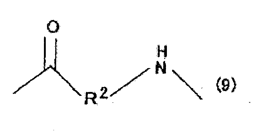


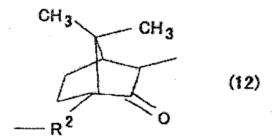


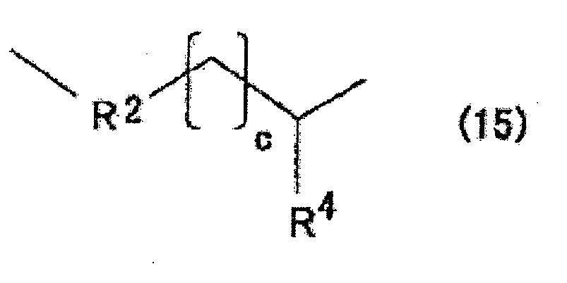


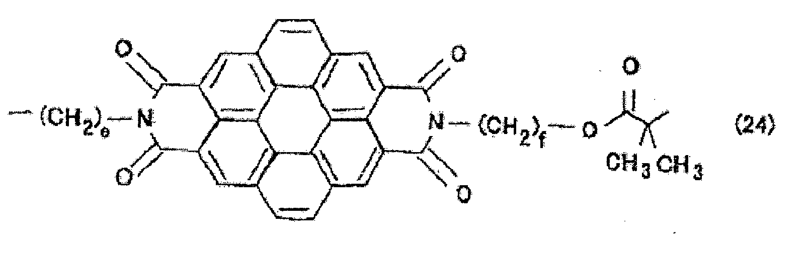


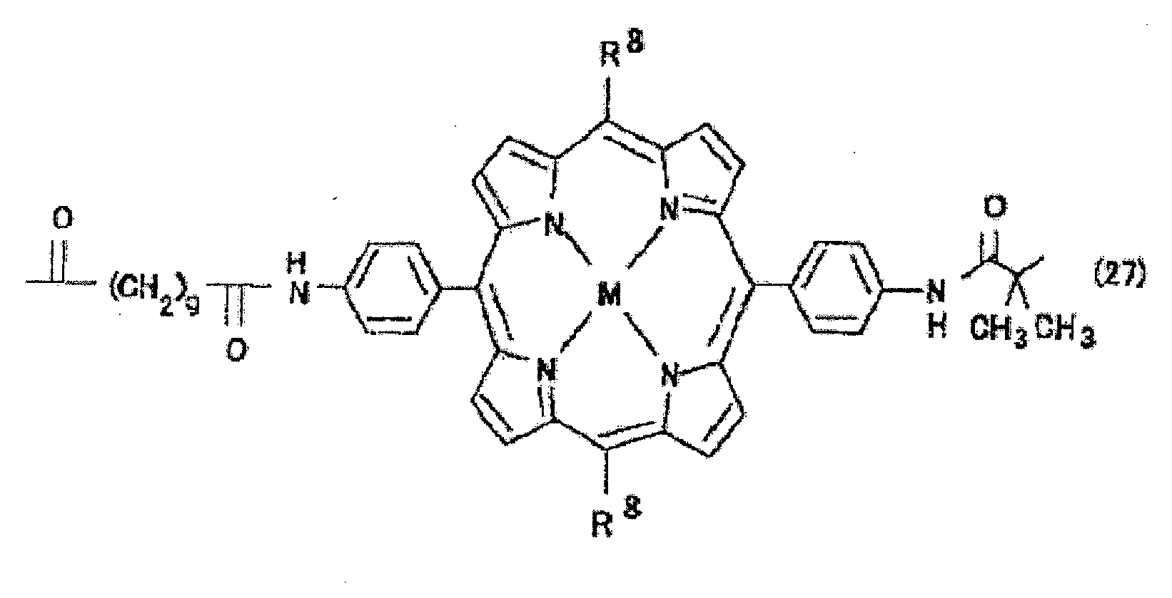


- Membrane de structure séparée en microphases selon la revendication 1, dans laquelle la distribution de masse moléculaire (Mw/Mn) du copolymère est de 1,4 ou moins.
- Membrane de structure séparée en microphases selon la revendication 1, dans laquelle le copolymère est représenté par la formule (1) suivante :


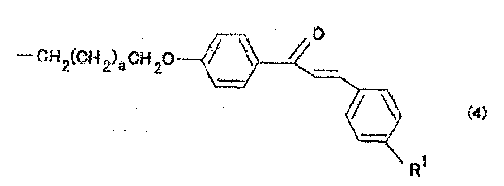


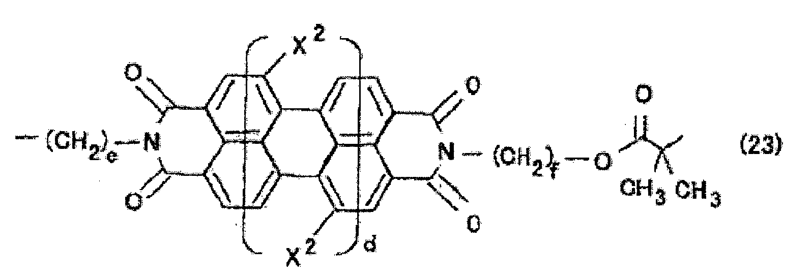


- Membrane de structure séparée en microphases selon l'une quelconque des revendications 1, 2 et 3, dans laquelle le groupe réactif est choisi dans le groupe consistant en les suivants :


- Membrane de structure séparée en microphases selon l'une quelconque des revendications 1, 2, 3 et 4, dans laquelle la structure de cylindre est une structure de cylindre hexagonale compacte.
- Membrane de structure séparée en microphases selon l'une quelconque des revendications 1, 2, 3, 4 et 5, dans laquelle la membrane est disposée sur un substrat.
- Structure poreuse dans laquelle des pores sont formés par gravage de la structure de cylindre dans une membrane de structure séparée en microphases selon l'une quelconque des revendications 1, 2, 3, 4, 5 et 6 par gravage.
- Procédé de production d'une membrane de structure séparée en microphases, le procédé comprenant les étapes :de préparation d'une solution de copolymère séquencé par dissolution d'un copolymère séquencé dans lequel un composé polymère hydrophile et un composé polymère hydrophobe sont couplés l'un à l'autre via un motif structural ayant un groupe réactif dans un solvant qui peut dissoudre le copolymère séquencé, où le composant polymère hydrophile est le poly(oxyde d'éthylène), et le composant polymère hydrophobe est un poly(acrylate) ou poly (méthacrylate) ayant une chaîne latérale mésogénique, et le motif structural ayant un groupe réactif est représenté par l'une quelconque des formules (5) à (32) ci-dessous ;d'application de la solution de copolymère séquencé à une surface du substrat ou d'addition goutte à goutte de la solution de copolymère séquencé dans un liquide qui ne dissout pas la solution ; etde formation d'une membrane de structure séparée en microphases du copolymère séquencé par évaporation du solvant,


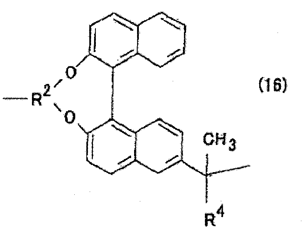


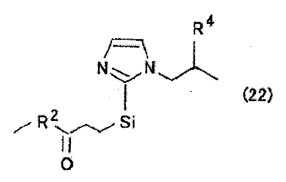


- Procédé de production d'une membrane de structure séparée en microphases selon la revendication 8, dans lequel la distribution de masse moléculaire (Mw/Mn) du copolymère est de 1,4 ou moins.
- Procédé de production d'une membrane de structure séparée en microphases selon la revendication 8, dans lequel le copolymère est représenté par la formule (1) suivante :
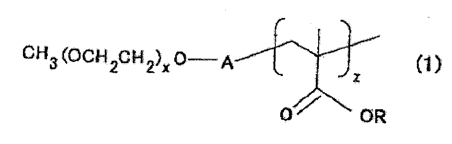


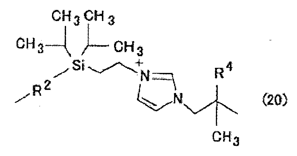


- Procédé de production d'une membrane de structure séparée en microphases selon l'une quelconque des revendications 8, 9 et 10, dans lequel le groupe réactif est choisi dans le groupe consistant en les suivants :


- Procédé de production d'une membrane de structure séparée en microphases selon l'une quelconque des revendications 8, 9, 10 et 11, dans lequel le substrat est un substrat constitué d'un matériau hydrophobe ou un substrat ayant une surface rendue hydrophobe.
- Procédé de production d'une membrane de structure séparée en microphases selon l'une quelconque des revendications 8, 9, 10, 11 et 12, dans lequel le solvant est évaporé par chauffage de la solution de copolymère séquencé.
- Procédé de production d'une membrane de structure séparée en microphases selon la revendication 13, dans lequel, en plus du traitement à la chaleur, la surface du substrat est soumise à un traitement d'orientation.
- Procédé de production d'une membrane de structure séparée en microphases selon la revendication 13 ou 14, dans lequel le traitement à la chaleur est conduit dans la plage de températures allant d'une température inférieure au point de fusion du copolymère séquencé de 10 °C à une température inférieure à la température de décomposition du copolymère séquencé.
- Structure poreuse constituée en contenant un composant polymère hydrophobe, la structure poreuse comprenant une pluralité de pores colonnaires ayant des surfaces incluant un motif structural ayant un groupe réactif, dans laquelle
le composant polymère hydrophobe est un poly(acrylate) ou poly(méthacrylate) ayant une chaîne latérale mésogénique, une longue chaîne latérale alkyle, ou une chaîne latérale hydrophobe ; et
le motif structural ayant un groupe réactif est représenté par l'une quelconque des formules (5') à (22') suivantes :


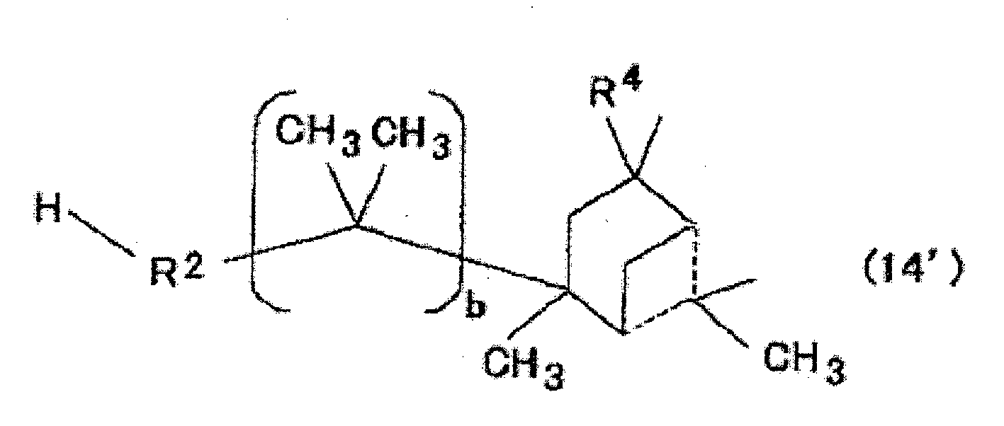


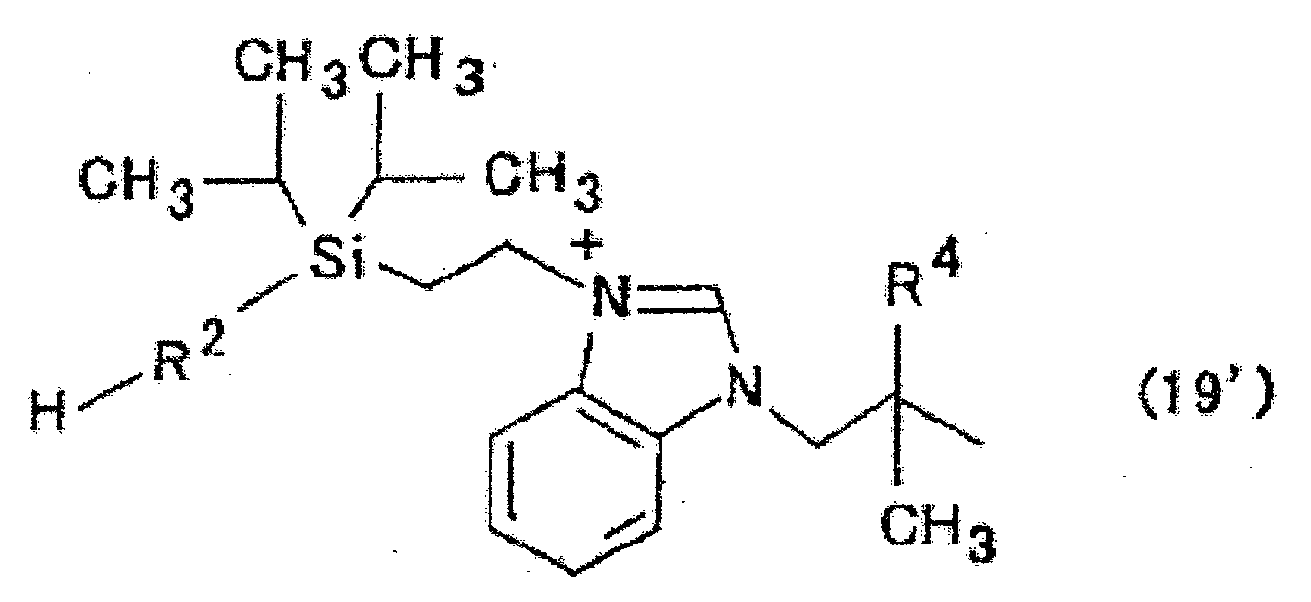


- Structure poreuse selon la revendication 16, dans laquelle le composant polymère hydrophobe a une structure représentée par la formule suivante :

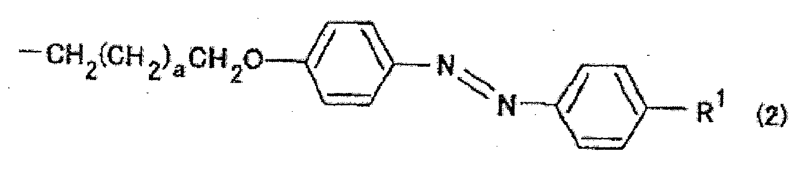


- Structure poreuse selon la revendication 16 ou 17, dans laquelle le groupe réactif est choisi dans le groupe consistant en les suivants :


- Electrolyte polymère pour pile à combustible comprenant une structure poreuse selon l'une quelconque des revendications 16, 17 et 18.
- Pile à combustible comprenant un électrolyte polymère pour pile à combustible selon la revendication 19.
- Procédé de production d'une structure poreuse, le procédé comprenant l'étape de formation de pores par gravage de la portion composant polymère hydrophile dans une membrane de structure séparée en microphases par un procédé selon l'une quelconque des revendications 8, 9, 10 et 11 à 15.
Applications Claiming Priority (2)
| Application Number | Priority Date | Filing Date | Title |
|---|---|---|---|
| JP2007227972A JP4403238B2 (ja) | 2007-09-03 | 2007-09-03 | ミクロ相分離構造膜、及びその製造方法 |
| PCT/JP2008/066142 WO2009031676A1 (fr) | 2007-09-03 | 2008-09-02 | Film de structure séparé en microphases et procédé de fabrication du film de structure séparé en microphases |
Publications (3)
| Publication Number | Publication Date |
|---|---|
| EP2199312A1 EP2199312A1 (fr) | 2010-06-23 |
| EP2199312A4 EP2199312A4 (fr) | 2011-06-15 |
| EP2199312B1 true EP2199312B1 (fr) | 2013-07-10 |
Family
ID=40428988
Family Applications (1)
| Application Number | Title | Priority Date | Filing Date |
|---|---|---|---|
| EP08828950.9A Not-in-force EP2199312B1 (fr) | 2007-09-03 | 2008-09-02 | Film de structure séparé en microphases, procédé de fabrication du film de structure séparé en microphases et pile à combustible |
Country Status (5)
| Country | Link |
|---|---|
| US (1) | US8476322B2 (fr) |
| EP (1) | EP2199312B1 (fr) |
| JP (1) | JP4403238B2 (fr) |
| CN (1) | CN101855258B (fr) |
| WO (1) | WO2009031676A1 (fr) |
Families Citing this family (44)
| Publication number | Priority date | Publication date | Assignee | Title |
|---|---|---|---|---|
| JP4403238B2 (ja) * | 2007-09-03 | 2010-01-27 | 国立大学法人東京工業大学 | ミクロ相分離構造膜、及びその製造方法 |
| JP5679253B2 (ja) * | 2009-05-26 | 2015-03-04 | 国立大学法人東京工業大学 | 自立性高分子薄膜 |
| JP5330527B2 (ja) | 2009-09-29 | 2013-10-30 | 株式会社東芝 | 構造体 |
| JP5477577B2 (ja) * | 2010-03-31 | 2014-04-23 | 凸版印刷株式会社 | ブロック共重合体、有機薄膜、光電変換素子及び太陽電池 |
| JP2012106216A (ja) * | 2010-11-19 | 2012-06-07 | Tokyo Electron Ltd | 濾過用フィルタ及びその製造方法 |
| CN104411739B (zh) * | 2012-05-02 | 2017-03-08 | 路博润高级材料公司 | 芳族分散剂组合物 |
| JP6415428B2 (ja) | 2012-05-02 | 2018-10-31 | ルブリゾル アドバンスド マテリアルズ, インコーポレイテッド | 芳香族分散剤組成物 |
| JP6100597B2 (ja) * | 2013-01-08 | 2017-03-22 | 富士フイルム株式会社 | ブロック共重合体、およびそれを用いたミクロ相分離構造膜、ならびにそれらの製造方法 |
| KR102270878B1 (ko) * | 2013-10-17 | 2021-06-29 | 린텍 가부시키가이샤 | 단열 필름 및 그의 제조 방법 |
| US10253362B2 (en) | 2013-11-08 | 2019-04-09 | Hitachi High-Technologies Corporation | DNA transport control device and method for producing same, as well as DNA sequencing device |
| JP6483693B2 (ja) | 2013-12-06 | 2019-03-13 | エルジー・ケム・リミテッド | ブロック共重合体 |
| JP6419820B2 (ja) | 2013-12-06 | 2018-11-07 | エルジー・ケム・リミテッド | ブロック共重合体 |
| WO2015084123A1 (fr) | 2013-12-06 | 2015-06-11 | 주식회사 엘지화학 | Copolymère bloc |
| CN105960422B (zh) | 2013-12-06 | 2019-01-18 | 株式会社Lg化学 | 嵌段共聚物 |
| WO2015084121A1 (fr) | 2013-12-06 | 2015-06-11 | 주식회사 엘지화학 | Copolymère bloc |
| JP6483694B2 (ja) | 2013-12-06 | 2019-03-13 | エルジー・ケム・リミテッド | 単量体およびブロック共重合体 |
| US10150832B2 (en) | 2013-12-06 | 2018-12-11 | Lg Chem, Ltd. | Block copolymer |
| WO2015084125A1 (fr) | 2013-12-06 | 2015-06-11 | 주식회사 엘지화학 | Copolymère bloc |
| JP6432847B2 (ja) | 2013-12-06 | 2018-12-05 | エルジー・ケム・リミテッド | ブロック共重合体 |
| WO2015084122A1 (fr) | 2013-12-06 | 2015-06-11 | 주식회사 엘지화학 | Copolymère bloc |
| JP6432846B2 (ja) | 2013-12-06 | 2018-12-05 | エルジー・ケム・リミテッド | ブロック共重合体 |
| WO2015084124A1 (fr) | 2013-12-06 | 2015-06-11 | 주식회사 엘지화학 | Copolymère bloc |
| JP6361893B2 (ja) | 2013-12-06 | 2018-07-25 | エルジー・ケム・リミテッド | ブロック共重合体 |
| WO2015084128A1 (fr) | 2013-12-06 | 2015-06-11 | 주식회사 엘지화학 | Copolymère bloc |
| US10240035B2 (en) | 2014-09-30 | 2019-03-26 | Lg Chem, Ltd. | Block copolymer |
| WO2016053005A1 (fr) | 2014-09-30 | 2016-04-07 | 주식회사 엘지화학 | Copolymère bloc |
| WO2016053009A1 (fr) | 2014-09-30 | 2016-04-07 | 주식회사 엘지화학 | Copolymère bloc |
| EP3214102B1 (fr) | 2014-09-30 | 2022-01-05 | LG Chem, Ltd. | Copolymère bloc |
| JP6505212B2 (ja) | 2014-09-30 | 2019-04-24 | エルジー・ケム・リミテッド | ブロック共重合体 |
| US10633533B2 (en) | 2014-09-30 | 2020-04-28 | Lg Chem, Ltd. | Block copolymer |
| JP6538158B2 (ja) | 2014-09-30 | 2019-07-03 | エルジー・ケム・リミテッド | ブロック共重合体 |
| US10287430B2 (en) | 2014-09-30 | 2019-05-14 | Lg Chem, Ltd. | Method of manufacturing patterned substrate |
| JP6633062B2 (ja) | 2014-09-30 | 2020-01-22 | エルジー・ケム・リミテッド | パターン化基板の製造方法 |
| EP3202798B1 (fr) * | 2014-09-30 | 2022-01-12 | LG Chem, Ltd. | Copolymère bloc |
| KR102329387B1 (ko) * | 2014-10-10 | 2021-11-22 | 삼성디스플레이 주식회사 | 고분자 일렉트렛트 및 이의 제조방법 |
| JP6472208B2 (ja) * | 2014-10-24 | 2019-02-20 | 株式会社日立ハイテクノロジーズ | 核酸搬送制御デバイス及びその製造方法、並びに核酸シーケンシング装置 |
| JP6524704B2 (ja) * | 2015-02-26 | 2019-06-05 | 住友ベークライト株式会社 | 遷移金属錯体を含有するブロック共重合体 |
| JP6637705B2 (ja) * | 2015-09-14 | 2020-01-29 | 智一 彌田 | 相分離構造膜及びその製造方法 |
| EP3369474A1 (fr) * | 2017-03-01 | 2018-09-05 | Helmholtz-Zentrum Geesthacht Zentrum für Material- und Küstenforschung GmbH | Membrane de copolymere isoporeuse sous forme feuille plate |
| CN111712468A (zh) * | 2017-12-22 | 2020-09-25 | 北卡罗莱纳州立大学 | 聚合物荧光团、包含其的组合物及制备和使用其的方法 |
| CN110943238B (zh) * | 2018-09-21 | 2020-11-20 | 中国科学院大连化学物理研究所 | 一种液流电池用离子传导膜及其制备和应用 |
| CN109575335B (zh) * | 2018-11-12 | 2021-07-30 | 湘潭大学 | 一种调控纳米结构取向的方法 |
| CN112898857B (zh) * | 2021-01-20 | 2022-02-08 | 南方科技大学 | 一种高分子压力敏感漆及其制备方法和应用 |
| CN116212637B (zh) * | 2022-12-08 | 2024-10-01 | 中国科学技术大学 | 一种基于聚离子液体刷功能化的超滤膜及其制备方法和应用 |
Family Cites Families (10)
| Publication number | Priority date | Publication date | Assignee | Title |
|---|---|---|---|---|
| JP3940546B2 (ja) * | 1999-06-07 | 2007-07-04 | 株式会社東芝 | パターン形成方法およびパターン形成材料 |
| JP4127682B2 (ja) * | 1999-06-07 | 2008-07-30 | 株式会社東芝 | パターン形成方法 |
| JP2004502554A (ja) | 2000-03-22 | 2004-01-29 | ユニバーシティー オブ マサチューセッツ | ナノシリンダー・アレイ |
| JP2002155113A (ja) * | 2000-11-20 | 2002-05-28 | Science Univ Of Tokyo | カルコン誘導体を有する新規液晶高分子の製造方法およびそれらの光橋かけ膜材料の液晶配向特性 |
| JP3979470B2 (ja) * | 2002-09-11 | 2007-09-19 | 財団法人理工学振興会 | ブロック共重合体、及びミクロ相分離構造膜の製造方法 |
| JP5135571B2 (ja) * | 2005-03-28 | 2013-02-06 | 国立大学法人東京工業大学 | 異方性イオン伝導性高分子膜 |
| JP4633569B2 (ja) * | 2005-07-27 | 2011-02-16 | 三井化学株式会社 | 架橋型プロトン伝導性ブロック共重合体、その架橋体ならびにそれを用いたプロトン伝導膜および燃料電池 |
| JP4887486B2 (ja) * | 2005-11-08 | 2012-02-29 | 国立大学法人東京工業大学 | カルコン類縁体 |
| WO2007055371A1 (fr) * | 2005-11-14 | 2007-05-18 | Tokyo Institute Of Technology | Procede de fabrication d'un substrat nanoporeux |
| JP4403238B2 (ja) * | 2007-09-03 | 2010-01-27 | 国立大学法人東京工業大学 | ミクロ相分離構造膜、及びその製造方法 |
-
2007
- 2007-09-03 JP JP2007227972A patent/JP4403238B2/ja not_active Expired - Fee Related
-
2008
- 2008-09-02 US US12/675,955 patent/US8476322B2/en not_active Expired - Fee Related
- 2008-09-02 EP EP08828950.9A patent/EP2199312B1/fr not_active Not-in-force
- 2008-09-02 WO PCT/JP2008/066142 patent/WO2009031676A1/fr not_active Ceased
- 2008-09-02 CN CN2008801137818A patent/CN101855258B/zh not_active Expired - Fee Related
Also Published As
| Publication number | Publication date |
|---|---|
| EP2199312A4 (fr) | 2011-06-15 |
| US20100210742A1 (en) | 2010-08-19 |
| JP2009057519A (ja) | 2009-03-19 |
| US8476322B2 (en) | 2013-07-02 |
| JP4403238B2 (ja) | 2010-01-27 |
| WO2009031676A1 (fr) | 2009-03-12 |
| CN101855258B (zh) | 2013-07-10 |
| CN101855258A (zh) | 2010-10-06 |
| EP2199312A1 (fr) | 2010-06-23 |
Similar Documents
| Publication | Publication Date | Title |
|---|---|---|
| EP2199312B1 (fr) | Film de structure séparé en microphases, procédé de fabrication du film de structure séparé en microphases et pile à combustible | |
| Fei et al. | Ordered nanoporous carbons with broadly tunable pore size using bottlebrush block copolymer templates | |
| JP5679253B2 (ja) | 自立性高分子薄膜 | |
| EP3203497B1 (fr) | Procédé de fabrication d'un substrat à motifs | |
| Percec et al. | Detecting the shape change of complex macromolecules during their synthesis with the aid of kinetics. A new lesson from biology | |
| EP3078690B1 (fr) | Copolymère bloc | |
| KR101749415B1 (ko) | 블록 공중합체 | |
| Schulze et al. | Tuning mesoporosity in cross-linked nanostructured thermosets via polymerization-induced microphase separation | |
| EP3078693B1 (fr) | Copolymère bloc | |
| EP3202800A1 (fr) | Copolymère bloc | |
| EP3225641A1 (fr) | Copolymère séquencé | |
| Lang et al. | Biomimetic separation of transport and matrix functions in lamellar block copolymer channel-based membranes | |
| Park et al. | Structure–Property Relationships in Single-Ion Conducting Multiblock Copolymers: A Phase Diagram and Ionic Conductivities | |
| Rahman et al. | Synthesis and self-assembly studies of amphiphilic poly (n-hexyl isocyanate)-b lock-poly (2-vinylpyridine)-b lock-poly (n-hexyl isocyanate) rod− coil− rod triblock copolymer | |
| Yan et al. | Metallopolymers from organically modified polyoxometalates (MOMPs): A review | |
| KR101254653B1 (ko) | 음이온 교환성 고분자로 코팅된 탄소전극 제조 방법 | |
| Fultz et al. | Nanostructured films of oppositely charged domains from self-assembled block copolymers | |
| JP2013027964A (ja) | 微細構造体の製造方法、複合体 | |
| Xie et al. | Poly (ionic liquid) membranes preserving liquid crystalline microstructures for lithium-ion enrichment | |
| JP4297831B2 (ja) | 配向の制御されたミクロ相分離構造膜の製法 | |
| He et al. | Pyrrole-containing ABA triblock brush polymers as dual functional molecules to facilely access diverse mesostructured materials | |
| Sun et al. | Anion exchange membranes with orderly channels enabled by charge transfer interactions for fast transportation of Cl− | |
| JP2008115286A (ja) | フラーレンを規則的に配列させて含有する高分子膜 | |
| JP2005259392A (ja) | 異方的イオン伝導性液晶化学ゲルとその製造方法 | |
| 박보영 et al. | Synthesis and application of nitrogen doped graphene nanoplatelets |
Legal Events
| Date | Code | Title | Description |
|---|---|---|---|
| PUAI | Public reference made under article 153(3) epc to a published international application that has entered the european phase |
Free format text: ORIGINAL CODE: 0009012 |
|
| 17P | Request for examination filed |
Effective date: 20100301 |
|
| AK | Designated contracting states |
Kind code of ref document: A1 Designated state(s): AT BE BG CH CY CZ DE DK EE ES FI FR GB GR HR HU IE IS IT LI LT LU LV MC MT NL NO PL PT RO SE SI SK TR |
|
| AX | Request for extension of the european patent |
Extension state: AL BA MK RS |
|
| DAX | Request for extension of the european patent (deleted) | ||
| A4 | Supplementary search report drawn up and despatched |
Effective date: 20110518 |
|
| RIC1 | Information provided on ipc code assigned before grant |
Ipc: H01B 1/06 20060101ALI20120712BHEP Ipc: H01M 8/02 20060101ALI20120712BHEP Ipc: C08J 5/22 20060101ALI20120712BHEP Ipc: C09D 153/00 20060101ALI20120712BHEP Ipc: C08J 5/20 20060101ALI20120712BHEP Ipc: H01B 1/12 20060101ALI20120712BHEP Ipc: C08J 9/26 20060101ALI20120712BHEP Ipc: C08F 293/00 20060101AFI20120712BHEP Ipc: H01M 8/10 20060101ALI20120712BHEP |
|
| 17Q | First examination report despatched |
Effective date: 20120718 |
|
| GRAP | Despatch of communication of intention to grant a patent |
Free format text: ORIGINAL CODE: EPIDOSNIGR1 |
|
| RAP1 | Party data changed (applicant data changed or rights of an application transferred) |
Owner name: TOYOTA JIDOSHA KABUSHIKI KAISHA Owner name: TOKYO INSTITUTE OF TECHNOLOGY |
|
| GRAS | Grant fee paid |
Free format text: ORIGINAL CODE: EPIDOSNIGR3 |
|
| GRAA | (expected) grant |
Free format text: ORIGINAL CODE: 0009210 |
|
| AK | Designated contracting states |
Kind code of ref document: B1 Designated state(s): AT BE BG CH CY CZ DE DK EE ES FI FR GB GR HR HU IE IS IT LI LT LU LV MC MT NL NO PL PT RO SE SI SK TR |
|
| REG | Reference to a national code |
Ref country code: GB Ref legal event code: FG4D |
|
| REG | Reference to a national code |
Ref country code: AT Ref legal event code: REF Ref document number: 620961 Country of ref document: AT Kind code of ref document: T Effective date: 20130715 Ref country code: CH Ref legal event code: EP |
|
| REG | Reference to a national code |
Ref country code: IE Ref legal event code: FG4D |
|
| REG | Reference to a national code |
Ref country code: DE Ref legal event code: R096 Ref document number: 602008025957 Country of ref document: DE Effective date: 20130905 |
|
| PG25 | Lapsed in a contracting state [announced via postgrant information from national office to epo] |
Ref country code: SI Free format text: LAPSE BECAUSE OF FAILURE TO SUBMIT A TRANSLATION OF THE DESCRIPTION OR TO PAY THE FEE WITHIN THE PRESCRIBED TIME-LIMIT Effective date: 20130710 |
|
| REG | Reference to a national code |
Ref country code: AT Ref legal event code: MK05 Ref document number: 620961 Country of ref document: AT Kind code of ref document: T Effective date: 20130710 |
|
| REG | Reference to a national code |
Ref country code: NL Ref legal event code: VDEP Effective date: 20130710 |
|
| REG | Reference to a national code |
Ref country code: LT Ref legal event code: MG4D |
|
| PG25 | Lapsed in a contracting state [announced via postgrant information from national office to epo] |
Ref country code: CY Free format text: LAPSE BECAUSE OF FAILURE TO SUBMIT A TRANSLATION OF THE DESCRIPTION OR TO PAY THE FEE WITHIN THE PRESCRIBED TIME-LIMIT Effective date: 20130828 Ref country code: PT Free format text: LAPSE BECAUSE OF FAILURE TO SUBMIT A TRANSLATION OF THE DESCRIPTION OR TO PAY THE FEE WITHIN THE PRESCRIBED TIME-LIMIT Effective date: 20131111 Ref country code: NO Free format text: LAPSE BECAUSE OF FAILURE TO SUBMIT A TRANSLATION OF THE DESCRIPTION OR TO PAY THE FEE WITHIN THE PRESCRIBED TIME-LIMIT Effective date: 20131010 Ref country code: HR Free format text: LAPSE BECAUSE OF FAILURE TO SUBMIT A TRANSLATION OF THE DESCRIPTION OR TO PAY THE FEE WITHIN THE PRESCRIBED TIME-LIMIT Effective date: 20130710 Ref country code: LT Free format text: LAPSE BECAUSE OF FAILURE TO SUBMIT A TRANSLATION OF THE DESCRIPTION OR TO PAY THE FEE WITHIN THE PRESCRIBED TIME-LIMIT Effective date: 20130710 Ref country code: SE Free format text: LAPSE BECAUSE OF FAILURE TO SUBMIT A TRANSLATION OF THE DESCRIPTION OR TO PAY THE FEE WITHIN THE PRESCRIBED TIME-LIMIT Effective date: 20130710 Ref country code: AT Free format text: LAPSE BECAUSE OF FAILURE TO SUBMIT A TRANSLATION OF THE DESCRIPTION OR TO PAY THE FEE WITHIN THE PRESCRIBED TIME-LIMIT Effective date: 20130710 Ref country code: BE Free format text: LAPSE BECAUSE OF FAILURE TO SUBMIT A TRANSLATION OF THE DESCRIPTION OR TO PAY THE FEE WITHIN THE PRESCRIBED TIME-LIMIT Effective date: 20130710 Ref country code: IS Free format text: LAPSE BECAUSE OF FAILURE TO SUBMIT A TRANSLATION OF THE DESCRIPTION OR TO PAY THE FEE WITHIN THE PRESCRIBED TIME-LIMIT Effective date: 20131110 |
|
| PG25 | Lapsed in a contracting state [announced via postgrant information from national office to epo] |
Ref country code: PL Free format text: LAPSE BECAUSE OF FAILURE TO SUBMIT A TRANSLATION OF THE DESCRIPTION OR TO PAY THE FEE WITHIN THE PRESCRIBED TIME-LIMIT Effective date: 20130710 Ref country code: FI Free format text: LAPSE BECAUSE OF FAILURE TO SUBMIT A TRANSLATION OF THE DESCRIPTION OR TO PAY THE FEE WITHIN THE PRESCRIBED TIME-LIMIT Effective date: 20130710 Ref country code: LV Free format text: LAPSE BECAUSE OF FAILURE TO SUBMIT A TRANSLATION OF THE DESCRIPTION OR TO PAY THE FEE WITHIN THE PRESCRIBED TIME-LIMIT Effective date: 20130710 Ref country code: ES Free format text: LAPSE BECAUSE OF FAILURE TO SUBMIT A TRANSLATION OF THE DESCRIPTION OR TO PAY THE FEE WITHIN THE PRESCRIBED TIME-LIMIT Effective date: 20131021 Ref country code: NL Free format text: LAPSE BECAUSE OF FAILURE TO SUBMIT A TRANSLATION OF THE DESCRIPTION OR TO PAY THE FEE WITHIN THE PRESCRIBED TIME-LIMIT Effective date: 20130710 Ref country code: GR Free format text: LAPSE BECAUSE OF FAILURE TO SUBMIT A TRANSLATION OF THE DESCRIPTION OR TO PAY THE FEE WITHIN THE PRESCRIBED TIME-LIMIT Effective date: 20131011 |
|
| PG25 | Lapsed in a contracting state [announced via postgrant information from national office to epo] |
Ref country code: CY Free format text: LAPSE BECAUSE OF FAILURE TO SUBMIT A TRANSLATION OF THE DESCRIPTION OR TO PAY THE FEE WITHIN THE PRESCRIBED TIME-LIMIT Effective date: 20130710 |
|
| PG25 | Lapsed in a contracting state [announced via postgrant information from national office to epo] |
Ref country code: MC Free format text: LAPSE BECAUSE OF FAILURE TO SUBMIT A TRANSLATION OF THE DESCRIPTION OR TO PAY THE FEE WITHIN THE PRESCRIBED TIME-LIMIT Effective date: 20130710 Ref country code: DK Free format text: LAPSE BECAUSE OF FAILURE TO SUBMIT A TRANSLATION OF THE DESCRIPTION OR TO PAY THE FEE WITHIN THE PRESCRIBED TIME-LIMIT Effective date: 20130710 Ref country code: SK Free format text: LAPSE BECAUSE OF FAILURE TO SUBMIT A TRANSLATION OF THE DESCRIPTION OR TO PAY THE FEE WITHIN THE PRESCRIBED TIME-LIMIT Effective date: 20130710 Ref country code: RO Free format text: LAPSE BECAUSE OF FAILURE TO SUBMIT A TRANSLATION OF THE DESCRIPTION OR TO PAY THE FEE WITHIN THE PRESCRIBED TIME-LIMIT Effective date: 20130710 Ref country code: CZ Free format text: LAPSE BECAUSE OF FAILURE TO SUBMIT A TRANSLATION OF THE DESCRIPTION OR TO PAY THE FEE WITHIN THE PRESCRIBED TIME-LIMIT Effective date: 20130710 Ref country code: EE Free format text: LAPSE BECAUSE OF FAILURE TO SUBMIT A TRANSLATION OF THE DESCRIPTION OR TO PAY THE FEE WITHIN THE PRESCRIBED TIME-LIMIT Effective date: 20130710 |
|
| REG | Reference to a national code |
Ref country code: CH Ref legal event code: PL |
|
| PLBE | No opposition filed within time limit |
Free format text: ORIGINAL CODE: 0009261 |
|
| STAA | Information on the status of an ep patent application or granted ep patent |
Free format text: STATUS: NO OPPOSITION FILED WITHIN TIME LIMIT |
|
| PG25 | Lapsed in a contracting state [announced via postgrant information from national office to epo] |
Ref country code: IT Free format text: LAPSE BECAUSE OF FAILURE TO SUBMIT A TRANSLATION OF THE DESCRIPTION OR TO PAY THE FEE WITHIN THE PRESCRIBED TIME-LIMIT Effective date: 20130710 |
|
| 26N | No opposition filed |
Effective date: 20140411 |
|
| REG | Reference to a national code |
Ref country code: IE Ref legal event code: MM4A |
|
| REG | Reference to a national code |
Ref country code: DE Ref legal event code: R097 Ref document number: 602008025957 Country of ref document: DE Effective date: 20140411 |
|
| PG25 | Lapsed in a contracting state [announced via postgrant information from national office to epo] |
Ref country code: IE Free format text: LAPSE BECAUSE OF NON-PAYMENT OF DUE FEES Effective date: 20130902 Ref country code: CH Free format text: LAPSE BECAUSE OF NON-PAYMENT OF DUE FEES Effective date: 20130930 Ref country code: LI Free format text: LAPSE BECAUSE OF NON-PAYMENT OF DUE FEES Effective date: 20130930 |
|
| PG25 | Lapsed in a contracting state [announced via postgrant information from national office to epo] |
Ref country code: MT Free format text: LAPSE BECAUSE OF FAILURE TO SUBMIT A TRANSLATION OF THE DESCRIPTION OR TO PAY THE FEE WITHIN THE PRESCRIBED TIME-LIMIT Effective date: 20130710 Ref country code: TR Free format text: LAPSE BECAUSE OF FAILURE TO SUBMIT A TRANSLATION OF THE DESCRIPTION OR TO PAY THE FEE WITHIN THE PRESCRIBED TIME-LIMIT Effective date: 20130710 |
|
| PG25 | Lapsed in a contracting state [announced via postgrant information from national office to epo] |
Ref country code: LU Free format text: LAPSE BECAUSE OF NON-PAYMENT OF DUE FEES Effective date: 20130902 Ref country code: BG Free format text: LAPSE BECAUSE OF FAILURE TO SUBMIT A TRANSLATION OF THE DESCRIPTION OR TO PAY THE FEE WITHIN THE PRESCRIBED TIME-LIMIT Effective date: 20130710 Ref country code: HU Free format text: LAPSE BECAUSE OF FAILURE TO SUBMIT A TRANSLATION OF THE DESCRIPTION OR TO PAY THE FEE WITHIN THE PRESCRIBED TIME-LIMIT; INVALID AB INITIO Effective date: 20080902 |
|
| REG | Reference to a national code |
Ref country code: FR Ref legal event code: PLFP Year of fee payment: 8 |
|
| REG | Reference to a national code |
Ref country code: FR Ref legal event code: PLFP Year of fee payment: 9 |
|
| PGFP | Annual fee paid to national office [announced via postgrant information from national office to epo] |
Ref country code: GB Payment date: 20160831 Year of fee payment: 9 Ref country code: DE Payment date: 20160830 Year of fee payment: 9 |
|
| PGFP | Annual fee paid to national office [announced via postgrant information from national office to epo] |
Ref country code: FR Payment date: 20160826 Year of fee payment: 9 |
|
| REG | Reference to a national code |
Ref country code: DE Ref legal event code: R119 Ref document number: 602008025957 Country of ref document: DE |
|
| GBPC | Gb: european patent ceased through non-payment of renewal fee |
Effective date: 20170902 |
|
| REG | Reference to a national code |
Ref country code: FR Ref legal event code: ST Effective date: 20180531 |
|
| PG25 | Lapsed in a contracting state [announced via postgrant information from national office to epo] |
Ref country code: DE Free format text: LAPSE BECAUSE OF NON-PAYMENT OF DUE FEES Effective date: 20180404 Ref country code: GB Free format text: LAPSE BECAUSE OF NON-PAYMENT OF DUE FEES Effective date: 20170902 |
|
| PG25 | Lapsed in a contracting state [announced via postgrant information from national office to epo] |
Ref country code: FR Free format text: LAPSE BECAUSE OF NON-PAYMENT OF DUE FEES Effective date: 20171002 |