EP2199364A2 - Gegenstromverfahren zur Umwandlung von Biomasse - Google Patents
Gegenstromverfahren zur Umwandlung von Biomasse Download PDFInfo
- Publication number
- EP2199364A2 EP2199364A2 EP08171256A EP08171256A EP2199364A2 EP 2199364 A2 EP2199364 A2 EP 2199364A2 EP 08171256 A EP08171256 A EP 08171256A EP 08171256 A EP08171256 A EP 08171256A EP 2199364 A2 EP2199364 A2 EP 2199364A2
- Authority
- EP
- European Patent Office
- Prior art keywords
- reactor
- temperature
- biomass
- catalyst
- heat carrier
- Prior art date
- Legal status (The legal status is an assumption and is not a legal conclusion. Google has not performed a legal analysis and makes no representation as to the accuracy of the status listed.)
- Withdrawn
Links
Images


Classifications
-
- C—CHEMISTRY; METALLURGY
- C10—PETROLEUM, GAS OR COKE INDUSTRIES; TECHNICAL GASES CONTAINING CARBON MONOXIDE; FUELS; LUBRICANTS; PEAT
- C10B—DESTRUCTIVE DISTILLATION OF CARBONACEOUS MATERIALS FOR PRODUCTION OF GAS, COKE, TAR, OR SIMILAR MATERIALS
- C10B49/00—Destructive distillation of solid carbonaceous materials by direct heating with heat-carrying agents including the partial combustion of the solid material to be treated
- C10B49/02—Destructive distillation of solid carbonaceous materials by direct heating with heat-carrying agents including the partial combustion of the solid material to be treated with hot gases or vapours, e.g. hot gases obtained by partial combustion of the charge
-
- C—CHEMISTRY; METALLURGY
- C10—PETROLEUM, GAS OR COKE INDUSTRIES; TECHNICAL GASES CONTAINING CARBON MONOXIDE; FUELS; LUBRICANTS; PEAT
- C10B—DESTRUCTIVE DISTILLATION OF CARBONACEOUS MATERIALS FOR PRODUCTION OF GAS, COKE, TAR, OR SIMILAR MATERIALS
- C10B49/00—Destructive distillation of solid carbonaceous materials by direct heating with heat-carrying agents including the partial combustion of the solid material to be treated
- C10B49/16—Destructive distillation of solid carbonaceous materials by direct heating with heat-carrying agents including the partial combustion of the solid material to be treated with moving solid heat-carriers in divided form
-
- C—CHEMISTRY; METALLURGY
- C10—PETROLEUM, GAS OR COKE INDUSTRIES; TECHNICAL GASES CONTAINING CARBON MONOXIDE; FUELS; LUBRICANTS; PEAT
- C10B—DESTRUCTIVE DISTILLATION OF CARBONACEOUS MATERIALS FOR PRODUCTION OF GAS, COKE, TAR, OR SIMILAR MATERIALS
- C10B53/00—Destructive distillation, specially adapted for particular solid raw materials or solid raw materials in special form
- C10B53/02—Destructive distillation, specially adapted for particular solid raw materials or solid raw materials in special form of cellulose-containing material
-
- C—CHEMISTRY; METALLURGY
- C10—PETROLEUM, GAS OR COKE INDUSTRIES; TECHNICAL GASES CONTAINING CARBON MONOXIDE; FUELS; LUBRICANTS; PEAT
- C10G—CRACKING HYDROCARBON OILS; PRODUCTION OF LIQUID HYDROCARBON MIXTURES, e.g. BY DESTRUCTIVE HYDROGENATION, OLIGOMERISATION, POLYMERISATION; RECOVERY OF HYDROCARBON OILS FROM OIL-SHALE, OIL-SAND, OR GASES; REFINING MIXTURES MAINLY CONSISTING OF HYDROCARBONS; REFORMING OF NAPHTHA; MINERAL WAXES
- C10G3/00—Production of liquid hydrocarbon mixtures from oxygen-containing organic materials, e.g. fatty oils, fatty acids
-
- C—CHEMISTRY; METALLURGY
- C10—PETROLEUM, GAS OR COKE INDUSTRIES; TECHNICAL GASES CONTAINING CARBON MONOXIDE; FUELS; LUBRICANTS; PEAT
- C10L—FUELS NOT OTHERWISE PROVIDED FOR; NATURAL GAS; SYNTHETIC NATURAL GAS OBTAINED BY PROCESSES NOT COVERED BY SUBCLASSES C10G OR C10K; LIQUIFIED PETROLEUM GAS; USE OF ADDITIVES TO FUELS OR FIRES; FIRE-LIGHTERS
- C10L1/00—Liquid carbonaceous fuels
- C10L1/02—Liquid carbonaceous fuels essentially based on components consisting of carbon, hydrogen, and oxygen only
- C10L1/026—Liquid carbonaceous fuels essentially based on components consisting of carbon, hydrogen, and oxygen only for compression ignition
-
- C—CHEMISTRY; METALLURGY
- C10—PETROLEUM, GAS OR COKE INDUSTRIES; TECHNICAL GASES CONTAINING CARBON MONOXIDE; FUELS; LUBRICANTS; PEAT
- C10G—CRACKING HYDROCARBON OILS; PRODUCTION OF LIQUID HYDROCARBON MIXTURES, e.g. BY DESTRUCTIVE HYDROGENATION, OLIGOMERISATION, POLYMERISATION; RECOVERY OF HYDROCARBON OILS FROM OIL-SHALE, OIL-SAND, OR GASES; REFINING MIXTURES MAINLY CONSISTING OF HYDROCARBONS; REFORMING OF NAPHTHA; MINERAL WAXES
- C10G2300/00—Aspects relating to hydrocarbon processing covered by groups C10G1/00 - C10G99/00
- C10G2300/10—Feedstock materials
- C10G2300/1011—Biomass
-
- Y—GENERAL TAGGING OF NEW TECHNOLOGICAL DEVELOPMENTS; GENERAL TAGGING OF CROSS-SECTIONAL TECHNOLOGIES SPANNING OVER SEVERAL SECTIONS OF THE IPC; TECHNICAL SUBJECTS COVERED BY FORMER USPC CROSS-REFERENCE ART COLLECTIONS [XRACs] AND DIGESTS
- Y02—TECHNOLOGIES OR APPLICATIONS FOR MITIGATION OR ADAPTATION AGAINST CLIMATE CHANGE
- Y02E—REDUCTION OF GREENHOUSE GAS [GHG] EMISSIONS, RELATED TO ENERGY GENERATION, TRANSMISSION OR DISTRIBUTION
- Y02E50/00—Technologies for the production of fuel of non-fossil origin
- Y02E50/10—Biofuels, e.g. bio-diesel
-
- Y—GENERAL TAGGING OF NEW TECHNOLOGICAL DEVELOPMENTS; GENERAL TAGGING OF CROSS-SECTIONAL TECHNOLOGIES SPANNING OVER SEVERAL SECTIONS OF THE IPC; TECHNICAL SUBJECTS COVERED BY FORMER USPC CROSS-REFERENCE ART COLLECTIONS [XRACs] AND DIGESTS
- Y02—TECHNOLOGIES OR APPLICATIONS FOR MITIGATION OR ADAPTATION AGAINST CLIMATE CHANGE
- Y02E—REDUCTION OF GREENHOUSE GAS [GHG] EMISSIONS, RELATED TO ENERGY GENERATION, TRANSMISSION OR DISTRIBUTION
- Y02E50/00—Technologies for the production of fuel of non-fossil origin
- Y02E50/30—Fuel from waste, e.g. synthetic alcohol or diesel
-
- Y—GENERAL TAGGING OF NEW TECHNOLOGICAL DEVELOPMENTS; GENERAL TAGGING OF CROSS-SECTIONAL TECHNOLOGIES SPANNING OVER SEVERAL SECTIONS OF THE IPC; TECHNICAL SUBJECTS COVERED BY FORMER USPC CROSS-REFERENCE ART COLLECTIONS [XRACs] AND DIGESTS
- Y02—TECHNOLOGIES OR APPLICATIONS FOR MITIGATION OR ADAPTATION AGAINST CLIMATE CHANGE
- Y02P—CLIMATE CHANGE MITIGATION TECHNOLOGIES IN THE PRODUCTION OR PROCESSING OF GOODS
- Y02P30/00—Technologies relating to oil refining and petrochemical industry
- Y02P30/20—Technologies relating to oil refining and petrochemical industry using bio-feedstock
Definitions
- the invention relates generally to the conversion of biomass material, and more particularly to the catalytic conversion of biomass material to liquid fuel products.
- Flash pyrolysis processes have been proposed in a number of variants.
- the main characteristics that such processes have in common are as follows.
- Biomass material is introduced into a hot reaction chamber, with or without a particulate heat carrier material. If a heat carrier material is used, this material may be an inert material, a catalytic material, or a combination of the two.
- An inert gas is used to remove the vaporized and gaseous reaction products from the reaction chamber, by volume replacement.
- the vaporized reaction products and the gaseous reaction products are entrained in the inert gas flow to a condensor, where the vaporized reaction products are condensed to liquid form, and separated from the inert gas stream and from the gaseous reaction products.
- the residence time of the reaction products in the reaction chamber may be short (residence times of less than 1 second are claimed by most authors), the reaction products remain at a high temperature until they reach the condensor. Consequently there is considerable opportunity of secondary reactions taking place with the unstable bio-oil components. This problem is aggravated by the fact that, in order to obtain acceptable yields, the reaction chamber is kept at a high temperature, typically at or near 500°C.
- the present invention addresses these problems by providing a countercurrent process for the catalytic conversion of biomass material, said process comprising the steps of:
- Another aspect of the invention is a bio-oil produced by this countercurrent process.
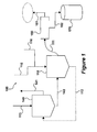
- FIG. 1 is a schematic representation of a prior art flash pyrolysis unit
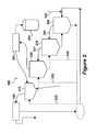
- FIG. 2 is a schematic representation of a first embodiment of the process of the invention
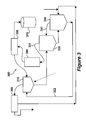
- FIG. 3 is a schematic representation of a variant of the embodiment of Figure 2 ;
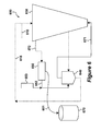
- Fig. 4 is a schematic representation of a second embodiment of the process of the invention.
- Fig. 5 is a schematic representation of a third embodiment of the process of the invention.
- the present invention relates to a countercurrent process for the catalytic conversion of biomass material, said process comprising the steps of:
- An essential aspect of the invention is that an important part of the biomass conversion reaction takes place at the lower temperature, T 1 , and that reaction products formed at this temperature are not exposed to the higher temperature T 2 . Biomass material that is not converted at the lower temperature T 1 is later exposed to the higher temperature, T 2 , for further conversion.
- T 1 and T 2 generally differ by 50 to 200 °C.
- step (ii) comprises mixing the solid particulate biomass material with a hot heat carrier material.
- step (ii) and during later stages of the process coke and/or char deposits on the heat carrier material.
- the coke and char deposits are burned off the particulate heat carrier material in a regenerator. The combustion heat of the coke and char is used to supply the necessary reaction heat to the heat carrier material.
- the particulate heat carrier material may be an inert material, such as sand, or it may be a catalytic material.
- catalytic material refers to a material that, by virtue of its presence in the reaction zone, affects at least one of the process parameters conversion yield and product distribution, without itself being consumed in the reaction.
- Examples of catalytic materials include the salts, oxides and hydroxides of the alkali metals and the earth alkaline metals, alumina, alumino-silicates, clays, hydrotalcites and hydrotalcite-like materials, ash from the biomass conversion process, and the like. Mixtures of such materials may also be used.
- hydrotalcite refers to the hydroxycarbonate having the empirical formula Mg 6 Al 2 (CO 3 )(OH) 16 •xH2O, wherein x is commonly 4.
- hydrotalcite-like material refers to materials having the generalized empirical formula M(II) 6 M(III) 2 (CO 3 )(OH) 16 •xH2O, wherein M(II) is a divalent metal ion, and M(III) is a trivalent metal ion. These materials share the main crystallographic properties with hydrotalcite per se.
- the particulate biomass material may be contacted with a catalyst prior to step (ii), during step (ii), or both prior to and during step (ii).
- a catalyst for example, if the catalyst is a watersoluble material, as is the case with the alkali metal and earth alkaline metal compounds, the catalyst may be dissolved in an aqueous solvent, and the biomass material may be impregnated with the aqueous solution of the catalyst prior to step (ii).
- the catalyst may be in a particulate form.
- a particulate solid catalyst can be contacted with the particulate biomass material prior to step (ii) in a separate mechanical treatment step.
- Such mechanical treatment may include milling, grinding, kneading, etc., of a mixture of the particulate biomass material and the particulate catalyst material.
- a catalyst material in particulate solid form can be contacted with the particulate biomass material during step (ii).
- the heat carrier material consists of or comprises the particulate solid catalyst.
- Char and coke deposit on the particulate heat carrier material Inorganic materials present in the particulate biomass starting material are converted to ash during the conversion reaction.
- the process of the invention produces a solid by-product consisting predominantly of the particulate heat carrier material, which may comprise, or consist of, solid catalyst material, coke, char, and ash.
- char may itself be liquid, when deposited on particulate solid materials it can be considered a solid by-product of the process.
- these solid by-products are subjected to a high temperature and an oxygen-containing atmosphere (such as air) in a regenerator. Char and coke are combusted, and heat generated hereby is used to increase the temperature of the heat carrier material. This heat is transported back into the process of the invention.
- the main reaction products of the process are vaporized liquids, i.e., condensable gases, and gaseous reaction products.
- the condensable gases and the gaseous reaction products are entrained by the hot gas of step (iii) to a first condensor, where at least part of the condensable gases are converted to a liquid.
- Non-condensable gas emanating from the condensor my be combusted to produce a hot flue gas.
- the hot flue gas can be used as the hot gas with which the biomass material is contacted in step (iii) of the process. Excess heat from this combustion process can be used to heat the heat carrier material. Flue gas from the regenerator can also be used as the hot gas with which the biomass material is contacted in step (iii) of the process.
- a hot gas for use in step (iii) that has reducing properties. This can be accomplished by operating the regenerator and/or the combustion of the non-condensable gases in such a way as to produce a flue gas containing a significant quantity of carbon monoxide (CO).
- CO carbon monoxide
- CO is formed when combustion of carbon-containing materials is carried out with sub-stoechiometric amounts of oxygen.
- step (iii) it may be desirable to further increase the reducing properties of the hot gas to be used in step (iii) by adding hydrogen donor gases, such as methane or other hydrocarbons.
- the process of the invention may be carried out in a cascade of at least two reactors, whereby the first reactor is used for step (ii).
- the first reactor may be a cyclone, in which biomass particles at high velocity are brought into contact with solid heat carrier particles.
- the temperature in the first reactor suitably is maintained at 200 to 450 °C, preferably from 300 to 400 °C, more preferably from 320 to 380 °C.
- the process is carried out in a countercurrent (gas-up) downer, which is a vertical tube in which the particulate solid materials travel from top to bottom, in countercurrent with an upward flow of hot gas.
- the temperature near the bottom of the tube is in the range of 450 to 550 °C, preferably in the range of from 480 to 520 °C.
- the temperature near the top of the tube is in the range of 250 to 350 °C.
- FIG. 1 a schematic representation is shown of a flash pyrolysis unit 100 representative of the prior art processes.
- Particulate solid biomass 115 is introduced into reactor 110, which is kept at the desired conversion temperature, typically at or near 500 °C.
- An inert gas 116 for example steam, nitrogen, or a steam/nitrogen mixture, is introduced into reactor 110, in order to entrain gaseous reaction products 111 to condensor 150, where condensable gases are converted to liquid bio-oil 152 .
- the bio-oil is separated from the non-condensable gases 151, and sent to storage container 170.
- Solids and char 112 from reactor 110 are sent to regenerator 140, and contacted with air 113.
- the temperature in regenerator 140 typically is about 650 °C.
- Flue gas 141 is predominantly CO 2 .
- Hot heat carrier particles 142 from regenerator 140 are recycled back into reactor 110.
- reaction products While still present in reactor 110, the reaction products are exposed to the reaction temperature of (near) 500 °C. Even after reaching condensor 150 it takes some time for the temperature of the reaction products to drop below 350 °C. Consequently, the reaction products are subjected to secondary reactions, which impair the quality of bio-oil 152.
- FIG. 2 shows a schematic representation of one specific embodiment of the invention.
- Unit 200 comprises a mechanical treatment reactor 210, a first conversion reactor 220, a second conversion reactor 230, a regenerator 240, a first condensor 250, and a second condensor 260.
- Solid particulate biomass and solid particulate catalyst are mixed and mechanically treated in mechanical treatment reactor 210.
- the mechanical treatment can be grinding, milling, kneading, and the like. It will be understood that the mechanical treatment will result in providing intimate contact between the catalyst particles and the biomass particles.
- the mechanical treatment reactor 210 may be operated at elevated temperature, if desired, to accomplish a partial drying of the biomass.
- the temperature in mechanical treatment reactor 210 maybe maintained in a range from ambient to 200 °C, preferably from 80 to 150 °C. Heat is provided by the catalyst particles, which leave regenerator 240 at a very high temperature. In particular if mechanical treatment reactor 210 is operated at the high end of the stated temperature range, some biomass conversion will take place.
- Gaseous products emanating from mechanical treatment reactor 210 are transferred to second condensor 260, where non-condensable gaseous products are separated from condensable vapors (primarily water).
- First conversion reactor 220 is operated at a temperature between 200 and 450 °C, more typically between 300 and 400 °C, preferably at or near 350 °C. Heat is provided by additional hot catalyst from regenerator 240, as well as hot gas from second conversion reactor 230.
- first conversion reactor 220 Significant biomass conversion takes place in first conversion reactor 220.
- Reaction products which comprise both condensable gases and non-condensable gases, are transferred to first condensor 250.
- Non-condensable gases may be used as a heat source.
- the condensable gases once liquefied, form a good quality bio-oil. Desirably this bio-oil has an oxygen content lower than 25wt%, preferably lower than 15 wt%, and a Total Acid Number (TAN) lower than 30, preferably lower than 10.
- TAN Total Acid Number
- Solids from first conversion reactor 220 are transferred to second conversion reactor 230. These solids consist primarily of unconverted biomass; solid biomass reaction products, including coke and char; catalyst particles; and ash.
- the temperature in second conversion reactor 230 is typically maintained in the range of 400 to 550 °C, more typically in the range of from 450 to 520 °C. This higher temperature, as compared to first conversion reactor 220, results in additional conversion of the biomass, thus ensuring an acceptable bio-oil yield. Although the quality of the bio-oil produced in second conversion reactor 230 is inferior to that produced in first conversion reactor 220, the overall quality of the bio-oil is better than if the entire conversion is carried out at the higher temperature.
- Heat is provided to second conversion reactor 230 by hot gas 241 from regenerator 240, and by hot catalyst 242 from regenerator 240. Reaction products from second conversion reactor 230 are transferred as hot gas 231 to first conversion reactor 220. In the alternative, the reaction products from second conversion reactor 230 may be sent to a third condensor (not shown), if it is desired to keep the product streams from reactors 220 and 230 separate. In that case, the heat for reactor 220 is provided entirely by hot catalyst 232.
- Solids from second conversion reactor 230 are transferred to regenerator 240. These solids consist predominantly of coke, char, catalyst particles, and ash. Coke and char are burned off in regenerator 240 by supplying an oxygen containing gas 243, for example air. As shown in Figure 2 , gaseous products from the process may be burned in regenerator 240 as well, if the heat balance of the process so requires. In most cases the amount of coke and char available to regenerator 240 is more than sufficient to provide the necessary process heat.
- regenerator 240 It may be desirable to operate regenerator 240 at a sub-stoechiometric amount of oxygen, so that hot gas 241 contains significant amounts of carbon monoxide (CO). Carbon monoxide has reducing properties, which are beneficial to the biomass conversion process. Likewise, regenerator 240 may be operated such that residual coke is present on hot catalysts 222, 232, and 242. The residual coke imparts reducing properties to the reaction mixtures in the various reactors.
- CO carbon monoxide
- hydrocarbon gases from condensors 250 and 260 may be injected into one or more reactors of the process, so as to provide hydrogen donor presence in the reaction mixtures.
- Each of these measures acts to reduce the oxygen content of the bio-oil produced in the process.
- FIG 3 shows a schematic representation of a variant of the embodiment shown in Figure 2 .
- Unit 300 comprises a mechanical treatment reactor 310, a first condensor 350, and a second condensor 360.
- regenerator 340 produces hot gas 341 and hot particulate heat carrier material 322.
- reaction product from second conversion reactor 330 is passed through catalytic cracker 380.
- the catalyst in catalytic cracker 380 is acidic in nature. Suitable examples include acidic zeolites, for example HZSM-5.
- the cracking reaction taking place in catalytic cracker 380 further improves the quality of bio-oil 370.
- Hot gas 331 from second conversion reactor 330 is sent to catalytic cracker 380.
- FIG. 4 shows an alternate embodiment of the process of the invention.
- Unit 400 comprises a countercurrent downer 430, in which gas moves upward, and solids move downward.
- Biomass particles 431 are fed to downer 430 at the top, together with hot catalyst particles 432 from regenerator 440.
- Downer 430 is operated such that the temperature at the bottom is at or near 500 °C; the temperature at the top of downer 430 is below 350 °C, for example 300 °C.
- Heat is supplied to downer 430 by hot gas 434 and hot catalyst 432.
- Gaseous and vaporized liquid reaction products are collected near the top of downer 430, and transferred to condensor 450.
- Bio-oil from condensor 450 is stored in tank 470.
- Gaseous products 451 from condensor 450 are transferred to regenerator 440, after mixing with air flow 452.
- Solid residue consisting predominantly of catalyst particles, ash, coke and char, is collected in stripper 480.
- Inert gas (not shown) is used to remove volatile reaction products from the solid residue in stripper 480.
- Stripper 480 may be heated with hot catalyst from stream 434. Coke and char are burned off the solid particles in regenerator 440.
- Ash may be separated from the solid catalyst particles leaving regenerator 440.
- the ash may be used outside of the process, for example as fertilizer, or may be pelletized to the desired particle size and recycled into the process, for example mixed with hot catalyst 432.
- FIG. 5 shows a schematic representation of an embodiment of the invention tailored to the conversion of aquatic biomass.
- Unit 500 comprises countercurrent (gas up, solids down) downer 530.
- Aquatic biomass is grown in pond 510.
- the aquatic biomass is grown on mineral pellets, to facilitate subsequent separation of water.
- wet aquatic biomass from pond 510 is transferred to filter 520, where most of the water is removed. From filter 520 the aquatic biomass is transferred to drying reactor 540, which is kept at or near 100 °C for removal of most of the residual water. Vapors from drying reactor 540 are condensed in first condensor 550. Liquid water from first condensor 550 is stored in storage tank 560. Water from first condensor 550 is of sufficient quality to be used for irrigation and household purposes, even cooking and drinking.
- Dried aquatic biomass from drying reactor 540 is fed to the top of downer 530.
- the biomass moves downward in downer 530, in countercurrent with hot gas 571 from regenerator 570, which is fed into the downer at stripper 580.
- Downer 530 is operated such that the temperature at the bottom is at or near 450 °C, and the temperature at the top is at or near 300 °C. It will be understood that aquatic biomass generally contains no or little lignin, and may be converted at lower temperatures than the process embodiments described herein above.
- the required heat for downer 530 is supplied by hot gas 571 and, to a much lesser extent, by drying reactor 540, which heats the biomass and the mineral particles to a temperature of approximately 100 °C. If desired additional heat may be supplied by diverting part of hot mineral particles 572 to the top of downer 530.
- hot mineral particles from regenerator 570 are cooled in heat exchanger 575.
- Heat recovered from the mineral particles may be supplied to drying reactor 540, to downer 530, or to pond 510, for example.
- Mineral particles 573 leaving heat exchanger 575 may be recycled to growth pond 510. Part of the mineral particles 573 may be sent to holding tank 515, which contains water from filter 520. The mineral particles capture organic residue present in holding tank 515. The mineral particles laden with organic material may be recycled to filter 520, or to drying reactor 540.
- Gaseous and vaporized liquid reaction products from downer 530 are sent to second condensor 535, where the vaporized liquids are condensed to bio-oil 591, which is sent to storage tank 590.
- FIG. 6 shows a schematic representation of yet another embodiment of the inventive process.
- Unit 600 comprises a countercurrent spouted bed reactor 630.
- Particulate biomass 610 is fed into reactor 630 at the top, optionally together with hot catalyst 615 from regenerator 640.
- Hot gas 671 from regenerator 640 is fed to the bottom of reactor 630.
- Gaseous and vaporized reaction products 631 are transferred to condensor 650, where vaporized reaction products are liquefied to bio-oil 651, which is stored in storage tank 670.
- Gaseous reaction products 652 are mixed with air 653, and sent to regenerator 640.
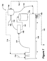
- FIG. 7 shows a schematic representation of yet another embodiment of the inventive process.
- Unit 700 comprises an auger reactor 730.
- Biomass 710 is fed into auger reactor 730 at zone A, together with heat carrier particles 715.
- the auger screw is operated such that the biomass particles and the heat carrier particles travel from zone A in the direction of zone B, in countercurrent with hot gas 741 from regenerator 740.
- the auger reactor is operated such that zone A is kept at or near 300 °C, and zone B is kept at or near 500 °C. Heat is supplied to reactor 730 by hot heat carrier particles 715 and hot gas 741.
- Gaseous and vaporized liquid reaction products are transferred to condensor 750, where the vaporized liquid products are condensed to bio-oil 751, which is sent to storage tank 770.
- Gaseous reaction products 752 from condensor 750 are mixed with air 753, and sent to regenerator 740.
- Solids from auger reactor 730 are collected in separator 780, where the solids are split into a char/ash stream 781 and a coke-laden heat carrier particle stream 782. The latter are regenerated in regenerator 740.
Landscapes
- Chemical & Material Sciences (AREA)
- Oil, Petroleum & Natural Gas (AREA)
- Engineering & Computer Science (AREA)
- Organic Chemistry (AREA)
- Combustion & Propulsion (AREA)
- Materials Engineering (AREA)
- Chemical Kinetics & Catalysis (AREA)
- General Chemical & Material Sciences (AREA)
- Production Of Liquid Hydrocarbon Mixture For Refining Petroleum (AREA)
- Processing Of Solid Wastes (AREA)
Priority Applications (7)
| Application Number | Priority Date | Filing Date | Title |
|---|---|---|---|
| EP08171256A EP2199364A3 (de) | 2008-12-10 | 2008-12-10 | Gegenstromverfahren zur Umwandlung von Biomasse |
| US13/131,825 US20110258912A1 (en) | 2008-12-10 | 2009-12-10 | Counter-current process for biomass conversion |
| CA2744742A CA2744742A1 (en) | 2008-12-10 | 2009-12-10 | Counter-current process for biomass conversion |
| BRPI0922854A BRPI0922854A2 (pt) | 2008-12-10 | 2009-12-10 | processo contracorrente para conversão de biomassa |
| PCT/US2009/067572 WO2010068809A1 (en) | 2008-12-10 | 2009-12-10 | Counter-current process for biomass conversion |
| EP09832571A EP2376596A1 (de) | 2008-12-10 | 2009-12-10 | Gegenstromverfahren zur umwandlung von biomasse |
| CN2009801500280A CN102245739A (zh) | 2008-12-10 | 2009-12-10 | 生物质转化的逆流过程 |
Applications Claiming Priority (1)
| Application Number | Priority Date | Filing Date | Title |
|---|---|---|---|
| EP08171256A EP2199364A3 (de) | 2008-12-10 | 2008-12-10 | Gegenstromverfahren zur Umwandlung von Biomasse |
Publications (2)
| Publication Number | Publication Date |
|---|---|
| EP2199364A2 true EP2199364A2 (de) | 2010-06-23 |
| EP2199364A3 EP2199364A3 (de) | 2010-10-06 |
Family
ID=42101872
Family Applications (2)
| Application Number | Title | Priority Date | Filing Date |
|---|---|---|---|
| EP08171256A Withdrawn EP2199364A3 (de) | 2008-12-10 | 2008-12-10 | Gegenstromverfahren zur Umwandlung von Biomasse |
| EP09832571A Withdrawn EP2376596A1 (de) | 2008-12-10 | 2009-12-10 | Gegenstromverfahren zur umwandlung von biomasse |
Family Applications After (1)
| Application Number | Title | Priority Date | Filing Date |
|---|---|---|---|
| EP09832571A Withdrawn EP2376596A1 (de) | 2008-12-10 | 2009-12-10 | Gegenstromverfahren zur umwandlung von biomasse |
Country Status (6)
| Country | Link |
|---|---|
| US (1) | US20110258912A1 (de) |
| EP (2) | EP2199364A3 (de) |
| CN (1) | CN102245739A (de) |
| BR (1) | BRPI0922854A2 (de) |
| CA (1) | CA2744742A1 (de) |
| WO (1) | WO2010068809A1 (de) |
Cited By (2)
| Publication number | Priority date | Publication date | Assignee | Title |
|---|---|---|---|---|
| CN102949957A (zh) * | 2011-08-26 | 2013-03-06 | 北京低碳清洁能源研究所 | 用于热解碳质材料的催化热载体及其制备方法 |
| EP2800799A4 (de) * | 2012-01-06 | 2015-08-26 | Kior Inc | Zweistufiger reaktor und verfahren zur umwandlung eines festen biomassematerials |
Families Citing this family (41)
| Publication number | Priority date | Publication date | Assignee | Title |
|---|---|---|---|---|
| US9382489B2 (en) | 2010-10-29 | 2016-07-05 | Inaeris Technologies, Llc | Renewable heating fuel oil |
| US8377152B2 (en) * | 2010-10-29 | 2013-02-19 | Kior, Inc. | Production of renewable bio-distillate |
| US9447350B2 (en) | 2010-10-29 | 2016-09-20 | Inaeris Technologies, Llc | Production of renewable bio-distillate |
| US8669405B2 (en) | 2011-02-11 | 2014-03-11 | Kior, Inc. | Stable bio-oil |
| US9315739B2 (en) | 2011-08-18 | 2016-04-19 | Kior, Llc | Process for upgrading biomass derived products |
| US8367881B2 (en) | 2011-05-09 | 2013-02-05 | Cool Planet Biofuels, Inc. | Method for biomass fractioning by enhancing biomass thermal conductivity |
| US10252951B2 (en) | 2011-06-06 | 2019-04-09 | Cool Planet Energy Systems, Inc. | Biochars and biochar treatment processes |
| US12054440B2 (en) | 2011-06-06 | 2024-08-06 | Carbon Technology Holdings, LLC | Method for application of biochar in turf grass and landscaping environments |
| US10640429B2 (en) | 2011-06-06 | 2020-05-05 | Cool Planet Energy System, Inc. | Methods for application of biochar |
| US10550044B2 (en) | 2011-06-06 | 2020-02-04 | Cool Planet Energy Systems, Inc. | Biochar coated seeds |
| US8568493B2 (en) | 2011-07-25 | 2013-10-29 | Cool Planet Energy Systems, Inc. | Method for producing negative carbon fuel |
| US10059634B2 (en) | 2011-06-06 | 2018-08-28 | Cool Planet Energy Systems, Inc. | Biochar suspended solution |
| US10118870B2 (en) | 2011-06-06 | 2018-11-06 | Cool Planet Energy Systems, Inc. | Additive infused biochar |
| US10392313B2 (en) | 2011-06-06 | 2019-08-27 | Cool Planet Energy Systems, Inc. | Method for application of biochar in turf grass and landscaping environments |
| US10173937B2 (en) | 2011-06-06 | 2019-01-08 | Cool Planet Energy Systems, Inc. | Biochar as a microbial carrier |
| US9216916B2 (en) | 2013-10-25 | 2015-12-22 | Cool Planet Energy Systems, Inc. | System and method for purifying process water produced from biomass conversion to fuels |
| US10233129B2 (en) | 2011-06-06 | 2019-03-19 | Cool Planet Energy Systems, Inc. | Methods for application of biochar |
| US11279662B2 (en) | 2011-06-06 | 2022-03-22 | Carbon Technology Holdings, LLC | Method for application of biochar in turf grass and landscaping environments |
| US9809502B2 (en) | 2011-06-06 | 2017-11-07 | Cool Planet Energy Systems, Inc. | Enhanced Biochar |
| US9980912B2 (en) | 2014-10-01 | 2018-05-29 | Cool Planet Energy Systems, Inc. | Biochars for use with animals |
| US8317891B1 (en) | 2011-06-06 | 2012-11-27 | Cool Planet Biofuels, Inc. | Method for enhancing soil growth using bio-char |
| US10696603B2 (en) | 2011-06-06 | 2020-06-30 | Carbon Technology Holdings, LLC | Mineral solubilizing microorganism infused biochars |
| US9493379B2 (en) * | 2011-07-25 | 2016-11-15 | Cool Planet Energy Systems, Inc. | Method for the bioactivation of biochar for use as a soil amendment |
| US10322389B2 (en) | 2014-10-01 | 2019-06-18 | Cool Planet Energy Systems, Inc. | Biochar aggregate particles |
| US12421176B2 (en) | 2011-06-06 | 2025-09-23 | Carbon Technology Holdings, LLC | Biochar as a microbial carrier |
| US12084392B2 (en) | 2011-06-06 | 2024-09-10 | Carbon Technology Holdings, LLC | Treated biochar for use in water treatment systems |
| US11214528B2 (en) | 2011-06-06 | 2022-01-04 | Carbon Technology Holdings, LLC | Treated biochar for use in water treatment systems |
| US10427069B2 (en) | 2011-08-18 | 2019-10-01 | Inaeris Technologies, Llc | Process for upgrading biomass derived products using liquid-liquid extraction |
| US20130327627A1 (en) * | 2012-06-12 | 2013-12-12 | Phillips 66 Company | Catalytic biomass pyrolysis in an auger reactor |
| US20130327626A1 (en) * | 2012-06-12 | 2013-12-12 | Phillips 66 Company | Catalytic pyrolysis of biomass in an auger reactor |
| US11426350B1 (en) | 2014-10-01 | 2022-08-30 | Carbon Technology Holdings, LLC | Reducing the environmental impact of farming using biochar |
| US10472297B2 (en) | 2014-10-01 | 2019-11-12 | Cool Planet Energy System, Inc. | Biochars for use in composting |
| US11053171B2 (en) | 2014-10-01 | 2021-07-06 | Carbon Technology Holdings, LLC | Biochars for use with animals |
| US12599151B2 (en) | 2014-10-01 | 2026-04-14 | Talipot Cool Extract (Ip), Llc | Biochars, biochar extracts and biochar extracts having soluble signaling compounds and method for capturing material extracted from biochar |
| US11097241B2 (en) | 2014-10-01 | 2021-08-24 | Talipot Cool Extract (Ip), Llc | Biochars, biochar extracts and biochar extracts having soluble signaling compounds and method for capturing material extracted from biochar |
| AU2015328022B2 (en) | 2014-10-01 | 2020-01-23 | Carbon Technology Holdings, LLC | Biochars and biochar treatment processes |
| US10870608B1 (en) | 2014-10-01 | 2020-12-22 | Carbon Technology Holdings, LLC | Biochar encased in a biodegradable material |
| US10563129B2 (en) | 2015-09-25 | 2020-02-18 | Inaeris Technologies, Llc | Use of cooling media in biomass conversion process |
| US10619103B2 (en) | 2015-09-25 | 2020-04-14 | Inaeris Technologies, Llc | Catalyst addition to a circulating fluidized bed reactor |
| US11866329B2 (en) | 2017-12-15 | 2024-01-09 | Talipot Cool Extract (Ip), Llc | Biochars, biochar extracts and biochar extracts having soluble signaling compounds and method for capturing material extracted from biochar |
| RU2732411C1 (ru) * | 2019-09-11 | 2020-09-16 | Федеральное государственное бюджетное учреждение науки Объединенный институт высоких температур Российской академии наук (ОИВТ РАН) | Способ пиролиза гранулированной биомассы в автотермальном режиме |
Family Cites Families (13)
| Publication number | Priority date | Publication date | Assignee | Title |
|---|---|---|---|---|
| US2694037A (en) * | 1950-04-07 | 1954-11-09 | Shell Dev | Method and apparatus for the production of shale oil from oil shale |
| CA1081466A (en) * | 1976-03-26 | 1980-07-15 | David S. Mitchell | Countercurrent plug-like flow of two solids |
| GB2028366B (en) * | 1978-08-21 | 1982-11-24 | G N I Energeti I Im Gk Krzhizh | Heat processing of pulverized carboniferous material |
| US5019135A (en) * | 1987-10-13 | 1991-05-28 | Battelle Memorial Institute | Method for the catalytic conversion of lignocellulosic materials |
| US5792340A (en) * | 1990-01-31 | 1998-08-11 | Ensyn Technologies, Inc. | Method and apparatus for a circulating bed transport fast pyrolysis reactor system |
| DE4190445T (de) * | 1990-03-13 | 1992-08-27 | ||
| ATE257170T1 (de) * | 1999-11-11 | 2004-01-15 | Tno | Flash-pyrolyse in einem zyklon |
| US20050095183A1 (en) * | 2003-11-05 | 2005-05-05 | Biomass Energy Solutions, Inc. | Process and apparatus for biomass gasification |
| US7374742B2 (en) * | 2003-12-19 | 2008-05-20 | Bechtel Group, Inc. | Direct sulfur recovery system |
| FR2885909B1 (fr) * | 2005-05-23 | 2008-01-18 | Thermya Sa | Procede de distillation de produits solides organiques et notamment pour le recyclage des bois traites |
| US20080006520A1 (en) * | 2006-07-06 | 2008-01-10 | Badger Phillip C | Method and system for accomplishing flash or fast pyrolysis with carbonaceous materials |
| US20100209965A1 (en) * | 2006-07-17 | 2010-08-19 | Bioecon International Holding N.V. | Catalytic pyrolysis of fine particulate biomass, and method for reducing the particle size of solid biomass particles |
| WO2009126765A2 (en) * | 2008-04-09 | 2009-10-15 | Velocys Inc. | Process for converting a carbonaceous material to methane, methanol and/or dimethyl ether using microchannel process technology |
-
2008
- 2008-12-10 EP EP08171256A patent/EP2199364A3/de not_active Withdrawn
-
2009
- 2009-12-10 CN CN2009801500280A patent/CN102245739A/zh active Pending
- 2009-12-10 WO PCT/US2009/067572 patent/WO2010068809A1/en not_active Ceased
- 2009-12-10 CA CA2744742A patent/CA2744742A1/en not_active Abandoned
- 2009-12-10 EP EP09832571A patent/EP2376596A1/de not_active Withdrawn
- 2009-12-10 BR BRPI0922854A patent/BRPI0922854A2/pt not_active IP Right Cessation
- 2009-12-10 US US13/131,825 patent/US20110258912A1/en not_active Abandoned
Cited By (3)
| Publication number | Priority date | Publication date | Assignee | Title |
|---|---|---|---|---|
| CN102949957A (zh) * | 2011-08-26 | 2013-03-06 | 北京低碳清洁能源研究所 | 用于热解碳质材料的催化热载体及其制备方法 |
| EP2800799A4 (de) * | 2012-01-06 | 2015-08-26 | Kior Inc | Zweistufiger reaktor und verfahren zur umwandlung eines festen biomassematerials |
| US10934491B2 (en) | 2012-01-06 | 2021-03-02 | Mard, Inc. | Two-stage process for conversion of solid biomass material |
Also Published As
| Publication number | Publication date |
|---|---|
| EP2376596A4 (de) | 2011-10-19 |
| CA2744742A1 (en) | 2010-06-17 |
| WO2010068809A1 (en) | 2010-06-17 |
| BRPI0922854A2 (pt) | 2016-04-26 |
| US20110258912A1 (en) | 2011-10-27 |
| EP2199364A3 (de) | 2010-10-06 |
| CN102245739A (zh) | 2011-11-16 |
| EP2376596A1 (de) | 2011-10-19 |
Similar Documents
| Publication | Publication Date | Title |
|---|---|---|
| EP2199364A2 (de) | Gegenstromverfahren zur Umwandlung von Biomasse | |
| EP2403926B1 (de) | Verfahren zur thermochemischen umwandlung von biomasse | |
| US8114176B2 (en) | Catalytic steam gasification of petroleum coke to methane | |
| DK2633003T3 (en) | PREPARATION OF SYNTHESE GAS BY HEATING OXIDATED BIOMASS WITH A HOT GAS OBTAINED FROM OXIDATION OF RESIDUAL PRODUCTS | |
| CA2804315C (en) | Multi-stage biomass conversion | |
| JP2020073688A (ja) | 都市固形廃棄物(msw)原料に由来する高生物起源濃度のフィッシャー−トロプシュ液体の製造プロセス | |
| EP3083008B1 (de) | Verfahren und vorrichtung zur reinigung von rohstoffgas | |
| EA005709B1 (ru) | Способ переработки углеродосодержащего материала | |
| KR20080067676A (ko) | 타르를 제자리에서 제거함을 수반하는, 가스화 방법 및시스템 | |
| WO2011103047A2 (en) | Low oxygen biomass-derived pyrolysis oils and methods for producing the same | |
| WO2015010448A1 (zh) | 一种由固体有机物水蒸气气化制取富氢气体的方法 | |
| CN101896580A (zh) | 用于生产合成气和醇的方法和装置 | |
| US12270002B2 (en) | Process of treating carbonaceous material and apparatus therefor | |
| US20140318944A1 (en) | Catalytic pyrolysis of biomass using a multi-stage catalyst regenerator | |
| KR100636616B1 (ko) | 음식물 쓰레기의 급속 열분해 장치 및 그 방법 | |
| TWI397580B (zh) | 具有原位焦油移除作用的氣化方法及系統 | |
| Aktaş et al. | Temperature and Positioning Effects of Spent Fluid Catalytic Cracking Catalyst in the Reactor on Pyrolysis of Polyethylene Terephthalate | |
| MX2008004832A (en) | Catalytic steam gasification of petroleum coke to methane |
Legal Events
| Date | Code | Title | Description |
|---|---|---|---|
| PUAI | Public reference made under article 153(3) epc to a published international application that has entered the european phase |
Free format text: ORIGINAL CODE: 0009012 |
|
| AK | Designated contracting states |
Kind code of ref document: A2 Designated state(s): AT BE BG CH CY CZ DE DK EE ES FI FR GB GR HR HU IE IS IT LI LT LU LV MC MT NL NO PL PT RO SE SI SK TR |
|
| AX | Request for extension of the european patent |
Extension state: AL BA MK RS |
|
| PUAL | Search report despatched |
Free format text: ORIGINAL CODE: 0009013 |
|
| AK | Designated contracting states |
Kind code of ref document: A3 Designated state(s): AT BE BG CH CY CZ DE DK EE ES FI FR GB GR HR HU IE IS IT LI LT LU LV MC MT NL NO PL PT RO SE SI SK TR |
|
| AX | Request for extension of the european patent |
Extension state: AL BA MK RS |
|
| AKY | No designation fees paid | ||
| REG | Reference to a national code |
Ref country code: DE Ref legal event code: R108 Effective date: 20110526 |
|
| STAA | Information on the status of an ep patent application or granted ep patent |
Free format text: STATUS: THE APPLICATION IS DEEMED TO BE WITHDRAWN |
|
| 18D | Application deemed to be withdrawn |
Effective date: 20110407 |